EP0533983B1 - Seifenversorgungsanlage - Google Patents
Seifenversorgungsanlage Download PDFInfo
- Publication number
- EP0533983B1 EP0533983B1 EP91116483A EP91116483A EP0533983B1 EP 0533983 B1 EP0533983 B1 EP 0533983B1 EP 91116483 A EP91116483 A EP 91116483A EP 91116483 A EP91116483 A EP 91116483A EP 0533983 B1 EP0533983 B1 EP 0533983B1
- Authority
- EP
- European Patent Office
- Prior art keywords
- liquid soap
- tank
- supplying device
- air
- feeding pipe
- Prior art date
- Legal status (The legal status is an assumption and is not a legal conclusion. Google has not performed a legal analysis and makes no representation as to the accuracy of the status listed.)
- Expired - Lifetime
Links
Images








Classifications
-
- A—HUMAN NECESSITIES
- A47—FURNITURE; DOMESTIC ARTICLES OR APPLIANCES; COFFEE MILLS; SPICE MILLS; SUCTION CLEANERS IN GENERAL
- A47K—SANITARY EQUIPMENT; ACCESSORIES THEREFOR, e.g. TOILET ACCESSORIES
- A47K5/00—Holders or dispensers for soap, toothpaste or the like
- A47K5/14—Foam or lather making devices
Definitions
- This invention relates to a liquid soap supplying device for use in bashing hands, hair and body and for other desired applications.
- a liquid soap supplying device comprised of a tank for storing liquid soap, a pressurizing device for pressurizing an interior side of the tank and a discharging nozzle communicating with the tank through a liquid soap feeding pipe (for example, see Jap.U.M.Laid-Open No.Hei 2-92789).
- This supplying device feeds liquid soap in a tank by a pressurizing force of a pressurizing device to a discharging nozzle and discharges the liquid soap of steam-like flow from the discharging port under an opening or closing operation of the discharging nozzle.
- a cleaning system for dispensing an aerated cleaning liquid includes a container for the cleaning liquid, means for pressurizing the cleaning liquid in use, a liquid supply line for conveying pressurized cleaning liquid from the container, a pressurized air line for receiving air under pressure, a mixing means for receiving pressurized air from the air line and also for receiving liquid under pressure from the liquid supply line and being arranged to cause mixing of the pressurized air and the cleaning liquid, a discharge outlet downstream of the mixing means and where cleaning liquid is discharged in aerated form when in use, and a selectively operable control valve located at or in close proximity to the discharge outlet to be operable by a user to activate the known system.
- a foam dispensing device air return system having a foam producing unit mounted in the discharge port is known from US-A-45 31 659.
- the present invention is based on solving the problems as described above and, in particular, to provide a supplying device for use in discharging bubbled liquid soap without forming any splashing and dropping off, where the liquid soap strikes against the hands, to prevent liquid soap remaining in the piping communicating with a tank and in the discharging nozzle from being fixed in the supplying device and clogging the piping and to provide a supplying device which is cheap and simple in structure and still permits the supply of soap to a plurality of supply systems.
- a further object advantageously solved by the present invention is to enable a fine texture of the liquid soap or the like to be optionally adjusted in the supplying device of the aforesaid first object in compliance with a preference of a user.
- a third object advantageously solved by the present invention is to improve a safety characteristic of the supplying device of the aforesaid first object.
- a fourth object advantageously solved by the present invention is to enable an efficient use of liquid soap to be attained when the supplying device of the aforesaid first object is operated or used.
- a fifth object advantageously solved by the present invention is to provide a liquid soap supplying device in an apparatus having a plurality of supplying portions for use in discharging bubbled liquid soap in which a remained amount of liquid soap in each of the tanks at each of the supplying portions can be totally displayed.
- the aforesaid further object can be accomplished according to dependent claim 6 by arranging a flow rate adjusting valve for use in adjusting a supplying amount of air to the discharging nozzle at a proper location in the air feeding pipe.
- the aforesaid third object can be accomplished according to dependent claim 18 by means of arranging an emergency stop control means for stopping an operation of the pressurizing device by sensing an abnormal state of a system in the control part.
- the fourth object of the present invention can be accomplished according to dependent claims 10 to 13 by means of a remained amount sensor for sue in performing a step-wise sensing of a remained amount of liquid soap in the tank and a remained amount displaying part for use in displaying in a step-wise manner a remained amount of liquid soap in the tank in response to a sensing signal from the remained amount sensor of the like.
- the fifth object of the present invention can be accomplished according to dependent claim 25 by a constitution of the liquid soap supplying device in which a plurality of liquid soap supplying portions comprised of the aforesaid tank, pressurizing device, controlling part, liquid soap feeding pipe, air feeding pipe, discharging nozzle and remained amount sensor or the like are arranged and also a displaying function part for concentrically displaying a remained amount of liquid soap within each of the tanks at each of the aforesaid liquid soap supplying device is provided.
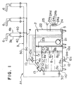
- Fig.1 is a schematic view for showing one preferred embodiment of the liquid soap supplying device of the present invention.
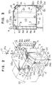
- Fig.2 is a perspective view for showing a tank and a casing.
- Fig.3 is a longitudinal side elevation in section for showing a tank.
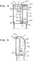
- Fig.4 is a longitudinal front electional view in section for showing a tank.
- Fig.5 is a longitudinal side elevational view in section for showing a casing.
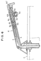
- Fig.6 is an enlarged sectional view for showing a discharging nozzle.
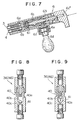
- Fig.7 is an expanded view for showing a substantial part of Fig.6 to indicate a liquid soap discharging state.
- Fig.8 is an enlarged sectional view for showing a check valve.
- Fig.9 is a view for showing an operating state in Fig.8.
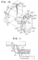
- Fig.10 is an exploded perspective view for showing a tank and a casing.
- Fig.11 is an enlarged sectional view for showing a drain port.
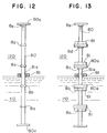
- Fig.12 is a front elevational view partly broken away to show a remained amount sensor.
- Fig.13 is a front elevational view partly broken away to show another example of a remained amount sensor.
- Fig.14 is a flow chart for a controlling operation of the device shown in Fig.1.
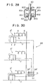
- Figs.15, 20, 29, and 30 are schematic views for showing other liquid soap supplying devices of the present invention, respectively.
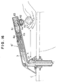
- Fig.16 is an enlarged sectional view for showing a discharging nozzle in Fig.15.
- Fig.17 is a front elevational view partly broken away for showing another example of a discharging nozzle.
- Fig.18 is an enlarged view for showing a substantial part of a mixing chamber in a discharging nozzle in Fig.17.
- Fig.19 is an enlarged sectional view for showing another example of a mixing chamber.
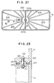
- Fig.21 is a sectional view taken along a line (21)-(21) of Fig. 20.
- Fig.22 is a top plan view for showing a lower part of a main body of a tank.
- Fig.23 is a sectional view taken along a line (23)-(23) of Fig.22.
- Fig.24 is an enalrged view for showing a supplementary port in Fig,20 to indicated a state of an opened supplementary port.
- Fig.25 is a sectional view for showing another example of a supplementary port.
- Fig.26 is a top plan view for showing a supplementary port lid in FIg.25.
- Fig.27 is an enlarged sectional view for showing a discharging nozzle in Fig.20.
- Fig.28 is an enlarged sectinoal view for showing a substantial part of a remained amount sensor in Fig.20.
- Fig.31 is an enlarged view for showing a substantial part in Fig.30.
- Fig.1 shows a liquid soap supplying device A1 comprised of a tank 1, a pressurizing device 2, a liquid soap feeding pipe 3, an air feeding pipe 4, a control part 5 and discharging nozzles 6 or the like and a basic configuration of the device A1 will be described at first.
- the tank 1 has an entire shape of a cylindrical shape, a rectangular cylinder or a spherical shape or any other optional shape and its shape is not restricted at all.
- the tank is comprised of a box-like pressure-proof container as shown in Figs.2 to 5, wherein a liquid soap supplementary port 11 is opened at a middle and higher location in a side wall.
- the container may accumulate liquid soap 110 with the supplementary port 11 being applied as an upper limit location and at the same time an air accumulating part 120 can be kept above the liquid soap 110 and a desired amount of compressed air can be stored there.
- the supplementary port 11 is closed by a lid 13 in such a way as it may be opened or closed.
- a liquid soap discharging port 3a is opened at a bottom part of the tank 1 and a base end of the liquid soap feeding pipe 3 is connected to the discharging port 3a.
- An upper part of the tank 1 is provided with an opened air discharging port 4a which is communicated with the sir accumulation part 120, and a base end of the air feeding pipe 4 is connected to the discharging port 4a.
- a pressure sensor 7 electrically connected to the control part 5 is arranged within the air accumulating part 120, and a compressor 21 for the pressurizing device 2 is communicated through an air intake pipe 23.
- the pressure sensor 7 is comprised of a well-known pressure switch using either a strain gauge or a magnetic resistance element and transmits a pressure within the tank as an electrical signal to the control part 5 by utilizing a variation of an electrical resistance accompanied by a variation of pressure in the tank 1.
- the pressurizing device 2 is constructed such that the compressor 21 and the control part 5 are arranged in the casing 22 separately arranged from the tank 1 and it may easily be fixed to several kinds of tanks.
- the compressor 21 is electrically connected to the control part 5 and an operation of the compressor 21 is controlled by it.
- the control part 5 is comprised of electrical circuits such as ICs or capacitors or the like and is provided with a pressurizing control means for operating the compressor 21 in response to a sensed signal from the pressure sensor 7 when a pressure in the tank 1 becomes less than a low side set pressure P 1 (0.3 kgf/cm 2 in the preferred embodiment) and stopping the compressor 21 when the pressure in the tank 1 becomes more than a higher side set pressure P 2 (0.5 kgf/cm 2 in the preferred embodiment).
- This control part 5 is provided with various control means to be described later.
- the difference between P 1 and P 2 should be set to such a value (value having no trouble) as one endurable against a concurrent use of a continuous use in response to the number of cooperating discharging nozzles 6.
- the higher set pressure should be set to such a value as one allowed in the tank 1 (a value applying a slight surplus to the tank).
- the liquid soap feeding pipe 3 and the air feeding pipe 4 connected to the tank 1 are divided into several segment pipes in the midway parts and then the discharging nozzle 6 is connected to each of the branched pipes.
- the discharging nozzle 6 is mounted at a hand washing basin, a face washing basin, a hair washing basin in their circumferential portions or other desired mounting surfaces C, and has, as shown in Figs.6 and 7, a liquid soap feeding port 6a and an air feeding port 6b in it.
- the liquid soap feeding pipe 3 is connected to the former and the air feeding pipe 4 is connected to the latter.
- An inside part of the discharging nozzle is provided with a mixing chamber 61 communicating with the feeding ports 6a and 6b and an agitating chamber 62 communicating withs the discharging port 6d.
- the mixing chamber 61 and the agitating chamber 62 are communicated to each other through a passage 63 having a small diameter.
- the discharging nozzle 6 is provided with an opening or closing valve 6c, and the agitating chamber 62 has several straighners 6e (3 pieces in the preferred embodiments) mounted therein.
- the opening or closing valve 6c amy be of an electrical or an electromagnetical unit opened for a specified period of time with an electrical signal based on a sensing of hand through a human sensor such as a photo-electrical sensor or the like or a pressing operation of a touch switch or amy be of a manual unit opened while a push button is being depressed under a mechanical operation of pushing the push button or for a specified period of time.
- a human sensor such as a photo-electrical sensor or the like or a pressing operation of a touch switch
- amy be of a manual unit opened while a push button is being depressed under a mechanical operation of pushing the push button or for a specified period of time.
- the manual opening or closing valve 6c operated under an operation of the push button 6c'.
- the liquid soap supplying device A1 constructed as above is operated such that an operation of the compressor 21 is controlled by the control part 5 in such a way as a pressure within the tank 1 is kept at a specified range (0.3 kgf/cm 2 to 0.5 kgf/cm 2 ) and both liquid soap and air are supplied to each of the discharging nozzles 6.
- the push button 6c' is depressed by each of the discharging nozzles 6, the supplied liquid soap and the air are mixed to each other within the mixing chamber 61 and they are agitated by straighners 6e. Then, the liquid soap is discharged in its bubble form.
- a discharging of bubble liquid soap may prevent not only some disadvantages that an excessive strong discharging state of liquid soap under a pressurizing force of the compressor 21 causes the liquid soap to be struck against the hand and splashed or flowed down the hand but also enable an efficient usage of a small amount of liquid soap as well as a saving of the liquid soap.
- the aforesaid device A1 is operated such that the air in the tank 1 is always pressurized or compressed by the pressurizing device 2 to a predetermined pressure to cause both the liquid soap 110 and the air in the tank 1 to be forcedly fed to the discharging nozzle 6 under a pressure of the air, so that even of a plurality of supplying systems, i.e. nozzle systems are arranged, it is not necessary to provide each of the compressor or supplying pumps for each of the systems, liquid soap and air.
- the device is simple in its structure, resulting in that a concentrated supplying system for supplying bubble liquid soap from one supplying source to a plurality of basins and hand washing units can be attained under a low cost.
- liquid soap supplying device A1 comprised of the aforesaid basic configuration
- the nearest location of the aforesaid liquid soap feeding pipe 3 for the tank 1 (the most upstream side of the liquid soap feeding pipe 3) is provided with a check valve 30, and with this check valve, even if the remained liquid soap in the tank 1 is eliminated, the liquid soap is fully filled in the liquid soap feeding pipe 3.
- the air in the tank 1 does not enter the liquid soap feeding pipe 3 and does not cause the remained liquid soap in the feeding pipe 3 to be solidified, resulting in that it does not produce any disadvantages that the liquid soap feeding pipe 3 is clogged.
- the locations near each of the discharging nozzles 6 (the most downstream of the liquid soap feeding pipe 3 and the air feeding pipe 4) branched from the liquid soap feeding pipe 3 and the air feeding pipe 4 may be-provided with check valves 40.
- Such an arrangement as above can prevent some disadvantages that air enters from the discharging nozzles 6 into the liquid soap feeding pipe 3 or liquid soap enters the air feeding pipe 4 to cause the liquid soap to be fixed in each of the pipes 3 and 4 and clog the same.
- the present invention prevents the liquid soap in the liquid soap feeding pipe 3 from being pushed back by air can can provide a stable characteristic in discharging operation at the beginning of discharging liquid soap.
- both check valves 30 and 40 are shown to be installed and any one of them will be placed in a practical system.
- the aforesaid check valves 40 are arranged in rising parts 3b and 4b in the liquid soap feeding pipe 3 and the air feeding pipe 4, respectively, and as shown in Figs.5 and 6, their details are made such that there are provided a spherical valve member 40b within a valve chamber 40a arranged in a coupling pipe 41 and a funnel-like valve seat 40c on which the valve member 40b is seated, and the valve is closed by its own weight of the valve member 40b, resulting in that, as compared with a system in which the valve is closed by a forced biasing means such as a spring or the like, even if the inside part of the bank 1 shows a low pressure, a pushing-up of the valve member 40b is not prohibited and a reliability of the check valve 40 can be improved.
- a forced biasing means such as a spring or the like
- the air feeding pipe 4 is provided with either a manual or an electrical flow rate adjusting valve 50 at its appropriate midway location, this adjusting valve 50 is manually or electrically operated so as to adjust an air supplying amount for the discharging nozzles 6, thereby a fine texture or hardness of bubble discharged liquid soap can be optionally adjusted in compliance with a preference of user.
- a complete closing of the air feeding pipe 4 stops an air supplying to the discharging nozzles 6 to enable the non-bubbled water-flow like liquid soap to be discharged from the discharging nozzles 6.
- the casing 22 is formed to be fixed to any one of the right and left side surfaces of the tank 1 in such a way as it may be conveniently placed in response to a setting position of the tank 1.
- the right and left side surfaces of the tank 1 are provided with a plurality of threaded holes 14 at several positions and further the right and left side surfaces of the casing 22 are provided with a plurality of holes 22a and 22b in such a way as they may oppositely face against each of the threaded holes 14.
- extreme ends of long bolts 22c inserted from holes 22a at one side surface are threadably fitted to the threaded holes 14 through holes 22b at the other side surface and the casing 22 is removably fixed to the side surface of the casing 22.
- a bottom wall of the tank 1 is provided with a drain port 12 for use in discharging deposits.
- the drain port 12 has a concave portion 12a having a proper size, a bottom part of the concave portion 12a is provided with a discharging port 12b, a drain pipe 12c is drawn from the discharging port 12b and the drain pipe 12c is provided with an opening or closing valve 12d.
- the deposit in the tank 1 is accumulated in the concave part 12a and then the deposit is passed through a drain pipe 12c and discharged out of the tank 1 by opening the opening or closing valve 12d.
- a drain pipe 12c and discharged out of the tank 1 by opening the opening or closing valve 12d.
- a remained volume sensor 8 for the liquid soap 110 is arranged in the rank 1, an opening or closing sensor 9 is arranged in the supplementary port 11 and also an air drain port 10 having a safety valve 10a is arranged in the midway part of the air feeding pipe 4.
- a front surface of the casing 22 is provided with a remained volume displaying part 24 and a buzzer 25.
- Each of the remained volume sensor 8, opening or closing sensor 9, safety valve 10a, remained volume displaying part 24 and buzzer 25 is electrically connected to the control part 5 and all the operations of these devices are controlled by the control part 5.
- the remained volume sensor 8 is, as shown in Fig.12, made such that an annular float magnet 81 is inserted onto a guide shaft 80 uprighted within the tank 1 in such a way as the magnet 81 may be moved up and down freely.
- An outer periphery of the guide shaft 80 is provided with contact pints (magnetic sensing elements) 8a to 8e in five steps and the remained volume sensor 8 is constructed by a multi-staged float switch provided with a contact element 81a contacted to or moved away from each of the contact points 8a to 8e at an inner periphery of the float magnet 81.
- the remained volume of liquid soap is detected in a step-wise manner through a contact between the contact element 81a of the float magnet 81 and each of the contact points 8a to 8e of the guide shaft 80, the detected volume is transmitted as an electrical signal to the control part 5 and then the remained volume of liquid soap within the tank 1 is acknowledged in a stepwise manner.
- the lower-most stage contact point 8a in the remained volume sensor 8 is placed at a location higher than a liquid soap discharging port 3a in the tank 1 and the uppermost state contact point 8e is arranged at a location lower than the supplementary port 11.
- Reference numerals 80a in the figure denote stoppers arranged at an upper end and a lower end of the guide shaft 80.
- the aforesaid remained volume sensor 8 has contact points 8a to 8e in multi-stage manner at an outer periphery of the guide shaft 80 and it is also possible to arranged the upper and lower stoppers 80a for every contact points 8a to 8e and to construct to have the float magnets 81.
- the opening or closing sensor 9 is comprised of a microswitch arranged in the supplementary port 11.
- the opening or closing sensor 9 may transmit each of a closed state and an opened state of the supplementary port 11 with a lid 13 as an electrical signal to the control part 5 so as to cause the control part 5 to acknowledge an opened or closed (opened or closed state of the lid 13) state of the supplementary port 11.
- a safety valve 10a of the air drain port 10 is comprised of an electrical (electromagnetical) three-way valve to open the air feeding pipe 4 under a normal state and to close the air drain port 10.
- the safety valve 100 is controlled by the control part 5 in such a way as it may be operated when the opening or closing sensor 9 detects an opening of the supplementary port 11 (a lid 13 is opened), or when the remained volume sensor 8 detects the lower-most position (8a) of the liquid soap remained volume, or when the pressure sensor 7 detects a value more than a high set value P 3 (0.7 kgf/cm 2 in the preferred embodiment), opens the air drain port 10, removes the compressed air in the tank 1 and at the same time operas again after a specified period of time (for example, 60 seconds) elapses and closes the air drain port 10.
- the air drain port 10 can be arranged at the tank 1 separately and independently from the air feeding pipe 4 and in this case the safety valve 10a is constructed by an electrical (electro-magnetical) opening or
- the safety valve 10a is controlled by the control part 5 in order to prevent a poor opening or closing caused by a fxing in such a way as it may be opened or closed only for a slight period of time (for example, 0.1 second) every time the compressor 21 is started to operate.
- the remained volume displaying part 24 is constructed such that light emitting diode elements 24a to 24e are arranged in a multi-stage manner in correspondence with each of the contact points 8a to 8e in the remained volume sensor 8 and at the same time each of the elements 24a to 24e is electrically connected.
- the device is controlled by the control part 5 in such a way as each of the elements 24a to 24e is lit through a sensing of the remained volume with the corresponding contact points 8a to 8e, it is lit for a specified period of time (for example, 5 seconds) with a sensing singal from the upper-most contact point 8e at the upper-most stage element 24e, an overflow during supplementing of the liquid soap is alarmed and after this operation it is lit.
- the buzzer 25 is controlled by the control part 5 in such a way as it may ring for a specified period of time (for example, 5 seconds) when the remained volume sensor 8 detects the upper-most level (8e) of the remained volume of liquid soap and an over-flow at the time 01 supplementing the liquid soap is alarmed.
- control part 5 is provided with (I) a control means for acknowledging a remained amount of the liquid soap 110 in the tank 1 in s stepwise manner and operating the remained volume displaying part 24 as described above, (II) a control means for preventing a flying of the lid 13 and preventing a fixing of the liquid soap feeding pipe 3 so as to operate the safety valve 10a upon acknowledging that the remained volume of the liquid soap 110 in the tank 1 descends down to its lower-most location, (III) a control means for stopping an operation of the compressor 21 upon acknowledgement of an opened state of the lid 13 (an opened state of the supplementing port 11), (IV) a control means for alarming an over-flow state for operating the remained volume displaying part 24 and the buzzer 25 upon acknowledgement of an increasing of the remained volume of the liquid soap 110 in the tank 1 up to the upper-most position, (V) a control means for protecting the tank so as to operate the safety valve 10a upon acknowledgement of a
- the compressor 21 is operated such that a pressure within the tank 1 may be kept within a specified range while the supplementary port 11 being closed and then bubble-like liquid soap can be discharged from each of the discharging nozzles 6.
- a remained volume of the liquid soap 110 in the tank 1 is displayed in the remained volume displaying part 24 in a step-wise manner and a supplementing of the liquid soap can be efficiently carried out.
- the present invention provides an effect to eliminate a probability of pumping-out of the lid 13 due to an inner pressure in the tank 1, to perform a safe supplementation of the liquid soap and to prevent a useless operation of the compressor 21 when the lid 13 is released.
- the arrangement in which the liquid soap taking-out port 3a is arranged at a location lower than the lower-most location (8a) of the remained volume sensor 8 may prevent the remained volume of the liquid soap 110 from being placed lower than the liquid soap discharging port 3a.
- the buzzer 25 is rung, the upper-most element 24e in the remained volume displaying part 24 is illuminated to alarm an over-flow condition of the liquid soap and then a useless consumption of the liquid soap can be prevented.
- the safety valve 10a is operated to reduce a pressure within the tank 1 and to protect that tank 1.
- the safety valve 10a is opened or closed every time the compressor 21 is operated to cause the liquid soap adhered to the safety valve 10a to be solidified and further to prevent a possibility of not operating the safety valve 10a and then a reliability in controlling operation described above or to be described later is improved.
- the safety valve 10a is opened or closed every time the pressurizing pump 21 is operated to cause the liquid soap adhered to the safety valve 10a to be solidified and further to prevent a possibility of not operating the safety valve 10a and then a reliability in controlling operation described above or to be described later is improved.
- control part 5 is provided with an emergency stopping means for stopping an operation of the compressor 21 when an abnormal state indicated in the following 1 or 2 is detected, opening the air drain port 10 for a specified period of time under an operation of the safety valve 10a, illuminating each of all elements 24a to 24e at the remained volume displaying part 24 to inform an occurrence of abnormal state at the device A1, stopping the operation of the compressor 21 when an abnormal state indicated in 3 is detected and opening the air drain port 10 for a specified period of time, diminishing the light emitting diode elements 24a to 24e corresponding to the contact points 8a to 8e showing a detection of the remained volume other than the liquid surface of the remained liquid soap, illuminating other elements 24a to 24e and informing an occurrence of abnormal state.
- an emergency stopping means for stopping an operation of the compressor 21 when an abnormal state indicated in the following 1 or 2 is detected, opening the air drain port 10 for a specified period of time under an operation of the safety valve 10a, illuminating each of all elements 24a to 24e at
- Fig.14 is shown the flow-chart concerning the control over the aforesaid liquid soap supplying device A1.
- a controlling function other than the above described in the above supplying device A1, for example, to arrange a temperature sensor near the compressor 21 in the casing 22 and when the temperature sensor detects a value more than the set temperature (an overloaded condition of the compressor 21), a control means may be provided for stopping the compressor 21 or the like.
- Liquid soap supplying devices A2 to A4 will be described in which each of the composing elements for the supplying device A1 will be described as follows.
- Figs.15 and 16 there is illustrated the liquid soap supplying device A2 having discharging nozzles 6' provided with electro-magnetic or electrical opening or closing valves 65 opened for a specified period of time upon detecting a user in place of the above discharging nozzles 6.
- the discharging nozzles 6' are provided with the liquid soap feeding port 6a, air feeding port 6b, air discharging port 6d, straighners 6e, mixing chamber 61, agitating chamber 62 and a flow passage 63 or the like in the same manner as that of the above discharging nozzles 6 and further it has a photo-electrical sensor 6f at a predetermined location at the base end for sensing a hand extended just below the discharging port 6d.
- the opening or closing valves 65 are arranged at downstream sides of the check valves 40 in the liquid soap feeding pipe 3 and the air feeding pipe 4 and further cooperatively connected to the control part 5 in such a way as the valve may be opened or closed for a predetermined period of time through a sensing of the hand by the sensor 6f.
- the sensor 6f may sense automatically the hand or may be one of a sensor touch type.
- the opening or closing valve 65 is opened for the predetermined period of time, the liquid soap of specified amount and the air are supplied to the discharging nozzles 6' and then only a specified amount of bubbled liquid soap is discharged from the discharging port 6d.
- the opening or closing valve 65 is opened for the predetermined period of time, the liquid soap of specified amount and the air are supplied to the discharging nozzles 6' and then only a specified amount of bubbled liquid soap is discharged from the discharging port 6d.
- control part 5 is provided with a control means for avoiding a judgement of abnormal state in which the pressure within the tank 1 is rapidly decreased when more than a plurality of discharging nozzles 6' are used concurrently.
- the means are, for example, (1) when the two discharging nozzles 6' are used concurrently, the opening or closing valves 65 are controlled so as to be closed at 70% of a normal discharging time, (2) when the other discharging nozzle 6' is used during a use of one discharging nozzle 6', the former discharging nozzle 6' is stopped in about one second and the latter discharging nozzle 6' is discharged after about one second under a control of the opening or closing valve 65, and (3) the opening or closing valve 65 is controlled in such a way as when the other discharging nozzle 6' is used during a continuation of the discharging time of 70% at the previous discharging nozzle 6', the discharging nozzle 6' of previous one is immediately closed to make a rapid stopping of the discharging operation and the discharging of the latter discharging nozzle 6' for 70% discharging time of the normal time.
- a limiting capability of the compressor 21 is set in such a way as when five discharging nozzles 6' are used concurrently no discharging is carried from the two discharging nozzles 6' or as one example, the opening or closing valves 65 of the two discharging nozzles 6' are not opened.
- the opening or closing valves 65 may be controlled in such a way as the opening or closing valves 65 in the air feeding pipe 4 are closed and the liquid soap is changed over to a discharging of water flow and then the air in the tank 1 may not be rapidly decreased.
- Figs.17 to 19 is illustrated an example of modification around the discharging port 6d in the above discharging nozzle 6'.
- the discharging nozzle 6'' is made such that a discharging port 6d is vertically arranged at an extreme end lower surface of the main body having a hollow interior, in which the extreme end of the liquid soap feeding pipe 3 and the air feeding pipe 4 are connected to a primary side of the discharging port 6d and at the same time the two straighners 6e are arranged in sequence in the discharging port 6d from the upstream side, a spacer 66 is arranged between each of the straighners 6e and 6e and then a spacer 66 is arranged at the primary side of the straighner 6e at the upstream side.
- the spacer 66 has a substantial funnel-like mixing chamber 66b by downwardly inclining a central part of the spacer main body 66a, and a communication-passage 66d is formed over a lower surface of the spacer main body 66a from the deepest part 66c of the mixing chamber 66b.
- the spacer 66 amy be further added to the secondary side of the downstream side straighner 6e in the discharging port 6d and the number of straighners and spacers can be properly varied.
- the opening or closing valves 65 are opened for a specified period of time to feed the liquid soap and the air toward the discharging nozzle 6'' and further the liquid soap and the air are forcedly blown from the extreme ends of the liquid soap feeding pipe 3 and the air feeding pipe 4 toward into the mixing chamber 66b.
- the liquid soap and the air are sufficiently and positively mixed within the substantial funnel-like mixing chamber 66b, pass through the communicating passage 66d arranged in the deepest part 66c of the mixing chamber 66b, and they are agitated by the straighner 6e, agitated by the downstream-side spacer 66 and the straighner 6e and then the liquid soap and the air are discharged from the extreme end of the discharging port 6d under a fine bubbled state.
- a funnel-like mixing chamber 66b is arranged at the up-stream side of each of the straighners 6e arranged in the discharging port 6d, the liquid soap and the air are sufficiently and positively mixed within the mixing chamber 66b, thereafter they are agitated by the straighner 6e, so that even if several straighners are not arranged, fine bubbled liquid soap can be discharged.
- the straighners 6e since a less amount of use of the straighners 6e is satisfactory, it may eliminate defects of clogging the straighners 6e with liquid soap under a use of a long period of time.
- a configuration of the part of the discharging port 6d shown in Fig.s18 and 19 can be formed in the discharging port 6d of the discharging nozzle 6 shown in Fig.6.
- a liquid soap supplying device A3 provided with a tank 1', discharging nozzles 600, a remained volume sensor 8' and a casing 220 or the like made as described later.
- the tank 1' is comprised of a main body lower part 1a having an upper surface opened and a main body upper part 1b having a lower surface opened.
- Flanges 101 and 100 are arranged at each of the opening edges of the main body lower part 1a and the main body upper part 1b. These flanges 100 and 101 are connected by screws 102 to make a box-like shape in which the upper surface of the main body lower part 1a is covered by the main body upper part 1b.
- the flange 101 is provided with concave grooves 104 positioned inside and outside of the screw holes 103.
- the flange 100 is provided with projections 105 fitted to the concave grooves 104, and further packings 106 are present in the concave grooves 104.
- it has some effects that the fastening force applied by the screws 102 is concentrated in the concave grooves 104 or the projections 105 so as to shield an air flow passage and at the same time the packings 106, the concave grooves 104 and the projections 105 are forcedly made into an integral assembly to as to improve an air-tightness.
- An inner part of the tank 1' is divided into two sections by a partition wall 200, an upper part of the side surface of the chamber 201 divided with the partition wall 200 being interfaced 9right side in Figs.20 and 21) is formed into an inclined surface, a supplying port 11 is arranged in the inclined surface 202 and at the same time the upper surface of the chamber 201 is communicated with an air intake pipe 23.
- the upper surface of the chamber 203 at the divided part with the partition wall 200 being interface (left side in Figs.20 and 21) is communicated with the air feeding pipe 4 and at the same time the lower surface of it is communicated with the liquid soap feeding pipe 3.
- a pressure sensor 7 is arranged at the upper part (within the air accumulation part 120) of the chamber 203 and then the remained volume sensor 8' is vertically arranged.
- the partition wall 200 has a height ranging from an inner bottom surface of the tank 1' to the upper surface thereof, firmed to have a substantial same width as that of the tank 1', several communication holes 200a having a proper diameter are formed in it.
- the wall is integrally formed at a substantial central part in the tank 1' or fixed by adhesive agent and each of the chambers 201, 203 is communicated with each other through the communication holes 200a described above.
- An entire area of the communication holes 200a across of the partition wall 200 is preferably low to enable an influence of each of the chambers 201 and 203 to be reduced.
- too low area causes an entering speed of the liquid soap or air into the adjoining chamber to be delayed to take much time for a supplementary work, resulting in that it is necessary to determine the number and positions of the communication holes 200a and an entire area of each of the communication holes 200a or the like in view of the above.
- a strength of anti-pressure of the tank 1' is improved by the partition wall 200.
- One of the chambers divided by the partition wall 200 is provided with the liquid soap supplementing port 11 and the other chamber is provided with the pressure sensor 7, so that the liquid surface waving during supplementing the liquid soap does not reach directly to the pressure sensor 7. Accordingly, an inner pressure of the tank 1' can be detected accurately.
- One chamber divided by the partition wall 200 is communicated with the compressor 21 and a liquid soap supplementing port 11 and at the same time the other chamber is connected with the air feeding pipe 4, so that the liquid surface waving during a pressurizing of the tank 1' or during a supplementing the liquid soap does not reach directly to the air feeding pipe 4. THus, it is possible to prevent drawbacks in which the liquid soap enters the air feeding pipe 4 and clog the air feeding pipe 4.
- the bottom surface of the above tank 1' is inclined toward the drain port 12' and the drain port 12' which can be opened or closed with a lid is formed at a substantial central part of it and ribs 205 are radially arranged around the drain port 12'.
- the ribs 205 may act as guides for discharging precipitate material and the discharging of the precipitate material can be smoothly performed.
- the supplementing port 11 is formed to rise from the inclined surface 202 of the tank 1' in a cylindrical form and it is closed by an inner lid 13'.
- the inner lid 13' is provided with an inserting cylinder 13a closely contacting with an inner wall surface of the supplementing port 11, and the upper central part of the lid is provided with a lateral extending handle 13b.
- This inner lid 13' is covered by a lid cover 15.
- the lid cover 15 is formed into a dome-shape covering an upper side of the inclined surface 202 and supported by a hinge 16 in such a way as it amy be opened or closed.
- a bottom surface side of the lid cover 15 is provided with a fitting concave part 15a at its inner side to be coincided with an outer surface shape of the inner lid 13'.
- a bottom surface of the lid cover 15 is provided with an opening or closing sensor 9 for use in detecting an opening or closing of the lid cover 15 and sending the detected signal to the control part 5.
- the fitting concave part 15a is formed in such a way as the supplementing port 11 is coincided with a shape completely sealed with the inner lid 13', thereby the lid cover 15 is not closed unless the inner lid 13' is sealingly closed, the opening or closing sensor 9 detects an opening of the lid cover 15 and then the compressor 21 is not operated.
- the operation of the compressor 21 can be carried out only after the supplementing port 11 is closed and the lid cover 15 is fulled closed and thus an air leakage from the supplementing port 11 can be prevented and the a possibility that the compressor 21 may operate uselessly can be prevented.
- Figs.25 and 26 is illustrated an example of the modification of the inner lid and the lid cover described above.
- the inner lid 13'' illustrated in the drawing is not provided with a handle 13b at the inner lid 13' and at the same time its top plan view is of a shape as shown in Fig.26 to have the right and left sides cut.
- the lid cover 15' is formed with a fitting concave part 15b coinciding with the outer shape of the inner lid 13''.
- a discharging nozzle 600 has a liquid soap feeding port 6a and an air feeding port 6b at the base part of the main body 600a, it is further provided with a liquid soap passage 601 and an air passage 602 vertically arranged from these inlet ports 6a and 6b. To each of the passages 601 and 602 are connected the liquid soap feeding pipe 3 and the air feeding pipe 4.
- a flow passage 603 communicating with the air feeding port 6b, a mixing chamber 61 communicating with the passage 603, a flow passage 604 communicating the liquid soap feeding port 6a with the mixing chamber 61, the aforesaid agitating chamber 62, a flow passage 63, an opening or closing valve 6c, a discharging port 6d and a straighner 6e or the like.
- the aforesaid check valve 40 is arranged within the aforesaid check valve 40.
- the remained volume sensor 8' is provided with a frame-like stopper 800 for every contact point (a magnetic sensing element) of the guide shaft 80, a circumferential surface of the stopper 800 is provided with through-holes 801 for use in communicating an inside and an outside of the frame body and further a float magnet 802 is arranged in the stopper 800 in such a way as it may be lifted up or down. In this way, the float magnet 802 is moved up and down in response to an increased or decreased amount of liquid soap so as to detect the remained amount of liquid soap for every contact points 8a to 8e and to transmit each of the detected signals to the control part 5.
- Reference numerals 809 hencedenote projections for use in preventing a close contact of the float magnet 802.
- the aforesaid remained volume sensor 8' can al so be applied in the aforesaid liquid soap supplying devices A1 and A2.
- the casing 220 is formed by a non-metallic material such as resin or the like and stores teh control part 5 and the compressor 21 or the like.
- the control part 5 is stored in a metallic shield case 221. Arrangement of the control part 5 in the shield case 221 and further arrangement in the non-metallic casing 220 may protect electronic circuits in the control part 5 against noise and external static electricity and thus it is possible to eliminate a damage or runaway of the electronic circuits or the like.
- Reference numeral 23b in Fig.20 denotes a electric (electro-magnetic) three-way valve arranged in the midway part of the air feeding pipe 23 and cooperatively related to the control part 5.
- the three-way valve may operate when the liquid soap is discharged (when the compressor 21 is operated) or when an excessive pressure within the tank 1' (when the compressor 21 is stopped) for a quite short period of time (for example, 0.1 second), resulting in that the valve may prohibit possibility that the liquid soap or liquid soap bubbles, evaporating element of the liquid soap or the like enter through he air feeding pipe 23 to cause a trouble in the operation of the compressor 21.
- Fig.29 is illustrated a liquid soap supplying device A4 in which only the supplementing port 11 is arranged at one chamber 201 divided in the tank 1' with the partition wall 200 being interfaced, and the air feeding pipe 23 and the air feeding pipe 4 are communicated with the upper surface of the other chamber 203.
- one chamber divided by the partition wall 200 is provided with the liquid soap supplementing port 11 and at the same time the other chamber is communicated with the compressor 21, so that the liquid surface waving when the liquid soap is supplemented does not directly influence the outlet port 23a of the air feeding pipe 23.
- a large-sized liquid soap supplying device A5 in which a liquid soap supplying part A' comprising the aforesaid tank 1 (or 1'), the pressurizing deice 2, the liquid soap feeding pipe 3, the air feeding pipe 4, the control part 5, a plurality of discharging nozzles 6 ( or 6', 6'', 600), the pressure sensor 7, the remained volume sensor 8 (or 8') is mounted for every floor F in an office building or the like or in other suitable locations and at the same time the displaying function part G having each of the remained volume displaying parts 24' at each of the liquid soap supplying parts A' is provided.
- the displaying function part G is provided with a discrete remained volume displaying part 24' corresponding to each of the liquid soap supplying parts A' in a single panel G1.
- Each of the remained volume displaying parts 24' is communicated with each of the control parts 5 for cooperating with the remained volume sensor 8 in each of the liquid soap supplying parts A'. It may display through LED in a step-wise manner the remained volume of the liquid soap 110 within each of the tanks 1 in response to each of the control parts 5.
- Each of the remained volume displaying parts 24' may display a full charged state of the tank 1 when all LED displays are lit and display a vacant state when all LED displays are diminished.
- the remained volume sensor 8 detects the lower-most level (8a) of the remained volume of liquid soap, the LED display is illuminated and all the displaying functions of the aforesaid remained volume displaying part 24 are included.
- the liquid soap supplying device A5 since the remained volume of the liquid soap 110 in each of the tanks 1 in a plurality of liquid soap supplying parts A' is displayed at the single displaying function part G, the remained volume of the liquid soap at each of the liquid soap supplying parts A' installed at each of the floors F or the like can be confirmed at a glance.
Landscapes
- Health & Medical Sciences (AREA)
- Public Health (AREA)
- Loading And Unloading Of Fuel Tanks Or Ships (AREA)
Claims (26)
- Flüssigseifen-Zuführungsvorrichtung beinhaltend einen Tank (1) zum Aufnehmen von Flüssigseife mit einem Luftsammelbereich (120) an einem oberen Innenteil hierin, einen Druckerzeuger (2), der mit dem Luftsammelbereich (120) in Verbindung stehend angeordnet ist, eine Steuerung (5) zum Steuern des Betriebs des Druckerzeugers (2) in Erwiderung auf ein von einem am Luftsammelbereich (120) angeordneten Drucksensor (7) erhaltenes Erfassungssignal, eine Flüssigseifenzuleitung (3), die aus einem Bodenteil des Tanks (1) herausgeführt ist, eine Luftzuleitung (4), die aus dem Luftsammelbereich (120) herausgeführt ist, und einen mit einer Mischkammer (61) für Flüssigseife und Luft versehener Auslaßhahn (6), der mit der Flüssigseifenzuleitung (3) zum Zuführen von Flüssigseife hierzu unter Druck und mit der Luftzuleitung (4) zum Zuführen von Luft hierzu unter Druck in Verbindung steht.
- Flüssigseifen-Zuführungsvorrichtung nach Anspruch 1, dadurch gekennzeichnet, daß eine Flüssigseifen-Nachfüllöffnung (11) auf einer mittleren Höhe im Tank (1) angeordnet ist.
- Flüssigseifen-Zuführungsvorrichtung nach Anspruch 2, dadurch gekennzeichnet, daß ein Absperr- bzw. Rückschlagventil (30) in der Flüssigseifenzuleitung (3) angeordnet ist.
- Flüssigseifen-Zuführungsvorrichtung nach Anspruch 3, dadurch gekennzeichnet, daß ein Absperr- bzw. bzw. Rückschlagventil (40) nahe dem Auslaßhahn (6) in der Flüssigseifenzuleitung (3) angeordnet ist.
- Flüssigseifen-Zuführungsvorrichtung nach Anspruch 4, dadurch gekennzeichnet, daß das Absperr- bzw. Rückschlagventil (40) an einem aufsteigenden Teil der Flüssigseifenzuleitung (3) angeordnet ist und das Absperr- bzw. Rückschlagventil (30) mit einem auf einem Ventilsitz durch sein eigenes Gewicht aufsitzenden kugelartigen Ventilteil versehen ist.
- Flüssigseifen-Zuführungsvorrichtung nach Anspruch 1 dadurch gekennzeichnet, daß ein Durchflußmengeneinstellventil zum Einstellen einer Luftmenge, die dem Auslaßhahn (6) zugeführt wird, an einer geeigneten Stelle in der Luftzuleitung (4) angeordnet ist.
- Flüssigseifen-Zuführungsvorrichtung nach Anspruch 1, dadurch gekennzeichnet, daß der Druckerzeuger (2) und die Steuerung (5) in einem Gehäuse (22) angeordnet sind und das Gehäuse (22) an einer Seitenfläche des Tanks (1) lösbar angebracht ist.
- Flüssigseifen-Zuführungsvorrichtung nach Anspruch 1, dadurch gekennzeichnet, daß ein Ablaufstutzen (12) zum Auslassen von Absonderungen an einem Boden des Tanks (1) angeordnet ist.
- Flüssigseifen-Zuführungsvorrichtung nach Anspruch 8, dadurch gekennzeichnet, daß der Tankboden zum Ablaufstutzen (12) hin abwärts geneigt ausgebildet ist und eine Bodeninnenfläche des Tanks um den Ablaufstutzen (12) mit radialen Rippen (205) versehen ist.
- Flüssigseifen-Zuführungsvorrichtung nach Anspruch 1, gekennzeichnet durch einen ferner beinhalteten Restvolumensensor (8) zum stufenartigen Erfassen eines Restvolumens der Flüssigseife im Tank (1) und durch eine Restvolumenanzeige (24) zum stufenartigen Anzeigen eines Restvolumens der Flüssigseife im Tank (1) in Erwiderung auf das Erfassungssignal vom Restvolumensensor (8).
- Flüssigseifen-Zuführungsvorrichtung nach Anspruch 10, dadurch gekennzeichnet, daß der Restvolumensensor (8) ein magnetisches Sensorelement (8a, 8b, 8c, 8d, 8e) auf einer Führungsachse (80) besitzt und zum Detektieren einer Flüssigkeitsoberfläche ausgebildet ist, indem das magnetische Sensorelement (8a, 8b, 8c, 8d, 8e) mit einem Schwimmagneten (80), der sich entlang der Führungsachse (80) auf und abwärts bewegt wie die Flüssigkeitsfläche ansteigt oder abwärts fällt, an- oder ausschaltet, wobei die Führungsachse (80) mit einem Schwimmanschlag (80a) versehen ist zum Begrenzen einer Aufwärts- oder Abwärtsbewegung des Schwimmagneten (81) durch Einschließen des Schwimmagneten (81) und wobei der Schwimmanschlag (80a) mit einer Verbindungsöffnung versehen ist, die die Innen- und Außenseite des Schwimmanschlags (80) verbindet.
- Flüssigseifen-Zuführungsvorrichtung nach Anspruch 1, gekennzeichnet durch einen ferner beinhalteten Restvolumensensor (8) zum Erfassen, daß das Restvolumen der Flüssigseife im Tank (1) unterhalb eines vorbestimmten Volumens abfällt und durch ein Sicherheitsventil (10a), das gemäß der Steuerung (5) betrieben wird, um Luft im Tank (1) herauszulassen, und die Steuerung (5) mit einem Steuerungsmittel zur Betätigung des Sicherheitsventils (10a) in Erwiderung auf ein Erfassungssignal vom Restvolumensensor (8) versehen ist.
- Flüssigseifen-Zuführungsvorrichtung nach Anspruch 1 , gekennzeichnet durch einen ferner beinhalteten Restvolumensensor (8) zum Erfassen, daß das Restvolumen der Flüssigseife im Tank (1) zu einer Stelle nahe einem Auslaßteil der Flüssigseifenzuleitung (3) absinkt, und ein Sicherheitsventil (10a) gemäß der Steuerung (5) betrieben wird, um Luft im Tank (1) herauszulassen, und die Steuerung (5) mit Steuerungsmitteln zur Betätigung des Sicherheitsventils (10a) in Erwiderung auf das Erfassungssignal vom Restvolumensensor (8) versehen ist.
- Flüssigseifen-Zuführungsvorrichtung nach Anspruch 1, dadurch gekennzeichnet, daß eine im Tank angeordnete Flüssigseifen-Nachfüllöffnung (11) mit einem Stellungssensor (9) zum Erfassen einer geöffneten oder geschlossenen Stellung der Nachfüllöffnung (11) versehen ist, und die Steuerung (5) mit Steuermitteln zum Anhalten des Druckerzeugers (2) versehen ist, wenn der Stellungssensor (9) eine geöffnete Nachfüllöffnung (11) detektiert.
- Flüssigseifen-Zuführungsvorrichtung nach Anspruch 14, dadurch gekennzeichnet, daß ferner ein Innendeckel (13') zum Öffnen oder Schließen der Nachfüllöffnung (11) und eine Deckelabdeckung (15) zum Abdecken des Innendeckels (13') beinhaltet ist, wobei die Abdeckung derart geschieht, daß der Innendeckel (13') geöffnet oder geschlossen sein kann, und mit einem Stellungssensor (9) zum Erfassen einer geöffneten oder geschlossenen Stellung der Deckelabdeckung (15).
- Flüssigseifen-Zuführungsvorrichtung nach Anspruch 1, gekennzeichnet durch ferner beinhaltend einen Restvolumensensor (8) zum Erfassen, daß ein Restvolumen der Flüssigseife im Tank (1) bis nahe der Nachfüllöffnung (11) ansteigt, einen durch die Steuerung (5) betriebenen Summer (25), und eine Anzeige (24) und dadurch, daß die Steuerung (5) mit Steuerungsmitteln zum Betätigen des Summers (25) und der Anzeige (24) in Erwiderung auf ein detektiertes Signal des Restvolumensensors (8) versehen ist.
- Flüssigseifen-Zuführungsvorrichtung nach Anspruch 1, dadurch gekennzeichnet, daß die Steuerung (5) mit einem Notstoppsteuerungsmittel zum Anhalten des Druckerzeugers durch Erfassung eines abnormalen Zustandes in einem System versehen ist.
- Flüssigseifen-Zuführungsvorrichtung nach Anspruch 17, dadurch gekennzeichnet, daß sie ferner ein Sicherheitsventil (10a) umfaßt, das von der Steuerung (5) betätigt wird, um Luft im Tank (1) herauszulassen und dadurch, daß die Steuerung (5) mit Steuerungsmitteln zum Betätigen des Sicherheitsventils (10a) versehen ist, wenn der Drucksensor (7) einen Druck im Tank (1) detektiert, der höher ist als ein vorbestimmter Druck.
- Flüssigseifen-Zuführungsvorrichtung nach Anspruch 1, dadurch gekennzeichnet, daß die Steuerung (5) mit Steuerungsmitteln zum Betätigen des Sicherheitsventils (10a) versehen ist, wobei die Betätigung immer wenn der Druckerzeuger (2) betrieben wird nur für eine geringe Zeitspanne erfolgt.
- Flüssigseifen-Zuführungsvorrichtung nach Anspruch 1, dadurch gekennzeichnet, daß der Auslaßhahn (6) mit einem Sensor zum Erfassen dessen Gebrauchs versehen ist, wobei die Flüssigseifenzuleitung (3) und die Luftzuleitung (4) mit einem elektromagnetischen Ventil (6c) versehen sind, das für eine vorbestimmte Zeitspanne in Erwiderung auf einen Befehl der Steuerung (5) aufgrund der Erfassung des Sensors geöffnet wird.
- Flüssigseifen-Zuführungsvorrichtung nach Anspruch 1, dadurch gekennzeichnet, daß der Tank (1) in ein oberes Teil (1b) und ein unteres Teil (1a) unterteilt ist, daß ein Verbindungsteil für jedes abgeteilte Teil mit Flanschen (100; 101) versehen ist, wobei einer der Flansche (101) (104) über dessen gesamte Länge mit einer konkaven Nut versehen ist, der andere Flansch (100) mit einer Vorkragung (105) versehen ist, die in die konkave Nut (104) einpaßbar ist, und daß ein Abdichtelement (106) in die konkave Nut (104) eingesetzt ist.
- Flüssigseifen-Zuführungsvorrichtung nach Anspruch 1, dadurch gekennzeichnet, daß eine Innenseite des Tanks (1') durch eine Trennwand (200) unterteilt ist, die einige Verbindungsöffnungen (200a) aufweist, wobei ein Luftsammelbereich (201) unter Zwischenschaltung der Trennwand (200) mit einer Flüssigseifen-Nachfüllöffnung (11) versehen ist, der andere Luftsammelbereich (203) mit dem Drucksensor (7) versehen ist.
- Flüssigseifen-Zuführungsvorrichtung nach Anspruch 1, dadurch gekennzeichnet, daß eine Innenseite des Tanks (1') durch eine Trennwand (200) unterteilt ist, die einige Verbindungsöffnungen (200a) aufweist, wobei ein Luftsammelbereich (201) unter Zwischenschaltung der Trennwand (200) mit einer Flüssigseifen-Nachfüllöffnung (11) dergestalt versehen ist, daß er mit dem Druckerzeuger (2) in Verbindung steht, und die Luftzuleitung (4) aus dem anderen Luftsammelbereich (203) herausführt.
- Flüssigseifen-Zuführungsvorrichtung nach Anspruch 1, dadurch gekennzeichnet, daß eine Innenseite des Tanks (1') durch eine Trennwand (200), die einige Verbindungsöffnungen (200a) aufweist, unterteilt ist, wobei ein Luftsammelbereich (201) mit einer Flüssigseifen-Nachfüllöffnung (11) versehen ist, wobei die Trennwand (200) zwischengeschaltet ist, und der andere Luftsammelbereich (203) mit dem Druckerzeuger (2) in Verbindung steht.
- Flüssigseifen-Zuführungsvorrichtung nach Anspruch 1, dadurch gekennzeichnet, daß sie ferner umfaßt eine Anzahl von Tanks (1), Druckerzeuger (2), Flüssigseifenzuleitungen (3), Luftzuleitungen (4) und Auslaßhähne (6), einen Restvolumensensor (8) zum Erfassen eines Restvolumens von Flüssigseife in jedem der Tanks (1) und einer Anzeige (24) zum zusammengefaßten Anzeigen des Restvolumens der Flüssigseife in jedem der Tanks (1).
- Flüssigseifen-Zuführungsvorrichtung nach Anspruch 1, dadurch gekennzeichnet, daß eine Anzahl Siebe (6e) in einer ganz außen angeordneten Auslaßöffnung (6d) des Auslaßhahns (6) angeordnet sind, ein Abstandshalter (66) zwischen jedem der Siebe (6e) eingesetzt ist und daß ein Mittelteil des Abstandshalters (66) in einer im wesentlichen trichterartigen Form konkav ausgebildet ist, um die Mischkammer (6, 6b) für die Flüssigseife und Luft zu bilden.
Priority Applications (6)
| Application Number | Priority Date | Filing Date | Title |
|---|---|---|---|
| US07/763,522 US5356051A (en) | 1991-09-23 | 1991-09-23 | Liquid soap supplying device |
| DE1991625005 DE69125005T2 (de) | 1991-09-26 | 1991-09-26 | Seifenversorgungsanlage |
| AT91116483T ATE149309T1 (de) | 1991-09-26 | 1991-09-26 | Seifenversorgungsanlage |
| EP91116483A EP0533983B1 (de) | 1991-09-23 | 1991-09-26 | Seifenversorgungsanlage |
| US08/120,186 US5392965A (en) | 1991-09-23 | 1993-09-13 | Liquid soap supplying device having a middle height supplementing port |
| US08/177,990 US5423461A (en) | 1991-09-23 | 1994-01-06 | Liquid soap supplying device |
Applications Claiming Priority (4)
| Application Number | Priority Date | Filing Date | Title |
|---|---|---|---|
| US07/763,522 US5356051A (en) | 1991-09-23 | 1991-09-23 | Liquid soap supplying device |
| EP91116483A EP0533983B1 (de) | 1991-09-23 | 1991-09-26 | Seifenversorgungsanlage |
| US08/120,186 US5392965A (en) | 1991-09-23 | 1993-09-13 | Liquid soap supplying device having a middle height supplementing port |
| US08/177,990 US5423461A (en) | 1991-09-23 | 1994-01-06 | Liquid soap supplying device |
Publications (2)
| Publication Number | Publication Date |
|---|---|
| EP0533983A1 EP0533983A1 (de) | 1993-03-31 |
| EP0533983B1 true EP0533983B1 (de) | 1997-03-05 |
Family
ID=27442164
Family Applications (1)
| Application Number | Title | Priority Date | Filing Date |
|---|---|---|---|
| EP91116483A Expired - Lifetime EP0533983B1 (de) | 1991-09-23 | 1991-09-26 | Seifenversorgungsanlage |
Country Status (1)
| Country | Link |
|---|---|
| EP (1) | EP0533983B1 (de) |
Families Citing this family (4)
| Publication number | Priority date | Publication date | Assignee | Title |
|---|---|---|---|---|
| CA2474178C (en) | 2004-07-14 | 2010-10-12 | Hygiene-Technik Inc. | Sink side touchless foam dispenser |
| AU2008219105B2 (en) * | 2007-02-16 | 2013-05-30 | Gojo Industries, Inc. | Flexible impeller pumps for mixing individual components |
| CN102613931A (zh) * | 2011-01-26 | 2012-08-01 | 千文铉 | 洗发及洗手用泡沫产生装置 |
| GB2507995B (en) * | 2012-11-16 | 2015-08-26 | Murtaza Khan | A hand sanitiser |
Family Cites Families (3)
| Publication number | Priority date | Publication date | Assignee | Title |
|---|---|---|---|---|
| US4531659A (en) * | 1982-02-26 | 1985-07-30 | Wright Hershel E | Foam dispensing device air return system |
| WO1988007895A1 (en) * | 1987-04-06 | 1988-10-20 | Foamtech Pty. Ltd. | A cleaning system |
| US5031834A (en) * | 1988-12-02 | 1991-07-16 | Virgil Simpson | Marking foam system for agricultural equipment |
-
1991
- 1991-09-26 EP EP91116483A patent/EP0533983B1/de not_active Expired - Lifetime
Also Published As
| Publication number | Publication date |
|---|---|
| EP0533983A1 (de) | 1993-03-31 |
Similar Documents
| Publication | Publication Date | Title |
|---|---|---|
| US5540362A (en) | Liquid soap supplying device | |
| US5392965A (en) | Liquid soap supplying device having a middle height supplementing port | |
| EP0620328B1 (de) | Spender zum Abgeben einer ersten Flüssigkeit, der durch einer unter Druck stehenden zweiten Flüssigkeit betätigt wird | |
| EP1250495B1 (de) | Überlaufsystem | |
| CA2725489A1 (en) | Hydration station | |
| US12507834B2 (en) | Soap dispenser system | |
| WO2015175772A1 (en) | Product dispenser with pressure relief | |
| GB2416159A (en) | Sink side touchless foam dispenser | |
| US3254797A (en) | Chemical dispenser | |
| EP0533983A1 (de) | Seifenversorgungsanlage | |
| CA2052254A1 (en) | Liquid soap supplying device | |
| US20190018431A1 (en) | Automatic detection system for detecting disruptions in the flow to a dispensing apparatus | |
| JPH0428313A (ja) | 水石鹸供給装置付き洗面台 | |
| JP7447391B2 (ja) | 浴槽洗浄装置 | |
| DE69125005T2 (de) | Seifenversorgungsanlage | |
| KR960013382B1 (ko) | 물비누 공급장치 | |
| US3156384A (en) | Dispensers for liquids, with measured discharge | |
| JP2562740Y2 (ja) | 水石けん供給装置 | |
| JP2563181Y2 (ja) | 水石けん供給装置 | |
| KR19990017673U (ko) | 오일정량급유장치 | |
| JPH04174616A (ja) | 水石けん供給装置 | |
| JPH04174629A (ja) | 水石けん供給装置 | |
| JP3082237B2 (ja) | 水石けん供給装置 | |
| JP2890810B2 (ja) | 水石けん供給装置 | |
| JP2890814B2 (ja) | 水石けん供給装置 |
Legal Events
| Date | Code | Title | Description |
|---|---|---|---|
| PUAI | Public reference made under article 153(3) epc to a published international application that has entered the european phase |
Free format text: ORIGINAL CODE: 0009012 |
|
| AK | Designated contracting states |
Kind code of ref document: A1 Designated state(s): AT BE CH DE DK ES FR GB GR IT LI LU NL SE |
|
| 17P | Request for examination filed |
Effective date: 19930930 |
|
| 17Q | First examination report despatched |
Effective date: 19950303 |
|
| GRAG | Despatch of communication of intention to grant |
Free format text: ORIGINAL CODE: EPIDOS AGRA |
|
| GRAH | Despatch of communication of intention to grant a patent |
Free format text: ORIGINAL CODE: EPIDOS IGRA |
|
| GRAH | Despatch of communication of intention to grant a patent |
Free format text: ORIGINAL CODE: EPIDOS IGRA |
|
| GRAA | (expected) grant |
Free format text: ORIGINAL CODE: 0009210 |
|
| AK | Designated contracting states |
Kind code of ref document: B1 Designated state(s): AT BE CH DE DK ES FR GB GR IT LI LU NL SE |
|
| PG25 | Lapsed in a contracting state [announced via postgrant information from national office to epo] |
Ref country code: IT Free format text: LAPSE BECAUSE OF FAILURE TO SUBMIT A TRANSLATION OF THE DESCRIPTION OR TO PAY THE FEE WITHIN THE PRE;WARNING: LAPSES OF ITALIAN PATENTS WITH EFFECTIVE DATE BEFORE 2007 MAY HAVE OCCURRED AT ANY TIME BEFORE 2007. THE CORRECT EFFECTIVE DATE MAY BE DIFFERENT FROM THE ONE RECORDED.SCRIBED TIME-LIMIT Effective date: 19970305 Ref country code: AT Effective date: 19970305 Ref country code: ES Free format text: THE PATENT HAS BEEN ANNULLED BY A DECISION OF A NATIONAL AUTHORITY Effective date: 19970305 Ref country code: GR Free format text: LAPSE BECAUSE OF FAILURE TO SUBMIT A TRANSLATION OF THE DESCRIPTION OR TO PAY THE FEE WITHIN THE PRESCRIBED TIME-LIMIT Effective date: 19970305 Ref country code: NL Free format text: LAPSE BECAUSE OF FAILURE TO SUBMIT A TRANSLATION OF THE DESCRIPTION OR TO PAY THE FEE WITHIN THE PRESCRIBED TIME-LIMIT Effective date: 19970305 Ref country code: DK Effective date: 19970305 Ref country code: CH Effective date: 19970305 Ref country code: LI Effective date: 19970305 Ref country code: BE Effective date: 19970305 |
|
| REF | Corresponds to: |
Ref document number: 149309 Country of ref document: AT Date of ref document: 19970315 Kind code of ref document: T |
|
| REG | Reference to a national code |
Ref country code: CH Ref legal event code: EP |
|
| REF | Corresponds to: |
Ref document number: 69125005 Country of ref document: DE Date of ref document: 19970410 |
|
| PG25 | Lapsed in a contracting state [announced via postgrant information from national office to epo] |
Ref country code: SE Effective date: 19970605 |
|
| ET | Fr: translation filed | ||
| NLV1 | Nl: lapsed or annulled due to failure to fulfill the requirements of art. 29p and 29m of the patents act | ||
| REG | Reference to a national code |
Ref country code: CH Ref legal event code: PL |
|
| PG25 | Lapsed in a contracting state [announced via postgrant information from national office to epo] |
Ref country code: LU Free format text: LAPSE BECAUSE OF NON-PAYMENT OF DUE FEES Effective date: 19970926 |
|
| PLBE | No opposition filed within time limit |
Free format text: ORIGINAL CODE: 0009261 |
|
| STAA | Information on the status of an ep patent application or granted ep patent |
Free format text: STATUS: NO OPPOSITION FILED WITHIN TIME LIMIT |
|
| 26N | No opposition filed | ||
| PGFP | Annual fee paid to national office [announced via postgrant information from national office to epo] |
Ref country code: GB Payment date: 19980925 Year of fee payment: 8 |
|
| PGFP | Annual fee paid to national office [announced via postgrant information from national office to epo] |
Ref country code: FR Payment date: 19980929 Year of fee payment: 8 |
|
| PGFP | Annual fee paid to national office [announced via postgrant information from national office to epo] |
Ref country code: DE Payment date: 19981023 Year of fee payment: 8 |
|
| PG25 | Lapsed in a contracting state [announced via postgrant information from national office to epo] |
Ref country code: GB Free format text: LAPSE BECAUSE OF NON-PAYMENT OF DUE FEES Effective date: 19990926 |
|
| GBPC | Gb: european patent ceased through non-payment of renewal fee |
Effective date: 19990926 |
|
| PG25 | Lapsed in a contracting state [announced via postgrant information from national office to epo] |
Ref country code: FR Free format text: LAPSE BECAUSE OF NON-PAYMENT OF DUE FEES Effective date: 20000531 |
|
| PG25 | Lapsed in a contracting state [announced via postgrant information from national office to epo] |
Ref country code: DE Free format text: LAPSE BECAUSE OF NON-PAYMENT OF DUE FEES Effective date: 20000701 |
|
| REG | Reference to a national code |
Ref country code: FR Ref legal event code: ST |