EP0534111A1 - Membranventil aus Kunststoff und dessen Verwendung - Google Patents
Membranventil aus Kunststoff und dessen Verwendung Download PDFInfo
- Publication number
- EP0534111A1 EP0534111A1 EP92113653A EP92113653A EP0534111A1 EP 0534111 A1 EP0534111 A1 EP 0534111A1 EP 92113653 A EP92113653 A EP 92113653A EP 92113653 A EP92113653 A EP 92113653A EP 0534111 A1 EP0534111 A1 EP 0534111A1
- Authority
- EP
- European Patent Office
- Prior art keywords
- housing part
- diaphragm valve
- upper housing
- valve according
- pressure medium
- Prior art date
- Legal status (The legal status is an assumption and is not a legal conclusion. Google has not performed a legal analysis and makes no representation as to the accuracy of the status listed.)
- Granted
Links
Images
Classifications
-
- F—MECHANICAL ENGINEERING; LIGHTING; HEATING; WEAPONS; BLASTING
- F16—ENGINEERING ELEMENTS AND UNITS; GENERAL MEASURES FOR PRODUCING AND MAINTAINING EFFECTIVE FUNCTIONING OF MACHINES OR INSTALLATIONS; THERMAL INSULATION IN GENERAL
- F16K—VALVES; TAPS; COCKS; ACTUATING-FLOATS; DEVICES FOR VENTING OR AERATING
- F16K27/00—Construction of housing; Use of materials therefor
- F16K27/02—Construction of housing; Use of materials therefor of lift valves
- F16K27/0236—Diaphragm cut-off apparatus
-
- F—MECHANICAL ENGINEERING; LIGHTING; HEATING; WEAPONS; BLASTING
- F16—ENGINEERING ELEMENTS AND UNITS; GENERAL MEASURES FOR PRODUCING AND MAINTAINING EFFECTIVE FUNCTIONING OF MACHINES OR INSTALLATIONS; THERMAL INSULATION IN GENERAL
- F16K—VALVES; TAPS; COCKS; ACTUATING-FLOATS; DEVICES FOR VENTING OR AERATING
- F16K7/00—Diaphragm valves or cut-off apparatus, e.g. with a member deformed, but not moved bodily, to close the passage ; Pinch valves
- F16K7/12—Diaphragm valves or cut-off apparatus, e.g. with a member deformed, but not moved bodily, to close the passage ; Pinch valves with flat, dished, or bowl-shaped diaphragm
- F16K7/14—Diaphragm valves or cut-off apparatus, e.g. with a member deformed, but not moved bodily, to close the passage ; Pinch valves with flat, dished, or bowl-shaped diaphragm arranged to be deformed against a flat seat
- F16K7/17—Diaphragm valves or cut-off apparatus, e.g. with a member deformed, but not moved bodily, to close the passage ; Pinch valves with flat, dished, or bowl-shaped diaphragm arranged to be deformed against a flat seat the diaphragm being actuated by fluid pressure
Definitions
- the invention relates to a diaphragm valve made of plastic, as described in the preamble of claim 1.
- Supply lines made of plastic for the supply of drinking water and gas usually consist of a weldable plastic, preferably of polyethylene. Sliders are used to shut off the lines in front of the house connection, which can be actuated by a linkage that is usually built into the surface of the street.
- Diaphragm valves which have an actuator which can be actuated by a pressure medium and can thus be operated remotely. These known valves are characterized by the materials used, e.g. Polyvinyl chloride can only be used in the industrial sector and is therefore not suitable for use in the supply sector, since it is unsuitable for the direct connection technology used here using welding sleeves.
- the object of the present invention is to provide a diaphragm valve of the type mentioned which has a direct Connection for the flow medium is made possible by means of welded connections to the pipeline network of the water or gas supply, whereby the connection of the control line for the valve actuator should also be able to be produced in the same way.
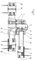
- the diaphragm valve shown in FIG. 1 has a lower housing part 1 with a medium flow channel 4 and an upper housing part 2.
- Both housing parts 1, 2 are made of a weldable plastic such as Made of polyethylene and connected to one another by means of screw connections 5, a membrane 3 made of an elastomer being arranged firmly clamped between the two housing parts 1, 2.
- an actuator 6 operable with a pressure medium is arranged in the upper housing part 2, the diaphragm 3 being firmly connected to a pressure piece 7 of the actuator 6.
- the pressure medium is preferably compressed air.
- the pressure piece 7 is guided in the upper housing part 2 in the longitudinal direction and secured against rotation.
- a pipe socket 8 is arranged on the upper housing part 2, which is firmly connected to the upper housing part 2 by a weld in a bore 9.
- the pipe socket 8 must also consist of the same weldable thermoplastic material type as the upper housing part 2, with polyethylene preferably being used for this.
- the pipe socket 8 can also be connected to the upper housing part 2 by an end-side butt welding, or there is also the possibility that the pipe socket 8 is firmly connected to the upper housing part 2 by one-piece production using the injection molding process.
- an electric welding sleeve 11 can then also be used to connect the diaphragm valve to a supply pipe 10 for the pressure medium for controlling the valve, as a result of which a simple and safe connection technique can be used.
- the diaphragm valve is mainly used for drinking water pipes or gas pipes, the high closing forces as with diaphragm valves are not required for industrial use, so that polyethylene can be used for the upper housing part 2 and the lower housing part 1, whereby another weldable plastic is also used can be, which is usually used in the gas and water supply.
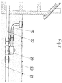
- FIG. 2 shows the use of a previously described diaphragm valve 20 in supply lines 21 for drinking water or gas to shut off a house supply line 22.
- the supply pipe 10 for the pressure medium leads from the membrane valve 20 arranged under the earth's surface 23 to the earth's surface 23 and is accessible there at any time.
- a compressed air bottle is connected to the accessible end of the supply pipe 10, with the compressed air actuating the actuator and closing the flow.
- the materials used and the use of the welding connection technology ensure simple and inexpensive manufacture of the diaphragm valve and its use in supply lines.
Landscapes
- Engineering & Computer Science (AREA)
- General Engineering & Computer Science (AREA)
- Mechanical Engineering (AREA)
- Physics & Mathematics (AREA)
- Fluid Mechanics (AREA)
- Fluid-Driven Valves (AREA)
- Valve Housings (AREA)
- Diaphragms And Bellows (AREA)
- External Artificial Organs (AREA)
- Lift Valve (AREA)
- Mechanically-Actuated Valves (AREA)
Abstract
Description
- Die Erfindung betriftt ein Membranventil aus Kunststoff, wie es im Oberbegriff von Anspruch 1 beschrieben ist.
- Versorgungsleitung aus Kunststoff für die Zuführung von Trinkwasser und Gas bestehen meist aus einem schweissbaren Kunststoff, vorzugsweise aus Polyethylen. Für die Absperrrung der Leitungen vor dem Hausanschluss werden Schieber verwendet, die mit einer meist in die Strassenoberfläche eingebauten Kupplung über ein Gestänge zu betätigen sind.
- Bekannt sind Membranventile, welche einen durch ein Druckmedium betätigbaren Stellantrieb aufweisen und somit fernbedienbar sind. Diese bekannten Ventile sind durch die verwendeten Materalien wie z.B. Polyvinylchlorid nur im IndustrieBereich verwendbar und somit nicht für den Einsatz im Versorungsbereich geeignet, da sie für die hier übliche direkte Verbindungstechnik mittels Schweissmuffen ungeeignet sind.
- Aufgabe der vorliegenden Erfindung ist die Schaffung eines Membranventils der eingangs genannten Art, welches einen direkten Anschluss für das Durchflussmedium mittels Schweissverbindungen an das Rohrleitungsnetz der Wasser- oder Gas-Versorgung ermöglicht, wobei auch der Anschluss der Steuerleitung beim Stellantrieb des Ventils ebenfalls auf die gleiche Art herstellbar sein soll.
- Erfindungsgemäss wird diese Aufgabe durch die kennzeichnenden Merkmale des Anspruches 1 gelöst.
- Besonders vorteilhafte Ausbildungen der Erfindung sind in den abhängigen Ansprüchen gekennzeichnet.
- Die Erfindung ist in der beiliegenden Zeichnung beispielsweise dargestellt und nachfolgend beschrieben. Es zeigen:
- Fig. 1
- eine Seitenansicht eines Membranventils teilweise im Schnitt und
- Fig. 2
- den Einbau eines Membranventils in einer Versorgungsleitung.
- Das in Fig. 1 gezeigte Membranventil weist ein Gehäuseunterteil 1 mit einem Medium-Durchflusskanal 4 und ein Gehäuseoberteil 2 auf. Beide Gehäuseteile 1, 2 sind aus einem schweissbaren Kunststoff wie z.B. Polyethylen hergestellt und mittels Schraubverbindungen 5 miteinander verbunden, wobei eine Membrane 3 aus einem Elastomer zwischen den beiden Gehäuseteilen 1, 2 fest eingespannt angeordent ist.
- Zur Betätigung der Membrane 3 ist im Gehäuseoberteil 2 ein mit einem Druckmedium betätigbarer Stellantrieb 6 angeordnet, wobei die Membrane 3 fest mit einem Druckstück 7 des Stellantriebes 6 verbunden ist. Vorzugsweise ist das Druckmedium Druckluft.
- Das Druckstück 7 ist im Gehäuseoberteil 2 in Längsrichtung verschiebbar geführt und gegen Verdrehen gesichert.
- Für die Zuführung des Druckmediums ist am Gehäuseoberteil 2 ein Rohrstutzen 8 angeordnet, welcher in einer Bohrung 9 steckend durch eine Schweissung fest mit dem Gehäuseoberteil 2 verbunden ist.
- Zur Herstellung dieser Muffen-Schweissung muss der Rohrstutzen 8 ebenfalls aus dem gleichen schweissbaren thermoplastischen Materialtyp wie das Gehäuseoberteil 2 bestehen, wobei hierfür vorzugsweise Polyethylen verwendet wird.
- Anstatt der Muffen-Schweissung kann der Rohrstutzen 8 auch durch eine stirnseitige Stumpf-Schweissung mit dem Gehäuseoberteil 2 verbunden werden oder es besteht auch die Möglichkeit, dass der Rohrstutzen 8 mit dem Gehäuseoberteil 2 durch einstückige Herstellung im Spritzgussverfahren fest verbunden ist.
- Durch die Verwendung von Rohren aus einem schweissbaren Thermoplast, wie z.B. aus Polyethylen kann dann auch zum Anschliessen des Membranventils an ein Zufuhrrohr 10 für das Druckmedium zur Steuerung des Ventils eine Elektro-Schweissmuffe 11 verwendet werden, wodurch eine einfache und sichere Verbindungstechnik angewendet werden kann.
- Das gleiche gilt für den Anschluss des Gehäuseunterteils 1 des Membranventils an die Rohrleitung 12 für das Durchflussmedium, wofür vorteilhafterweise ebenfalls Elektro-Schweissmuffen 13 verwendet werden.
- Da das Membranventil hauptsächlich für Trinkwasserleitungen oder Gasleitungen verwendet wird, sind nicht die hohen Schliesskräfte wie bei Membranventilen für die industrielle Verwendung erforderlich, sodass eine Verwendung von Polyethylen für das Gehäuseoberteil 2 und das Gehäuseunterteil 1 möglich ist, wobei auch ein ande-rer schweissbarer Kunststoff verwendet werden kann, welcher in der Gas- und Wasserversorgung üblicherweise Verwendung findet.
- Figur 2 zeigt die Verwendung eines vorgängig beschriebenen Membranventils 20 in Versorgungsleitungen 21 für Trinkwasser oder Gas zur Absperrung einer Hauszufuhrleitung 22.
- Von dem unter der Erdoberfläche 23 angeordneten Membranventil 20 führt das Zufuhrrohr 10 für das Druckmedium zur Erdoberfläche 23 und ist dort jederzeit zugänglich. Zum Absperren der Hauszufuhrleitung 22 wird an das zugängliche Ende des Zufuhrrohres 10 eine Druckluftflasche angeschlossen, wobei durch die Druckluft der Stellantrieb betätigbar ist und der Durchfluss geschlossen werden kann.
- Durch die verwendeten Materalien und die Anwendung der Schweiss-Verbindungstechnik ist eine einfache und kostengünstige Herstellung des Membranventils sowie dessen Verwendung in Versorungsleitungen gegeben.
Claims (10)
- Membranventil aus Kunststoff mit einem, einen Medium-Durchflusskanal aufweisenden Gehäuseunterteil, einem Gehäuseoberteil mit einem durch ein Druckmedium beaufschlagbaren Stellantrieb und einer zwischen den Gehäuseteilen eingespannten Membrane, dadurch gekennzeichnet, dass das Gehäuseunterteil (1) und das Gehäuseoberteil (2) aus einem schweissbaren thermoplastischen Kunststoff besteht wobei das Gehäuseunterteil (1) durch Schweissung mit den Rohrleitungen (12) für das Durchflussmedium verbindbar ist.
- Membranventil nach Anspruch 1, dadurch gekennzeichnet, dass das Gehäuseunterteil (1) und das Gehäuseoberteil (2) aus Polyethylen hergestellt sind.
- Membranvetil nach Anspruch 1 oder 2, dadurch gekennzeichnet, dass ein Rohrstutzen (8) für das Druckmedium aus einem schweissbaren thermoplastischen Kunststoff vorzugsweise aus Polyethylen besteht, und mittels einer Schweissverbindung mit dem Gehäuseoberteil (2) verbunden ist.
- Membranventil nach Anspruch 3, dadurch gekennzeichnet, dass der Rohrstutzen (8) in einer Bohrung (9) des Gehäuseoberteils (2) steckend durch eine Muffenschweissung mit dem Gehäuseoberteil (2) verbunden ist.
- Membranventil nach Anspruch 3, dadurch gekennzeichnet, dass der Rohrstutzen (8) stirnseitig mittels einer Stumpfschweissverbindung mit dem Gehäuseoberteil (2) verbunden ist.
- Membranventil nach Anspruch 1 oder 2, dadurch gekennzeichnet, dass der Rohrstutzen (8) mit dem Gehäuseoberteil (2) durch einstückige Herstellung im Spritzgussverfahren fest verbunden ist.
- Membranventil nach einem der Ansprüche 1 bis 6, dadurch gekennzeichnet, das das Gehäuseunterteil (1) mit der Rohrleitung (12) für das Durchflussmedium mittels Elektro-Schweissmuffen (13) fest verbindbar ist.
- Membranventil nach einem der Ansprüche 1 bis 6, dadurch gekennzeichnet, dass der Rohrstutzen (8) des Gehäuseoberteils (2) mit einem Zufuhrrohr (10) für das Druckmedium mittels einer Elektro-Schweissmuffe (11) fest verbindbar ist.
- Verwendung des Membranventil nach Anspruch 1 oder einem der Ansprüche 2 bis 8, bei Versorungsleitungen (21) für Trinkwasser oder Gas zur Absperrung einer Hauszufuhrleitung (22).
- Verwendung des Membranventils nach Anspruch 9, dadurch gekennzeichnet, dass von dem unter der Erdoberfläche angeordneten Membranventil (20) das Zufuhrrohr (10) für das Druckmedium bis zur Erdoberfläche verlegt wird wobei an dem Ende eine Druckluftflasche zur Absperrung des Membranventils (20) anschliessbar ist.
Applications Claiming Priority (2)
| Application Number | Priority Date | Filing Date | Title |
|---|---|---|---|
| CH2716/91 | 1991-09-13 | ||
| CH2716/91A CH685515A5 (de) | 1991-09-13 | 1991-09-13 | Membranventil aus Kunststoff und dessen Verwendung. |
Publications (2)
| Publication Number | Publication Date |
|---|---|
| EP0534111A1 true EP0534111A1 (de) | 1993-03-31 |
| EP0534111B1 EP0534111B1 (de) | 1998-10-07 |
Family
ID=4239993
Family Applications (1)
| Application Number | Title | Priority Date | Filing Date |
|---|---|---|---|
| EP92113653A Expired - Lifetime EP0534111B1 (de) | 1991-09-13 | 1992-08-11 | Membranventil aus Kunststoff und dessen Verwendung |
Country Status (5)
| Country | Link |
|---|---|
| EP (1) | EP0534111B1 (de) |
| AT (1) | ATE172010T1 (de) |
| CH (1) | CH685515A5 (de) |
| DE (1) | DE59209520D1 (de) |
| DK (1) | DK0534111T3 (de) |
Citations (3)
| Publication number | Priority date | Publication date | Assignee | Title |
|---|---|---|---|---|
| GB2068070A (en) * | 1980-01-21 | 1981-08-05 | Tennyson T M | Plumbing fittings |
| US4454893A (en) * | 1981-11-30 | 1984-06-19 | Puritan-Bennett Corp. | Low-noise diaphragm for use in exhalation valve |
| EP0185428A1 (de) * | 1984-12-17 | 1986-06-25 | Nederlandse Industriele Maatschappij NEFIT B.V. | Kugelventil ganz aus plastischem Material hergestellt |
-
1991
- 1991-09-13 CH CH2716/91A patent/CH685515A5/de not_active IP Right Cessation
-
1992
- 1992-08-11 DE DE59209520T patent/DE59209520D1/de not_active Expired - Fee Related
- 1992-08-11 EP EP92113653A patent/EP0534111B1/de not_active Expired - Lifetime
- 1992-08-11 AT AT92113653T patent/ATE172010T1/de not_active IP Right Cessation
- 1992-08-11 DK DK92113653T patent/DK0534111T3/da active
Patent Citations (3)
| Publication number | Priority date | Publication date | Assignee | Title |
|---|---|---|---|---|
| GB2068070A (en) * | 1980-01-21 | 1981-08-05 | Tennyson T M | Plumbing fittings |
| US4454893A (en) * | 1981-11-30 | 1984-06-19 | Puritan-Bennett Corp. | Low-noise diaphragm for use in exhalation valve |
| EP0185428A1 (de) * | 1984-12-17 | 1986-06-25 | Nederlandse Industriele Maatschappij NEFIT B.V. | Kugelventil ganz aus plastischem Material hergestellt |
Non-Patent Citations (2)
| Title |
|---|
| DURAPIPE: POLYETHYLENE PIPEWORK SYSTEMS (FIRMENPROSPEKT), 7. März 1991, Durapipe Glynwed Plastics Ltd, Northon Canes, Cannock, Staffordshire, GB * |
| DURAPIPE: THERMOPLASTIC VALVES (FIRMENPROSPEKT), 4. Oktober 1989, Durapipe Glynwed Plastics Ltd, Northon Canes, Staffordshire, GB * |
Also Published As
| Publication number | Publication date |
|---|---|
| CH685515A5 (de) | 1995-07-31 |
| DE59209520D1 (de) | 1998-11-12 |
| ATE172010T1 (de) | 1998-10-15 |
| DK0534111T3 (da) | 1999-06-21 |
| EP0534111B1 (de) | 1998-10-07 |
Similar Documents
| Publication | Publication Date | Title |
|---|---|---|
| DE68919356T2 (de) | Verfahren zur rohrreparatur. | |
| DE2145196C2 (de) | Absperrhahn mit einer den Betätigungszapfen umgreifenden Membrandichtung | |
| EP0023582A1 (de) | Säule für die Hochdruckflüssigkeitschromatographie und deren Verwendung | |
| DE69119539T2 (de) | Ersetzung von Hauptleitungen | |
| DE69319279T2 (de) | Austauschbares Quetschventil | |
| EP0093328A1 (de) | Anschluss-Formstück | |
| EP0493316A1 (de) | Vorrichtung zum Verbinden eines schweissbaren Kunststoff- oder Verbundrohres mit einem weiteren Leitungsteil | |
| DE69727108T2 (de) | Injektionsdübel zum Einpressen von Injektionsgut in Betonbauteile und Verbindungsvorrichtung | |
| CH201377A (de) | Vorrichtung zum Abschliessen von Leitungen. | |
| DE19529197A1 (de) | Entleerventil | |
| EP0534111B1 (de) | Membranventil aus Kunststoff und dessen Verwendung | |
| DE1750053C3 (de) | Doppelrohrbruchsicherheitsventil | |
| DE3102363C2 (de) | Pneumatisch gesteuertes Ventil | |
| DE3416109A1 (de) | Einrichtung zur schwenk- und loesbaren verbindung zweier winkelig zueinander verlaufenden rohrleitungen | |
| DE19537063C2 (de) | Volumenstromregler | |
| EP0677690B1 (de) | Muffenspiegeldichtung | |
| DE102018109998A1 (de) | Rohranschlusssystem und Verfahren zur Herstellung eines Rohranschlusses | |
| DE10150180A1 (de) | Halterung für eine Vorrichtung zum Belüften von Wasser | |
| DE4032118C2 (de) | ||
| DE2340942A1 (de) | Ventil mit einem rohrfoermigen metallgehaeuse | |
| EP0748977A2 (de) | Absperrvorrichtung für Rohrleitungen und Vorrichtung zum Setzen der Absperrvorrichtung | |
| DE1808766A1 (de) | Ventil | |
| DE19803901A1 (de) | Ventilsitz - Einsatz | |
| DE9412355U1 (de) | Absperrvorrichtung für Rohrleitungen zum Transport von flüssigen oder gasförmigen Medien | |
| DE10041840A1 (de) | Anbohrgerät |
Legal Events
| Date | Code | Title | Description |
|---|---|---|---|
| PUAI | Public reference made under article 153(3) epc to a published international application that has entered the european phase |
Free format text: ORIGINAL CODE: 0009012 |
|
| 17P | Request for examination filed |
Effective date: 19920818 |
|
| AK | Designated contracting states |
Kind code of ref document: A1 Designated state(s): AT BE CH DE DK ES FR GB IT LI LU NL PT SE |
|
| 17Q | First examination report despatched |
Effective date: 19960909 |
|
| GRAG | Despatch of communication of intention to grant |
Free format text: ORIGINAL CODE: EPIDOS AGRA |
|
| GRAG | Despatch of communication of intention to grant |
Free format text: ORIGINAL CODE: EPIDOS AGRA |
|
| GRAH | Despatch of communication of intention to grant a patent |
Free format text: ORIGINAL CODE: EPIDOS IGRA |
|
| ITF | It: translation for a ep patent filed | ||
| GRAH | Despatch of communication of intention to grant a patent |
Free format text: ORIGINAL CODE: EPIDOS IGRA |
|
| GRAA | (expected) grant |
Free format text: ORIGINAL CODE: 0009210 |
|
| AK | Designated contracting states |
Kind code of ref document: B1 Designated state(s): AT BE CH DE DK ES FR GB IT LI LU NL PT SE |
|
| PG25 | Lapsed in a contracting state [announced via postgrant information from national office to epo] |
Ref country code: GB Free format text: LAPSE BECAUSE OF FAILURE TO SUBMIT A TRANSLATION OF THE DESCRIPTION OR TO PAY THE FEE WITHIN THE PRESCRIBED TIME-LIMIT Effective date: 19981007 Ref country code: FR Free format text: LAPSE BECAUSE OF FAILURE TO SUBMIT A TRANSLATION OF THE DESCRIPTION OR TO PAY THE FEE WITHIN THE PRESCRIBED TIME-LIMIT Effective date: 19981007 Ref country code: ES Free format text: THE PATENT HAS BEEN ANNULLED BY A DECISION OF A NATIONAL AUTHORITY Effective date: 19981007 |
|
| REF | Corresponds to: |
Ref document number: 172010 Country of ref document: AT Date of ref document: 19981015 Kind code of ref document: T |
|
| REG | Reference to a national code |
Ref country code: CH Ref legal event code: NV Representative=s name: ROTTMANN, ZIMMERMANN + PARTNER AG Ref country code: CH Ref legal event code: EP |
|
| REF | Corresponds to: |
Ref document number: 59209520 Country of ref document: DE Date of ref document: 19981112 |
|
| PG25 | Lapsed in a contracting state [announced via postgrant information from national office to epo] |
Ref country code: SE Free format text: LAPSE BECAUSE OF FAILURE TO SUBMIT A TRANSLATION OF THE DESCRIPTION OR TO PAY THE FEE WITHIN THE PRESCRIBED TIME-LIMIT Effective date: 19990107 Ref country code: PT Free format text: LAPSE BECAUSE OF FAILURE TO SUBMIT A TRANSLATION OF THE DESCRIPTION OR TO PAY THE FEE WITHIN THE PRESCRIBED TIME-LIMIT Effective date: 19990107 |
|
| EN | Fr: translation not filed | ||
| GBV | Gb: ep patent (uk) treated as always having been void in accordance with gb section 77(7)/1977 [no translation filed] |
Effective date: 19981007 |
|
| REG | Reference to a national code |
Ref country code: DK Ref legal event code: T3 |
|
| PG25 | Lapsed in a contracting state [announced via postgrant information from national office to epo] |
Ref country code: LU Free format text: LAPSE BECAUSE OF NON-PAYMENT OF DUE FEES Effective date: 19990811 Ref country code: AT Free format text: LAPSE BECAUSE OF NON-PAYMENT OF DUE FEES Effective date: 19990811 |
|
| PLBE | No opposition filed within time limit |
Free format text: ORIGINAL CODE: 0009261 |
|
| PG25 | Lapsed in a contracting state [announced via postgrant information from national office to epo] |
Ref country code: LI Free format text: LAPSE BECAUSE OF NON-PAYMENT OF DUE FEES Effective date: 19990831 Ref country code: DK Free format text: LAPSE BECAUSE OF NON-PAYMENT OF DUE FEES Effective date: 19990831 Ref country code: CH Free format text: LAPSE BECAUSE OF NON-PAYMENT OF DUE FEES Effective date: 19990831 Ref country code: BE Free format text: LAPSE BECAUSE OF NON-PAYMENT OF DUE FEES Effective date: 19990831 |
|
| 26N | No opposition filed | ||
| BERE | Be: lapsed |
Owner name: GEORG FISCHER ROHRLEITUNGSSYSTEME A.G. Effective date: 19990831 |
|
| PG25 | Lapsed in a contracting state [announced via postgrant information from national office to epo] |
Ref country code: NL Free format text: LAPSE BECAUSE OF NON-PAYMENT OF DUE FEES Effective date: 20000301 |
|
| REG | Reference to a national code |
Ref country code: CH Ref legal event code: PL |
|
| REG | Reference to a national code |
Ref country code: DK Ref legal event code: EBP |
|
| NLV4 | Nl: lapsed or anulled due to non-payment of the annual fee |
Effective date: 20000301 |
|
| PG25 | Lapsed in a contracting state [announced via postgrant information from national office to epo] |
Ref country code: DE Free format text: LAPSE BECAUSE OF NON-PAYMENT OF DUE FEES Effective date: 20000601 |
|
| PG25 | Lapsed in a contracting state [announced via postgrant information from national office to epo] |
Ref country code: IT Free format text: LAPSE BECAUSE OF NON-PAYMENT OF DUE FEES;WARNING: LAPSES OF ITALIAN PATENTS WITH EFFECTIVE DATE BEFORE 2007 MAY HAVE OCCURRED AT ANY TIME BEFORE 2007. THE CORRECT EFFECTIVE DATE MAY BE DIFFERENT FROM THE ONE RECORDED. Effective date: 20050811 |