EP0534220A2 - Circuit de traitement de signal vidéo avec fonction d'agrandissement d'image - Google Patents
Circuit de traitement de signal vidéo avec fonction d'agrandissement d'image Download PDFInfo
- Publication number
- EP0534220A2 EP0534220A2 EP92115281A EP92115281A EP0534220A2 EP 0534220 A2 EP0534220 A2 EP 0534220A2 EP 92115281 A EP92115281 A EP 92115281A EP 92115281 A EP92115281 A EP 92115281A EP 0534220 A2 EP0534220 A2 EP 0534220A2
- Authority
- EP
- European Patent Office
- Prior art keywords
- video signal
- clock
- memory
- signal
- circuit
- Prior art date
- Legal status (The legal status is an assumption and is not a legal conclusion. Google has not performed a legal analysis and makes no representation as to the accuracy of the status listed.)
- Granted
Links
Images


Classifications
-
- H—ELECTRICITY
- H04—ELECTRIC COMMUNICATION TECHNIQUE
- H04N—PICTORIAL COMMUNICATION, e.g. TELEVISION
- H04N7/00—Television systems
- H04N7/01—Conversion of standards, e.g. involving analogue television standards or digital television standards processed at pixel level
-
- H—ELECTRICITY
- H04—ELECTRIC COMMUNICATION TECHNIQUE
- H04N—PICTORIAL COMMUNICATION, e.g. TELEVISION
- H04N7/00—Television systems
- H04N7/01—Conversion of standards, e.g. involving analogue television standards or digital television standards processed at pixel level
- H04N7/0117—Conversion of standards, e.g. involving analogue television standards or digital television standards processed at pixel level involving conversion of the spatial resolution of the incoming video signal
- H04N7/0122—Conversion of standards, e.g. involving analogue television standards or digital television standards processed at pixel level involving conversion of the spatial resolution of the incoming video signal the input and the output signals having different aspect ratios
-
- G—PHYSICS
- G06—COMPUTING OR CALCULATING; COUNTING
- G06T—IMAGE DATA PROCESSING OR GENERATION, IN GENERAL
- G06T3/00—Geometric image transformations in the plane of the image
- G06T3/40—Scaling of whole images or parts thereof, e.g. expanding or contracting
-
- H—ELECTRICITY
- H04—ELECTRIC COMMUNICATION TECHNIQUE
- H04N—PICTORIAL COMMUNICATION, e.g. TELEVISION
- H04N5/00—Details of television systems
- H04N5/222—Studio circuitry; Studio devices; Studio equipment
- H04N5/262—Studio circuits, e.g. for mixing, switching-over, change of character of image, other special effects ; Cameras specially adapted for the electronic generation of special effects
- H04N5/2628—Alteration of picture size, shape, position or orientation, e.g. zooming, rotation, rolling, perspective, translation
Definitions
- the present invention relates to techniques of video signal processing, and more particularly to a method and circuit arrangement for video signal processing suitable for use with a display apparatus which displays an image of a video signal such as a television signal through enlargement and compression to an arbitrary picture size.
- JP-A-3-11891 offers a method of using the whole screen area by display the standard video signal through the expansion in the vertical direction as shown in Fig. 3C.
- Fig. 4A is a conceptual circuit diagram showing the circuit arrangement for carrying out the above-mentioned prior art.
- a reference numeral 401 denotes an input terminal for the NTSC television signal
- 402 denotes an output terminal for the video signal with an attribute of converted aspect ratio
- 403 denotes a NTSC decoder which separates the NTSC television signal into a luminance and color difference signal
- 404 denotes a non-interlace conversion circuit which converts the signal into double-rated signal for progressive scanning
- 405 denotes a first memory circuit used for the time base conversion
- 406 denotes a second memory circuit used to determine the extracting position of the video signal
- 407 denotes a line calculation circuit which implements the image calculation for an upper and lower lines on the screen
- 408 and 409 denote a first and second selection switching circuits.
- the first memory circuit 405 is operated by application of a read clock which is higher than the write clock so as to compress the time axis, and the resulting video signal is supplied to the display unit through the a-contact of the second selection switching circuit 409.
- the video signal is prerecorded as a "squeezed signal" in which a circular image is reformed in a vertically elongated ellipsoidal image as shown in Fig.
- the video signal is fed through intact by way of the a-contact of the first selection switching circuit 408 and the b-contact of the second selection switching circuit 409, instead of using the first and second memory circuits.
- the video signal can be displayed to produce a picture of accurate shape on the display screen with a 16:9 aspect ratio as shown in Fig. 3E.
- a second memory circuit 406 having a large storage capacity is used to define the extraction area of picture and the picture is expanded in the vertical direction based on an interpolation process by the line calculation circuit 407.
- Fig. 4B shows the arrangement of the line calculation circuit 407.
- a reference numeral 410 denotes an input terminal for the video signal provided by the second memory circuit 406, 411 denotes an output terminal, 412 denotes a one-line delay memory circuit, 413 and 414 denote coefficient memories used to magnify the image of input signal at a fixed magnification factor, and 415 denotes an adder.
- the interpolation process implemented by the line calculation circuit 407 will be explained in detail in connection with Fig. 5.
- Columns (A) and (B) in Fig. 5 show proper levels and weighting factors or coefficient of scanning lines in magnifying a picture by 4/3 in this example through the interpolation of scanning lines.
- the video signal for the 4/3 magnification can be produced through a relatively simple filtering process for the factors, as will be appreciated from the Figure.
- Column (C) in Fig. 5 shows scanning lines on the input terminal 410, i.e., the output of the field memory circuit 406, indicating that the same scanning line is read out once in every four lines.
- Column (D) in Fig. 5 shows values in the second coefficient multiplier 414 which stores coefficients ⁇ to be multiplied to the scanning lines on the input terminal 410.
- FIG. 5 shows output scanning lines provided by the one-line delay memory 412.
- Column (F) in Fig. 5 shows coefficients (1- ⁇ ) in the first coefficient multiplier 413.
- Column (G) in Fig. 5 shows output signals of the adder 415.
- JP-A-3-60583 uses a deflection circuit for displaying a picture from a video signal of a movie picture size through the vertical expansion thereby to accomplish a display mode of Fig. 3C.
- the technique for a display mode shown in Fig. 3B through the compression of input video signal in the horizontal direction is conventionally based on the formation of a read clock from the write clock of the first memory circuit 405 by use of phase locked loop (PLL) circuits.
- PLL phase locked loop
- Described above is the prior art method of displaying a picture from a standard video signal of 4:3 aspect ratio with a display unit with a 16:9 aspect ratio.
- This prior art method is based on the expansion of picture in the vertical direction so that the resulting picture is displayed in the entire screen area of 16:9 aspect ratio.
- Video signals of movie pictures as shown in Fig. 3F include a variety of sizes of picture field, and when these signals are simply rendered the vertical expansion, the literal field or other crucial section of picture is cut off or a blanking portion at the top or bottom of picture is left unremoved in many cases.
- JP-A-3-11891 is devised for the vertical expansion mode to minimize the lost portion at the top and bottom of picture by switching the magnification factor between 4/3 and 5/4 for the first and second coefficient multipliers 413 and 414, it does not consider the horizontal expansion and compression of picture.
- An object of the present invention is to provide an enlarged-picture signal generating circuit arrangement for processing an input video signal to display on a display unit a picture with an aspect ratio different from that of a picture of the input video signal without incurring distortion of image by setting an expansion or compression coefficient optimal for the video signal.
- the term "enlargement of a picture” is intended to imply “compression of a picture” as well.
- Another object of the present invention is to provide a circuit arrangement for implementing compression display for an input picture without incurring the degradation of jitter preventive performance.
- Still another object of the present invention is to provide a display system which enables a common screen drive circuit to display with television signals of different television systems.
- an enlarged picture generating circuit based on one aspect of the invention comprises first clock generation means for producing a write clock which is synchronous with an input video signal that is adapted to progressive scanning, second clock generation means for producing a read clock having a stable frequency set to about 4/3 times the write clock frequency, memory means for storing temporarily the input video signal in response to the write clock and reading out the stored contents intermittently in response to the read clock, spatial filter means for producing a video signal of an enlarged picture by rendering filtering to the output signal of the memory means, and enlargement control means for controlling the first and second clock generation means, memory means, and spatial filter means.
- the write clock for the memory means By making the write clock for the memory means synchronous with the input video signal and setting the read clock frequency to be about 4/3 times the write clock frequency, it becomes possible to render the time-base compression to the video signal. By using a stable read clock which is asynchronous with the input video signal, it becomes possible at the same time to reduce jitters which emerge during the picture enlarging processing.
- Reading of the video signal out of the memory means is controlled in accordance with the control signals from the enlargement control means in units of line and picture element, and it thereby enables enlarging of a picture as to the video signal in both vertical and horizontal directions.
- the interval of the halt of reading and the starting position of reading are determined in accordance with the enlarging coefficient or factor and enlarging position which are set in the enlargement control means.
- the spatial filter means eliminates distortion of the signal picture which has been enlarged using the memory means.
- the spatial filter means has a role of a filter of vertical direction which produces a new scanning line from the current signal and line-delayed signal and a role of a filter of horizontal direction which produces a new picture element from the current signal and picture-element-delayed signal.
- the spatial filter means is controlled by the enlargement control means.
- the video signal of a picture which has been enlarged to the picture size determined by the enlargement control means is now a stable video signal including less jitters, and it can be supplied to display on a display unit with a 16:9 aspect ratio.
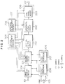
- Fig. 1 shows a display circuit in accordance with an embodiment of the present invention.
- a reference numeral 101 denotes an input terminal for a video signal which is subject to progressive scanning
- 102 denotes an output terminal
- 103 denotes an input terminal for a clock signal
- 109 denotes an input terminal for a sync signal
- 100 is a memory device used for the expanding or enlarging operation for the input video signal
- 104 and 105 denote first and second memory circuits which are included in the memory device 100 and operative to write and read data in response to different clocks
- 106 denotes a spatial filter circuit which implements the computation of interpolation in the vertical and horizontal directions for the video signal (picture)
- 107 denotes an expansion or enlargement control circuit which controls the first and second memory circuits and spatial filter circuit
- 108 denotes a synchronizing circuit which supplies clock signals to these circuits.
- the video signal of progressive scanning received on the input terminal 101 is rendered a vertical expansion by the first memory circuit 104 and the horizontal expansion by the second memory circuit 105 through the read/write operation under control of the circuits 107 and 108.
- Enlargement of picture is carried out by reading out the same line of a frame of video signal more than once for the vertical direction and reading out the same picture element on a line more than once for the horizontal direction.
- the resulting video signal of the vertically and horizontally expanded picture is subjected to filtering by the spatial filter 106 so that a picture displayed based on the output of the filter 106 appears smooth and natural.
- a reference numeral 201 denotes a vertical filter circuit which produces a new scanning line from two original scanning lines
- 202 denotes a horizontal filter circuit which produces a new picture element from two original picture elements
- 203 denotes a side panel signal inserting circuit which inserts another video signal
- 204 denotes a vertical expansion control circuit which controls the first and second memory circuits 104, 105, vertical filter circuit 201 and side panel signal inserting circuit 203 based on a desired expansion factor
- 205 denotes a horizontal expansion control circuit which controls the second memory circuit 105, horizontal filter circuit 202 and side panel signal inserting circuit 203 based on a desired expansion factor
- 206 denotes a first clock generation circuit which produces a first clock having a stable frequency which is substantially equal to the frequency of the clock received on the input terminal 103
- 207 denotes a second clock generation circuit which produces a second clock having a frequency which
- the first memory circuit 104 serves to determine a vertical range of expansion in a picture corresponding to the input video signal, suspend the memory read-out operation in the period line depending on the expansion coefficient, and convert the video signal which includes gitters into a stable video signal.
- Fig. 6 shows the principle of expansion in the vertical direction, i.e., expansion of scanning lines. Shown in columns (A) through (F) in Fig. 6 is the operation of the first memory circuit 104.
- Fig. 6 is assumed a side view of the television screen, with scanning lines being represented by circles labeled by alphabetic characters therein such as a, d.
- Shown by (A) in Fig. 6 is the position of the vertical sync signal in the input video signal. Shown by (B) in Fig. 6 is the positions a-p of scanning lines of the video signal received on the input terminal 101.
- the vertical expansion control circuit 204 sets the write reset signal (pulse) for the first memory circuit 104 to the position shown in column (C) in Fig. 6. Accordingly, the write address of the first memory circuit 104 is initialized to zero for the position of scanning line d, and sequential writing of the video signal for enlargement is performed from this position.
- Shown by (E) in Fig. 6 is a gate signal for the read clock.
- the memory read clock is disabled so that read-out of data is suspended for a period of one line.
- a gate-off control signal is applied to the first memory circuit once every four lines.
- the first memory circuit 104 determines the range of expansion and the period of scanning line expansion, and the signal shown by (F) in Fig. 6 is read out of the first memory circuit 104.
- Symbol "X" in column (F) in Fig. 6 indicates absence of read-out data. Since the first memory circuit 104 operates on the read clock which is derived from the stable first clock produced by the first clock generation circuit 206, the output video signal from the memory does not include gitters.
- the second memory circuit 105 implements the time-base conversion and reproduction of data during the period while the first memory circuit 104 is suspending the read-out operation.
- Fig. 7A shows an example of the detailed arrangement of the second memory circuit 105
- Figs. 7B to 7I show the principle of operation of the circuit.
- Fig. 7A shows an example of the detailed arrangement of the second memory circuit 105
- Figs. 7B to 7I show the principle of operation of the circuit.
- a reference numeral 701 denotes an input terminal for receiving the signal from the first memory circuit 104
- 702 denotes an output terminal
- 703 denotes an input terminal for receiving the write clock from the first clock generation circuit 206
- 704 denotes an input terminal for receiving the read clock from the second clock generation circuit 207
- 705 and 706 denote input terminals for the write reset signal and read reset signal
- 707 and 708 denote input terminals for the write enable signal
- 709 denotes an input terminal for the output control signal
- 710 and 711 denote respectively memories each having a one-line capacity
- 712 is a selection switching circuit.
- FIG. 7B shows an output signal of the first memory circuit 104, in which a waveform of data is absent once every four lines for the implementation of 4/3 magnification.
- Fig. 7C shows write reset and read reset signals which are received on the input terminals 705 and 706 and used to reset the internal memories 710 and 711. The write address and read address of the memories are reset to address 0 by these signals.
- Fig. 7D and Fig. 7G show write control signals for the internal memories 710 and 711, which inhibit data from being written to the memories when the input data is absent.
- Fig. 7E shows an active period of the read clock, which has a frequency about 4/3 times the write clock frequency. The read clock is produced by a PLL circuit in the second clock generation circuit 207.
- Data read out of the internal memories 710 and 711 includes data pieces which have been read recurrently for the line on which input signal is missing as shown in Fig. 7F and Fig. 7H.
- the selection switching circuit 712 operates to switch in accordance with an output control signal of Fig. 7I, and the signal which is compressed in the horizontal direction is produced for the scanning lines shown in column (G) of Fig. 6.
- the internal arrangement of the second memory circuit 105 which has been explained in detail in connection with Fig. 7A, is not limited to this example, but it will be apparent to those skilled in the art that the circuit can be configured with a single line memory by making a displacement in the positional relation of the write reset and read reset signals, for example.
- the video signal is compressed in the horizontal direction and the same line is written twice for every three lines for the vertical direction, and thereby an enlarged picture is produced.
- filtering in the vertical direction is needed and this is carried out by the vertical filter circuit 201.
- Fig. 8 shows an example of the detailed arrangement the vertical filter circuit 201.
- a reference numeral 801 denotes an input terminal for receiving the signal from the second memory circuit 105
- 802 denotes an output terminal
- 803 denotes an input terminal for producing a combining coefficient depending upon the expansion factor provided by the vertical expansion control circuit 204
- 806 denotes an input terminal for supplying a write control signal
- 804 denotes a one-line delay memory
- 805 denotes a combining circuit which combines input and output signals of the one-line delay memory.
- An input signal from the input terminal 801 is shown in column (G) of Fig. 6.
- the signal shown by (E) of Fig. 6 is used as a write control signal for the one-line delay memory, and it suspends writing once every four lines.
- the output signal of the one-line delay memory 804 is as shown by (H) in Fig. 6.
- a combining coefficient is produced by the vertical expansion control circuit 204, and in this example of 4/3 magnification, the factor cycles at a 4-line period which is equal to the read suspension period of the first memory circuit 104.
- the vertical filter circuit 201 has its output signal compressed on the time-base horizontally and filtered in the vertical direction, resulting in a video signal representing a smoothly expanded picture. At this time point, the picture has elongated in the vertical direction. To eliminate this distortion, the video signal needs to be processed such that the corresponding picture is expanded in the horizontal direction by using the second memory circuit 105 and horizontal filter circuit 202. Although the operation of the second memory circuit 105 has been explained on Fig. 7 on assumption that the picture is not expanded horizontally, the following explains the operation in more detail for the case of horizontal expansion.
- Figs. 9A-9H show in a set of waveform diagrams the detailed operation of the second memory circuit 105 when the horizontal expansion takes place.
- Shown in Fig. 9A is an example of the video signal introduced through the input terminal 701 of Fig. 7A, and the signal consists of a blanking period and a picture period.
- Shown in Fig. 9B is a write reset signal, and shown by 9C is a write clock.
- the write clock is produced from the stable first clock provided by the first clock generation circuit.
- the write clock is variable for its suspension position and period depending on the range (position) of expansion so that the video signal to be expanded as to its picture is stored correctly in the memory. For example, for expanding the signal from a point a of Fig. 9A, the clock is suspended from the blanking end position to the point a . Accordingly, when the contents of the memory are read out sequentially in response to this write clock, the signal of the point a is delivered immediately after the blanking period.
- Fig. 9E and Fig. 9F show a read reset signal and a read clock, respectively.
- the read clock is produced from the second clock having a frequency about 4/3 times the write clock which is produced by the second clock generation circuit 207.
- the read clock is temporally interrupted by a gate circuit in accordance with the expansion factor.
- Fig. 9G one out of four clocks is disabled and the signal is expanded for its specified picture portion as shown in Fig. 9H. This expansion is based on double writing of pixel (picture element) for every several pixels, and it is not a smooth expansion.
- the read clock is applied intact, and data of the blanking period is not expanded.
- the horizontal filter circuit 202 has a role of smoothing the signal, which has been expanded horizontally by the second memory circuit 105, through the filtering period.
- Fig. 10A shows an example of the detailed arrangement of the horizontal filter circuit 202.
- a reference numeral 1001 denotes an input terminal for receiving the signal from the vertical filter circuit 201
- 1002 denotes an output terminal
- 1003 denotes an input terminal for receiving the control signal from the horizontal expansion control circuit 205
- 1004 and 1006 denote one-pixel delay circuits (line memories), respectively
- 1005 denotes a selector switching circuit
- 1007 denotes a combining circuit which combines a signal from the input terminal 1001 with a signal from the delay circuit 1006 to produce a new pixel signal.
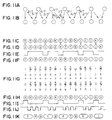
- Figs. 11A to 11K the operation of the circuit of Fig. 10A by taking another example of vertical expansion by 7/5 which is slightly more difficult than the previous example of 4/3 expansion.
- the video signal is stored in the second memory circuit 105 twice for two pixels out of seven pixels, and the signal of increased pixels is applied to the input terminal 1001.
- Fig. 11C shows an input video signal. Shown by 11A and 11B are the level of original pixels and the level of new pixels before and after the 7/5 expansion.
- the selector switching circuit 1005 makes switching between the original signal and one-pixel delayed signal in accordance with a control signal shown in Fig. 11E for producing the new interpolated pixels. Shown in Fig. 11F is an output signal of another delay circuit 1006 which delays by one pixel the signal selected by the the selector 1005.
- the original signal of Fig. 11C is replaced with a one-pixel-delayed signal shown in Fig. 11D in accordance with the control signal shown in Fig. 11E, for example, so as to produce a new signal shown in Fig. 11F, and the new signal is entered to the combining circuit 1007 thereby to produce interpolated pixels of the correct level shown in Fig. 11G.
- M/N where M and N are natural numbers
- n ⁇ M-1 ⁇ n-1 where n is an natural number
- a delay circuit as shown in Fig. 10A is used to obtain correct pixels.
- Fig. 10B shows another example of the detailed arrangement of the horizontal filter circuit 202.
- a reference numeral 1008 denotes a gate circuit
- 1009 is an input terminal for the clock
- remaining portions are the same as the previous example of Fig. 10A.
- the gate circuit 1008 interrupts the clock from the input terminal 1009 in accordance with the control signal from the input terminal 1003 thereby to hold pixels.
- the operation is equivalent to that of the circuit shown in Fig. 10A.
- Fig. 11I shows a gate signal which disables or suspends the clock
- Fig. 11J shows a gated clock
- Fig. 11K shows an output signal of the delay circuit 1004.
- the circuit arrangement of Fig. 10B is capable of dealing with the case of n equal to or greater than two based on the control signal from the input terminal 1003, and accordingly it allows horizontal expansion of arbitrary factor.
- the arrangement of the horizontal filter 202 is not limited to the foregoing example, but it will be appreciated for those skilled in the art that the horizontal filter can basically be served by any circuit arrangement which produces a delay time to meet the clock suspension and a combined output in compliance with the expansion factor.
- Table 1 is a list of factors of the combining circuit for accomplishing the vertical expansion by one to two fold, and Table 2 shows the 8-bit approximation.
- the expansion factor is defined to be M/N (where N is a natural number smaller than or equal to 8, and M is a natural number smaller than or equal to 15), there are 23 possible expansion factors which can be set.
- Table 1 shows ten factors among them.
- the control signals ⁇ and ⁇ of the combining circuit 805 are 8-bit signals for example, ⁇ (1) through ⁇ (15) have values shown in Table 1 based on the approximation of the expansion factor as M/N ⁇ 256/L (0 ⁇ L ⁇ 255, L is an integer).
- Table 2 shows the approximated expansion factors and values of ⁇ (n) which can be expressed by eight bits.
- the period of ⁇ (n) is given by M, and the value of ⁇ (n) is expressed by the following Expression (1).
- f(x) is a function taking the decimal part of x
- n is an integer in the range of 0 ⁇ n ⁇ M-1 .
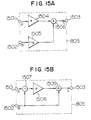
- Fig. 15A Examples of the combining circuit 805 and combining coefficient generation circuit will be explained in connection with Fig. 15A, Fig. 15B and Fig. 16.
- reference numerals 1501 and 1502 denote input terminals of the combining circuit 805, 1503 denotes an output terminal, 1504, 1505 and 1508 denote first, second and third factor multipliers, 1506 and 1509 denote first and second adders, and 1507 denotes a subtracter.
- the combining circuit shown in Fig. 15A receives signals A and B on the input terminals 1501 and 1502, and delivers a combined output C which is expressed by the following Expression (2).
- the combining circuit shown in Fig. 15B delivers a combined output which is expressed by Expression (3).
- C ⁇ A+(1- ⁇ )B (2)
- C ⁇ (A-B)+B (3)
- the combining circuit 805 shown in Fig. 15A and Fig. 15B can be arranged relatively simply by determining the combining coefficient ⁇ .
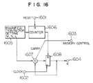
- Fig. 16 shows a factor generation circuit which produces the combining coefficient ⁇ .
- a numeral 1601 denotes an input terminal for the reset signal
- 1602 denotes an input terminal for clock which is used to update the combining coefficient ⁇
- 1603 denotes an output terminal for the control signal which controls writing and reading of the first and second memory circuits 104 and 105
- 1604 denotes an output terminal for the combining coefficient ⁇
- 1605 denotes an expansion factor setting circuit which determines the constant L depending on the magnification factor M/N
- 1606 denotes a divide-by-M counter
- 1607 denotes an adder
- 1608 denotes a latch circuit.
- the expansion factor setting circuit 1605 evaluates the value of L of 256/L which is close to M/N, calculates the value of K which is equal to (256-L)/256, and delivers the result to the adder 1607.
- the clock received on the input terminal 1602 is a clock having a one-line period in the case of vertical expansion, or it is a pixel-wise clock in the case of horizontal expansion.
- the adder 1607 has its output latched in the latch circuit 1608 so that the latched value is updated, and it is delivered as a combining coefficient ⁇ .
- the combining coefficient ⁇ is initialized cyclically at an interval of M by the counter 1606. Shown in Fig. 16 is an example of the circuit which sets the combining coefficient ⁇ and control timing of memory, and this circuit is capable of setting the values of ⁇ (n) shown in Table 1 and the system which can select the expansion factor arbitrarily can be configured by use of the circuit.
- vertical expansion by the first memory 103 and time-base compression and horizontal expansion by the second memory 104 can be controlled independently, and accordingly the distortion of the input video signal can be corrected.
- a standard television signal NTSC, etc.
- NTSC high-definition television signal
- Fig. 3D an input signal shown in Fig. 3D
- the converted standard television signal which is derived from a high-definition television signal, is displayed without distortion on a wide display screen with the 16:9 aspect ratio.
- Elimination of the distortion caused by the frequency conversion at the television system converting process and correction of horizontal 12/11 expansion, which need to be done inherently in the high-definition television receiver, are carried out at a time according to this embodiment, and consequently the circuit is simplified and a displayed picture without distortion can be offered.
- a numeral 1201 denotes an input terminal for a video signal
- 1202 denotes an image processing circuit which converts the input video signal into a digital signal in the form of progressive scanning
- 1203 denotes a display unit such as a CRT
- 1204 denotes a sync processing circuit including a PLL circuit for implementing a sync processing for the input video signal
- 1205 denotes a deflection circuit which drives a display unit
- the synchronizing circuit 1204 for producing a write clock for the first memory circuit 104, a second clock generation circuit 212 for producing a read clock for the second memory circuit 105 and a deflection circuit for producing a sync signal of the display unit 1203 include three PLL systems, respectively.
- these PLL circuits are cascade-connected, a large jitter, if exist in the input signal, is displayed by being emphasized due to the response time lag of these PLL circuits.
- the first clock generation circuit 211 is formed of an independent clock generation circuit using a crystal oscillator or the like, which enables the generation of a stable clock, and therefore, it does not propagate the jitter to the succeeding-stage circuit having two PLL systems. Namely, the read/write clock for the memory other than the write clock of the memory for the input video signal which has been converted into a digital signal in this system is stabilized as mentioned above, and consequently the amount of jitter created initially by the sync processing circuit 1204 does not increase:
- Fig. 13 shows an example of the arrangement of the memory circuit 104 and its peripheral circuitry for preventing this problem.
- a numeral 1301 denotes an input terminal for the video signal
- 1302 denotes an output terminal
- 1303 and 1304 denote vertical sync signal and clock supplied by the sync processing circuit 1204
- 1305 denotes a field memory
- 1306 and 1307 denote counters
- 1308 and 1309 denote decoders
- 1310 denotes a delay circuit, and remaining portions are identical to the arrangement of Fig. 2.
- a write clock for the field memory 1305 is a clock which is received on the input terminal 1303 and synchronous with the video signal, and at the same time, the write clock is a clock for the counter 1306.
- the read clock for the field memory 1305 is the stable clock produced by the clock generation circuit 211, and it is also supplied to the counter 1307.
- the counters 1306 and 1307 have their count values decoded by the decoders 1308 and 1309, and the decoded results become the write reset and read reset signals for the field memory 1305.
- a general video signal including a large jitter deviates from the stable clock as much as two lines in a field at most.
- the counter 1306 for writing and counter 1307 for reading are reset through the rendition of a delay as much as several lines while retaining the phase relation of the vertical sync signal received on the input terminal 1304, and therefore the problem of memory caused by the difference in frequency between the write clock and read clock can be eliminated.
- the counter 1307 for reading is reset independently of the clock of reading supplied by the clock generation circuit 211, and the horizontal sync signal for display produced by decoding the count value of the counter 1307 does not maintain the periodicity at the time of resetting. That is, it is necessary to improve the response or follow-up capability of the deflection circuit in the display unit to the horizontal sync signal so that the video signal does not fall disordered.
- circuit arrangements shown in Fig. 12 and Fig. 13 are capable of producing a video signal of high-quality picture even for an input signal containing much jitters.
- Figs. 17A to 17I are illustrations for providing two-fold enlargement of a picture portion in a bottom left zone on a screen.
- Fig. 17A shows an input vertical sync signal
- Fig. 17C shows an input picture.
- Fig. 17B shows a disorder of clock caused by the sync signal.
- Figs. 17D, 17E and 17F show results of expansion in accordance with the conventional method, in which Fig. 17D indicates an output vertical sync signal, Fig. 17E indicates the disordered clock, and Fig. 17F indicates an output picture. Because of a single clock system, the clock shown in Fig. 17F has the same disorderliness as that of Fig. 17B. On this account, the expanded video signal causes the resulting picture to distort at the vertical position corresponding to the disorderly clock portion. In order to eliminate this defect, the conventional method needs to use a memory of one field or more specialized for this purpose.
- Figs. 17G, 17H and 17I The expansion based on the inventive signal processing is shown in Figs. 17G, 17H and 17I.
- Fig. 17G shows an output vertical sync signal
- 17H shows an ordered clock
- Fig. 17I shows an output picture.
- the inventive method reads out the video signal from the temporary memory in response to the stable clock shown in Fig. 17H, and consequently the disorderliness of video signal caused by the input sync signal shown in Fig. 17A is eliminated and the video signal is rid of disorderliness in the entire magnified or enlarged picture area.
- the clock frequency of the clock generation circuit 211 is very close to the clock frequency of the sync processing circuit 1204.
- the stable clock oscillation frequency of the first clock generation circuit 211 is set to be 8fsc, the line frequency automatically becomes about 31.5 kHz which is the double-rated horizontal frequency of NTSC system.
- a television system of a wide display screen is intended for the prevalence of the high-definition television, and therefore it must be compatible with the high-definition television system.
- the display unit is designed to operate in two modes at a horizontal deflection frequency of 31.5 kHz for the double-rated NTSC system and of 33.75 kHz for the high-definition television system so that it is compatible with the input signal of the high-definition system.
- the stable clock frequency for the first clock generation circuit 211 being set to about 30.7125 MHz
- the horizontal frequency which meets 910 pixels is about 33.75 kHz which coincides with the horizontal frequency of high-definition television, and therefore, it is no more necessary to design the deflection system operating in two modes.
- the first memory circuit 104 has a faster read clock relative to the write clock, and a memory capacity of at least 40 lines will be required.
- the number of scanning lines increases from 525 to about 562. This is equivalent to the reduction in the interval of scanning lines and the displayed picture is compressed in the vertical direction.
- the degree of this distortion is 525/562.5 ⁇ 0.93. Accordingly, if it is intended to drive the display unit always at the horizontal sync frequency of high-definition television, the video signal is expanded by 562.5/525 in the vertical direction based on the foregoing technique. For example, through the vertical expansion by about 16/15, it becomes possible to display a video signal without distortion on a display unit of high-definition television. Accordingly, the deflection circuit can be designed to meet a single frequency, while retaining the inherent performance, whereby the convergence circuit and high-voltage circuit can be simplified and the cost of the system can be lowered.
- an input video signal with the 4:3 aspect ratio is rendered the temporary time-base compression by the second memory circuit 105 and thereafter, it is expanded at an arbitrary expansion factor.
- the vertical filter circuit 201 and horizontal filter circuit 202 can operate independently and the vertical expansion control circuit 209 and horizontal expansion control circuit 210 can operate independently, and therefore the expansion factors can be determined independently for the vertical direction and horizontal direction.
- the video signal in term of a picture is expanded after it has been compressed on the time-base in the horizontal direction by the second memory circuit 105.
- the time-base compression is not carried out prior to the horizontal expansion, it is necessary to have a horizontal reduction when the expansion factor is 4/3 or smaller or otherwise have a horizontal expansion. Since the signal is always expanded in the vertical direction in this case, a complex control circuit is needed.
- the horizontal expansion is controlled by the same control circuit irrespective of the expansion factor, and the system can be simplified.
- Fig. 14 shows another embodiment of the present invention. All functional blocks in the Figure are identical to those of the preceding embodiment of Fig. 2.
- the first memory circuit 104 operates on the write clock and read clock which are different, and particularly it uses a stable clock for reading. However, when the write clock and read clock are different, it is necessary to correct the deviation between the write and read clocks through the forced resetting, as has been explained in the previous embodiment. This operation creates a discontinuity in the sync signal, which could develop a blurred picture. This embodiment prevents the discontinuity of sync circuit by using the same clock for writing and reading for the first memory 104.
- the clock generation circuit 1401 produces a clock having a frequency about 4/3 times the one produced with a PLL circuit from the first clock, and no discontinuity occurs in the sync signal. According to this embodiment, an expanded video signal without sync disorder can be displayed on a display unit with the 16:9 aspect ratio.
- a video signal of a 4:3 aspect ratio picture is provided to display on a display unit with a 16:9 aspect ratio through expansion or compression signal processings which meet the feature of the video signal, whereby the display screen with the 16:9 aspect ratio can be used efficiently.
- the inventive circuit arrangement can be applied to display units with a 4:3 aspect ratio and also to video signals which include a distortion from the beginning.
Landscapes
- Engineering & Computer Science (AREA)
- Multimedia (AREA)
- Signal Processing (AREA)
- Physics & Mathematics (AREA)
- General Physics & Mathematics (AREA)
- Theoretical Computer Science (AREA)
- Computer Graphics (AREA)
- Television Systems (AREA)
- Controls And Circuits For Display Device (AREA)
- Studio Circuits (AREA)
Applications Claiming Priority (2)
| Application Number | Priority Date | Filing Date | Title |
|---|---|---|---|
| JP3247292A JP3034659B2 (ja) | 1991-09-26 | 1991-09-26 | 拡大画面表示回路及びそれに用いられる水平フィルタ回路 |
| JP247292/91 | 1991-09-26 |
Publications (3)
| Publication Number | Publication Date |
|---|---|
| EP0534220A2 true EP0534220A2 (fr) | 1993-03-31 |
| EP0534220A3 EP0534220A3 (en) | 1993-06-09 |
| EP0534220B1 EP0534220B1 (fr) | 1997-08-13 |
Family
ID=17161267
Family Applications (1)
| Application Number | Title | Priority Date | Filing Date |
|---|---|---|---|
| EP92115281A Expired - Lifetime EP0534220B1 (fr) | 1991-09-26 | 1992-09-07 | Circuit de traitement de signal vidéo avec fonction d'agrandissement d'image |
Country Status (5)
| Country | Link |
|---|---|
| US (1) | US5276515A (fr) |
| EP (1) | EP0534220B1 (fr) |
| JP (1) | JP3034659B2 (fr) |
| KR (1) | KR950009449B1 (fr) |
| DE (1) | DE69221569T2 (fr) |
Cited By (8)
| Publication number | Priority date | Publication date | Assignee | Title |
|---|---|---|---|---|
| EP0624975A1 (fr) * | 1993-05-14 | 1994-11-17 | Sony Corporation | Traitement de signal vidéo associé à un système de télévision |
| WO1995034989A1 (fr) * | 1994-06-13 | 1995-12-21 | Philips Electronics N.V. | Compression horizontale de l'image dans un recepteur de television a ecran large |
| EP0865020A3 (fr) * | 1997-02-24 | 1999-05-12 | Paradise Electronics, Inc. | Méthode et dispositif de retaillage d'une image |
| EP0803855A3 (fr) * | 1996-04-23 | 1999-06-16 | Hitachi, Ltd. | Processeur pour convertir le nombre de pixels d'un signal vidéo et appareil d'affichage utilisant ce processeur |
| US7071992B2 (en) | 2002-03-04 | 2006-07-04 | Macronix International Co., Ltd. | Methods and apparatus for bridging different video formats |
| DE19849387B4 (de) * | 1997-11-07 | 2007-02-15 | Elmo Company Ltd. | Verfahren zum Erzeugen eines Signals für ein vergrößertes Bild durch Verwenden eines Feldspeichers |
| EP2164065A4 (fr) * | 2007-07-04 | 2010-11-10 | Panasonic Corp | Dispositif à changement de mode |
| CN115482758A (zh) * | 2021-06-15 | 2022-12-16 | 瑞昱半导体股份有限公司 | 显示系统、显示面板控制芯片与相关的信号传输切换方法 |
Families Citing this family (21)
| Publication number | Priority date | Publication date | Assignee | Title |
|---|---|---|---|---|
| EP0586218B1 (fr) * | 1992-09-01 | 1998-07-22 | Canon Kabushiki Kaisha | Appareil de traitement d'images |
| KR960015397B1 (ko) * | 1993-03-17 | 1996-11-11 | 엘지전자 주식회사 | 사이드컷 모드 및 상하절단 모드를 적용한 고화질 티브이신호 변환회로 |
| JP3231142B2 (ja) * | 1993-06-18 | 2001-11-19 | 株式会社日立製作所 | 映像圧縮拡大回路及び装置 |
| JP2705547B2 (ja) * | 1993-12-16 | 1998-01-28 | 日本電気株式会社 | 画像縮小装置 |
| TW269091B (fr) * | 1993-12-22 | 1996-01-21 | Matsushita Electric Industrial Co Ltd | |
| US5943097A (en) * | 1993-12-24 | 1999-08-24 | Canon Kabushiki Kaisha | Image processing means for processing image signals of different signal formats |
| EP1307056B1 (fr) * | 1995-06-30 | 2004-10-06 | Mitsubishi Denki Kabushiki Kaisha | Dispositif de conversion de balayage avec une résolution verticale améliorée et un dispositif de réduction du scintillement |
| DE19640010A1 (de) * | 1996-09-27 | 1998-04-09 | Sony Deutschland Gmbh | Verfahren und Einrichtung zum vertikalen Zoomen eines 4:3 Fernsehbildes in einem Breitbild-Fernsehempfänger mit entsprechendem Decoder |
| US5796392A (en) | 1997-02-24 | 1998-08-18 | Paradise Electronics, Inc. | Method and apparatus for clock recovery in a digital display unit |
| DE19717140A1 (de) * | 1997-04-23 | 1998-10-29 | Thomson Brandt Gmbh | Verfahren zur Formatumwandlung von Bildern sowie Vorrichtung zur Durchführung des Verfahrens |
| JP3687269B2 (ja) * | 1997-05-08 | 2005-08-24 | ブラザー工業株式会社 | 画像処理装置 |
| US6259470B1 (en) * | 1997-12-18 | 2001-07-10 | Intel Corporation | Image capture system having virtual camera |
| US6133960A (en) * | 1998-06-26 | 2000-10-17 | Lsi Logic Corporation | Field-based upsampling method for performing zoom in a digital video system |
| KR100614788B1 (ko) * | 1998-12-22 | 2006-08-25 | 마쯔시다덴기산교 가부시키가이샤 | 영상 신호 재생 장치 |
| KR20040022737A (ko) * | 2002-09-05 | 2004-03-18 | (주)씨앤에스 테크놀로지 | 동영상 부호기의 전처리 회로 및 방법 |
| US7505636B2 (en) * | 2004-03-04 | 2009-03-17 | Broadcom Corporation | System and method for two-pass interpolation for quarter-pel motion compensation |
| US20060059514A1 (en) * | 2004-09-10 | 2006-03-16 | Eric Hsiao | Method and apparatus for utilizing blank space on a high definition television screen |
| JP4408836B2 (ja) * | 2005-05-30 | 2010-02-03 | キヤノン株式会社 | 画像処理装置及びその制御方法、プログラム |
| KR100761834B1 (ko) * | 2006-01-13 | 2007-09-28 | 삼성전자주식회사 | 화면의 라인들을 복수개의 메모리에 나누어 저장하는비디오 디코딩 장치, 비디오 디코딩 방법 및 기준화면 저장방법 |
| JP4350742B2 (ja) | 2006-12-19 | 2009-10-21 | キヤノン株式会社 | 映像処理装置及び映像処理装置の制御方法 |
| US9636298B2 (en) | 2014-01-17 | 2017-05-02 | Methylgene Inc. | Prodrugs of compounds that enhance antifungal activity and compositions of said prodrugs |
Family Cites Families (15)
| Publication number | Priority date | Publication date | Assignee | Title |
|---|---|---|---|---|
| DE3126635A1 (de) * | 1981-07-06 | 1983-01-20 | Robert Bosch Gmbh, 7000 Stuttgart | Verfahren zur wandlung der zeilenzahl |
| US4528585A (en) * | 1983-03-30 | 1985-07-09 | Rca Corporation | Television receiver having picture magnifying apparatus |
| GB2160051A (en) * | 1984-04-26 | 1985-12-11 | Philips Electronic Associated | Video signal processing arrangement |
| US4729012A (en) * | 1985-08-30 | 1988-03-01 | Rca Corporation | Dual mode television receiver for displaying wide screen and standard aspect ratio video signals |
| JPH01205688A (ja) * | 1988-02-10 | 1989-08-18 | Nec Corp | テレビ受像機 |
| JP2880168B2 (ja) * | 1988-04-25 | 1999-04-05 | 株式会社日立製作所 | 拡大表示可能な映像信号処理回路 |
| JPH01292984A (ja) * | 1988-05-20 | 1989-11-27 | Sony Corp | 映像信号の方式変換装置 |
| US5191417A (en) * | 1988-09-02 | 1993-03-02 | North American Philips Corporation | Compatible EDTV system providing multi-aspect ratio display on EDTV and conventional television receivers |
| JP2882584B2 (ja) * | 1988-09-30 | 1999-04-12 | 株式会社東京放送 | 既存テレビジョン放送方法と互換性のあるワイドスクリーンテレビジョン放送方法 |
| JPH0311891A (ja) * | 1989-06-08 | 1991-01-21 | Toshiba Corp | ワイド・アスペクト・テレビジョン装置 |
| US5016103A (en) * | 1989-08-17 | 1991-05-14 | Zenith Electronics Corporation | Spatial scan converter with vertical detail enhancement |
| JP2767933B2 (ja) * | 1989-11-14 | 1998-06-25 | ソニー株式会社 | 画素数変換回路 |
| JP2533393B2 (ja) * | 1990-02-16 | 1996-09-11 | シャープ株式会社 | Ntsc―hdコンバ―タ |
| JPH04124983A (ja) * | 1990-09-17 | 1992-04-24 | Pioneer Electron Corp | 画像表示システム |
| US5119193A (en) * | 1990-09-19 | 1992-06-02 | Nec Corporation | Video-signal processing device |
-
1991
- 1991-09-26 JP JP3247292A patent/JP3034659B2/ja not_active Expired - Lifetime
-
1992
- 1992-09-03 KR KR1019920016011A patent/KR950009449B1/ko not_active Expired - Lifetime
- 1992-09-07 EP EP92115281A patent/EP0534220B1/fr not_active Expired - Lifetime
- 1992-09-07 DE DE69221569T patent/DE69221569T2/de not_active Expired - Lifetime
- 1992-09-08 US US07/942,143 patent/US5276515A/en not_active Expired - Lifetime
Cited By (10)
| Publication number | Priority date | Publication date | Assignee | Title |
|---|---|---|---|---|
| EP0624975A1 (fr) * | 1993-05-14 | 1994-11-17 | Sony Corporation | Traitement de signal vidéo associé à un système de télévision |
| WO1995034989A1 (fr) * | 1994-06-13 | 1995-12-21 | Philips Electronics N.V. | Compression horizontale de l'image dans un recepteur de television a ecran large |
| EP0803855A3 (fr) * | 1996-04-23 | 1999-06-16 | Hitachi, Ltd. | Processeur pour convertir le nombre de pixels d'un signal vidéo et appareil d'affichage utilisant ce processeur |
| US5986635A (en) * | 1996-04-23 | 1999-11-16 | Hitachi, Ltd. | Processor for converting pixel number of video signal and display apparatus using the same |
| EP0865020A3 (fr) * | 1997-02-24 | 1999-05-12 | Paradise Electronics, Inc. | Méthode et dispositif de retaillage d'une image |
| US6002446A (en) * | 1997-02-24 | 1999-12-14 | Paradise Electronics, Inc. | Method and apparatus for upscaling an image |
| DE19849387B4 (de) * | 1997-11-07 | 2007-02-15 | Elmo Company Ltd. | Verfahren zum Erzeugen eines Signals für ein vergrößertes Bild durch Verwenden eines Feldspeichers |
| US7071992B2 (en) | 2002-03-04 | 2006-07-04 | Macronix International Co., Ltd. | Methods and apparatus for bridging different video formats |
| EP2164065A4 (fr) * | 2007-07-04 | 2010-11-10 | Panasonic Corp | Dispositif à changement de mode |
| CN115482758A (zh) * | 2021-06-15 | 2022-12-16 | 瑞昱半导体股份有限公司 | 显示系统、显示面板控制芯片与相关的信号传输切换方法 |
Also Published As
| Publication number | Publication date |
|---|---|
| JPH05252457A (ja) | 1993-09-28 |
| EP0534220B1 (fr) | 1997-08-13 |
| EP0534220A3 (en) | 1993-06-09 |
| DE69221569T2 (de) | 1998-03-26 |
| KR950009449B1 (ko) | 1995-08-22 |
| KR930007265A (ko) | 1993-04-22 |
| US5276515A (en) | 1994-01-04 |
| DE69221569D1 (de) | 1997-09-18 |
| JP3034659B2 (ja) | 2000-04-17 |
Similar Documents
| Publication | Publication Date | Title |
|---|---|---|
| EP0534220B1 (fr) | Circuit de traitement de signal vidéo avec fonction d'agrandissement d'image | |
| KR100195357B1 (ko) | 화상 오버레이의 종횡비 제어 가능한 디스플레이 시스템 | |
| US5134479A (en) | NTSC high resolution television converting apparatus for converting television signals of an NTSC system into high resolution television signals | |
| JP2520116B2 (ja) | ビデオ表示システム | |
| KR100190251B1 (ko) | 와이드 스크린 텔레비젼의 화상내 화상(pip) 디스플레이용 수평 패닝 시스템 | |
| US5442406A (en) | Wide screen television | |
| US5534934A (en) | Television receiver capable of enlarging and compressing image | |
| JP2907988B2 (ja) | ワイドテレビジョン受信機 | |
| JPH06217229A (ja) | 高画質tvのピクチャインピクチャ信号処理方法及びその装置 | |
| US5374963A (en) | Picture resolution enhancement with dithering and dedithering | |
| EP0680210A1 (fr) | Système de conversion de base de temps | |
| JP3559740B2 (ja) | テレビジョン受信機 | |
| JP3290677B2 (ja) | 多画面テレビジョン受像機 | |
| KR100229292B1 (ko) | 비디오 디스플레이 제어 시스템_ | |
| KR100209849B1 (ko) | 와이드 스크린 텔레비젼용 수평 패닝 장치 | |
| JP2003304469A (ja) | 映像信号拡大装置 | |
| JP2604265B2 (ja) | テレビジョン受像機 |
Legal Events
| Date | Code | Title | Description |
|---|---|---|---|
| PUAI | Public reference made under article 153(3) epc to a published international application that has entered the european phase |
Free format text: ORIGINAL CODE: 0009012 |
|
| 17P | Request for examination filed |
Effective date: 19920907 |
|
| AK | Designated contracting states |
Kind code of ref document: A2 Designated state(s): DE FR GB |
|
| PUAL | Search report despatched |
Free format text: ORIGINAL CODE: 0009013 |
|
| AK | Designated contracting states |
Kind code of ref document: A3 Designated state(s): DE FR GB |
|
| 17Q | First examination report despatched |
Effective date: 19951024 |
|
| GRAG | Despatch of communication of intention to grant |
Free format text: ORIGINAL CODE: EPIDOS AGRA |
|
| GRAH | Despatch of communication of intention to grant a patent |
Free format text: ORIGINAL CODE: EPIDOS IGRA |
|
| GRAH | Despatch of communication of intention to grant a patent |
Free format text: ORIGINAL CODE: EPIDOS IGRA |
|
| GRAA | (expected) grant |
Free format text: ORIGINAL CODE: 0009210 |
|
| AK | Designated contracting states |
Kind code of ref document: B1 Designated state(s): DE FR GB |
|
| REF | Corresponds to: |
Ref document number: 69221569 Country of ref document: DE Date of ref document: 19970918 |
|
| ET | Fr: translation filed | ||
| PLBE | No opposition filed within time limit |
Free format text: ORIGINAL CODE: 0009261 |
|
| 26N | No opposition filed | ||
| REG | Reference to a national code |
Ref country code: GB Ref legal event code: IF02 |
|
| PGFP | Annual fee paid to national office [announced via postgrant information from national office to epo] |
Ref country code: FR Payment date: 20110922 Year of fee payment: 20 Ref country code: GB Payment date: 20110907 Year of fee payment: 20 Ref country code: DE Payment date: 20110831 Year of fee payment: 20 |
|
| REG | Reference to a national code |
Ref country code: DE Ref legal event code: R071 Ref document number: 69221569 Country of ref document: DE |
|
| REG | Reference to a national code |
Ref country code: DE Ref legal event code: R071 Ref document number: 69221569 Country of ref document: DE |
|
| REG | Reference to a national code |
Ref country code: GB Ref legal event code: PE20 Expiry date: 20120906 |
|
| PG25 | Lapsed in a contracting state [announced via postgrant information from national office to epo] |
Ref country code: GB Free format text: LAPSE BECAUSE OF EXPIRATION OF PROTECTION Effective date: 20120906 Ref country code: DE Free format text: LAPSE BECAUSE OF EXPIRATION OF PROTECTION Effective date: 20120908 |