EP0534281B1 - Méthode et dispositif pour la fabrication des profils en tÔle - Google Patents
Méthode et dispositif pour la fabrication des profils en tÔle Download PDFInfo
- Publication number
- EP0534281B1 EP0534281B1 EP92115746A EP92115746A EP0534281B1 EP 0534281 B1 EP0534281 B1 EP 0534281B1 EP 92115746 A EP92115746 A EP 92115746A EP 92115746 A EP92115746 A EP 92115746A EP 0534281 B1 EP0534281 B1 EP 0534281B1
- Authority
- EP
- European Patent Office
- Prior art keywords
- radius
- sheet metal
- webs
- curvature
- roller
- Prior art date
- Legal status (The legal status is an assumption and is not a legal conclusion. Google has not performed a legal analysis and makes no representation as to the accuracy of the status listed.)
- Expired - Lifetime
Links
Images


Classifications
-
- B—PERFORMING OPERATIONS; TRANSPORTING
- B21—MECHANICAL METAL-WORKING WITHOUT ESSENTIALLY REMOVING MATERIAL; PUNCHING METAL
- B21D—WORKING OR PROCESSING OF SHEET METAL OR METAL TUBES, RODS OR PROFILES WITHOUT ESSENTIALLY REMOVING MATERIAL; PUNCHING METAL
- B21D13/00—Corrugating sheet metal, rods or profiles; Bending sheet metal, rods or profiles into wave form
- B21D13/04—Corrugating sheet metal, rods or profiles; Bending sheet metal, rods or profiles into wave form by rolling
- B21D13/045—Corrugating sheet metal, rods or profiles; Bending sheet metal, rods or profiles into wave form by rolling the corrugations being parallel to the feeding movement
-
- B—PERFORMING OPERATIONS; TRANSPORTING
- B21—MECHANICAL METAL-WORKING WITHOUT ESSENTIALLY REMOVING MATERIAL; PUNCHING METAL
- B21D—WORKING OR PROCESSING OF SHEET METAL OR METAL TUBES, RODS OR PROFILES WITHOUT ESSENTIALLY REMOVING MATERIAL; PUNCHING METAL
- B21D5/00—Bending sheet metal along straight lines, e.g. to form simple curves
- B21D5/06—Bending sheet metal along straight lines, e.g. to form simple curves by drawing procedure making use of dies or forming-rollers, e.g. making profiles
- B21D5/08—Bending sheet metal along straight lines, e.g. to form simple curves by drawing procedure making use of dies or forming-rollers, e.g. making profiles making use of forming-rollers
Definitions
- the invention relates to a process for the production of profiled sheets or strips from sheet metal strips or sheets, in which the sheet is passed one after the other between pairs of profiled, gradually forming, mutually adjusted or prestressed rollers.
- Such roll formers are widely used, for example, for the production of profiled sheets, wherein, depending on the profile depth, up to 30 or even 40 pairs of rolls are arranged one behind the other.
- the ultimately desired bend is further approximated by a further partial bend. Since each of the bending steps is accompanied by a reduction in the effective width of the sheet to be formed and, on the other hand, due to the respective tangent surface lines of the rolls, at least the upper and lower chords of the sheet should lie within common planes so that rolls can be used on common axes in each case the need for a large number of steps and thus also a large number of suitably driven pairs of rolls, so that a complete roll former has large dimensions, requires a large amount of space and is also extremely expensive.
- US-A-3 251 211 describes a roll former in which belts are made essentially elastic in order to bend over the path edges. Particularly with narrow belts, however, this possibility of bending over is unpleasantly limited.
- the invention is therefore based on the object to provide a method corresponding to the genus for the production of sheet metal profiles, in which the number of deformation steps is reduced compared to the conventional and at the same time to provide an arrangement for performing the method, which accordingly with a smaller number of Roll pairs get along than they were previously required, so that the manufacturing costs and the space and power requirements compared to conventional roll formers are significantly reduced.
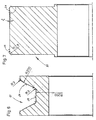
- a profile section of a trapezoidal sheet with an upper flange 1 is shown, which is connected via a web 2 to a lower flange 3.
- This trapezoidal sheet is shown in the state in which it is brought into the last of the roller pairs of a roll former by clamping: the bending edges between the upper flange 1 and the web 2 on the one hand and the bridge and the lower flange 3 on the other are here as radius segments 4 and 5 reproduced.
- the angle represented by them should be, for example, 75 ° relaxed trapezoidal sheet during manufacture and after leaving the last pair of rollers, they are here when passing through bent by the last pair of rolls of the roll former to a higher value, which results from the desired final angle, by summing up the elastic deformation that occurs.
- the radius segments at least as they pass through the last pair of rollers, are molded in more, if only slightly, than is desired in the finished trapezoidal sheet, and in general the radius of curvature of the radius segments is narrowed to a small extent.
- the legs adjoining the radius segments 4, 5 are additionally bent in opposite directions, using such a large radius of curvature that it is still within is the limit of the elastic deformation and thus these additionally formed bends deform when the trapezoidal sheet is relieved and relaxed.
- the effective width of the trapezoidal sheet is hardly shortened by bending the radius segments, since half of the bending is already from the areas 6 and 9 of the straps is recorded and the remaining difference within the width ranges 7 and 8 of the web 2 is reduced, so that its central region is guided with the inclination retained even after relaxation and thus cannot contribute to reducing the effective width of the trapezoidal sheet .
- this reduction in width is kept within relatively narrow limits, it is not necessary to carry out the relaxation stepwise and gradually degrading over several pairs of rollers, as is customary, and thus the usual four to six last pairs of rollers can be achieved by a single pair of rollers designed according to the invention be replaced.
- FIGS. 2 and 3 A practical embodiment of such a pair of rollers for the production of trapezoidal sheets is indicated in FIGS. 2 and 3.
- the shaft of the broken top roller shown at 10. Needle bearings 12, on which rollers 13 run, are arranged on bushings on this shaft 10, and narrower rollers 15 are connected to the shaft 10 via feather keys 14.
- bushings which are penetrated by needle bearings 16 and with which rollers 17 are supported are arranged on the shaft 11 of the lower roller, and rollers 19 are connected to the shaft 11 by keys 18.
- rollers of larger diameters are rotatably connected to the shafts 10, 11 of the top and bottom rollers and, driven, are able to bring about the advance of the trapezoidal sheet, while the rollers 13, 17 of smaller diameter are rotatably held via needle bearings.
- the upper and lower rollers are set against one another, and it is entirely possible to process sheets of different thicknesses, for example from 0.5 to 1.2 mm thick, with the same rollers, the adjustment of the thickness of the sheet being adapted becomes. Furthermore, it is also possible to slightly changing the position to influence the radii of the shaped bending edges.
- FIGS. 4 to 7 In order to show the rounding of the profile, the rollers 13 and 15 of FIGS. 2 and 17 and 19 of FIG. 3 are shown enlarged in FIGS. 4 to 7.
- Fig. 4 it can be clearly seen that the oblique flanks 20 of the roller 13 are each set with a radius of about 3 mm and the flanks 20 themselves are convexly curved practically over their entire length with a large radius of, for example, 200 mm.
- the base enclosed by the flanks 20 is cylindrical in its essentially central width region 21 and falls convexly laterally in the edge regions 22 with a large curvature in the direction of the root of the flanks 20.
- FIG. 5 shows the roller 15 of FIG. 2 on an enlarged scale.
- the foot regions are designed with a radius of, for example, 10 mm, and the lateral surface 23 merges into the flanks on both sides with relatively narrow radii of curvature of less than 3 mm.
- the outer surface itself is concave with a large radius, for example one of 200.8 mm.
- the roller 17 of FIG. 3 shown in FIG. 6 shows that its flanks 24 are convex with a large radius of curvature and merge into lateral surfaces and an annular surface 25 on both sides with a small radius of curvature.
- This ring surface 25 is convex and continuously with a large radius of curvature. In the case of wider ring surfaces, it can also be expedient to distribute the curvature over two side regions and to leave a central region uncurved.
- Fig. 7 shows the roller 19 of Fig. 3 enlarged and shows slightly narrower radii of curvature on both sides at the transition into the flanks.
- the lateral surface formed between them should be inclined inward by at least 5 ° at least in side areas.
- the invention can be applied not only to trapezoidal sheets, but also to other profiled sheets. It is only important here that bending edges or radius segments can be formed which exceed their end angles by the elastic suspension, without further impairment of the profiles produced and the profile being able to emerge directly from this last pair of rollers and requiring no gradual relief which would need additional pairs of roles.
Landscapes
- Engineering & Computer Science (AREA)
- Mechanical Engineering (AREA)
- Bending Of Plates, Rods, And Pipes (AREA)
- Laminated Bodies (AREA)
Claims (6)
- Procèdé pour la fabrication de tôles profilées à partir de bandes ou de plaques de tôle, selon lequel la tôle est introduite successivement entre des galets profilés (galets conformateurs) où elle est formée progressivement, par paliers,entre des galets profilés, apairés, engagés les uns avec les autres, grâce à quoi, à travers des sections de passage de plus en plus réduites jusqu'aux derniers galets apairés, les zones de tôles profilées (arcs 1,3, tronçon de liaison 2), de part et d'autre des arêtes pliées (4,5), sont formées avec la courbure nominale des tôles profilées finies, majorée de l'angle de retour de pliage dû à l'élasticité, et les champs dans leurs zones limites touchant aux arêtes de flexion sont cintrés à contre-sens avec un rayon de courbure, selon lequel la déformation de courbure provoquée se trouve encore en dessous de la déformabilité de la tôle, et selon lequel la sur-flexion des arêtes de pliage, définie par l'angle de retour de pliage élastique, est compensée.
- Procédé selon la revendication 1, caractérisé en ce que chacune des zones de liaison est réalisée vec un rayon de courbure qui compense la moitié du pliage supplémentaire.
- Procédé selon la revendication 1 ou 2, caractérisé en ce que, lorsqu'il y a des champs larges (arcs 1,3, tronçon de liaison 2), seules leurs zones limitrophes (6,9) touchant aux arêtes de flexion (4,5) sont cintrées selon le rayon de courbure, et les autres plages se trouvant entre elles restent non déformées.
- Procédé selon la revendication 1 ou 2, caractérisé en ce que, en particulier lorsqu'il s'agit de sections étroites, les plages suivant les arêtes de pliage limitrophes (4,5) du rayon de courbure se fondent entre elles.
- Dispositif pour la réalisation du procédé selon les revendications de 1 à 4 avec des galets apairés formant les rouleaux, sur l'arbre desquels (10,11), pour chaque section de la tôle profilée à réaliser, un rouleau fixe équipé d'une partie en relief, ainsi qu'un rouleau mobile présentant une gorge sont disposés, et où les parties en relief des rouleaux d'un galet rentrent dans les gorges des rouleaux des autres galets, caractérisé en ce que les flancs obliques (20,24) des gorges présentent une courbure convexe selon un rayon de courbure, et que sur le fond des gorges (21) les courbures de faible rayon prévues pour la mise en forme des arêtes de pliage font suite à des plages limitrophes (22) d'un grand rayon de courbure convexe, qui peuvent être reliées entre elles par une garniture, et que les galets en relief (15,19) ont une courbure concave au moins dans les zones limitrophes de leur garniture (23).
- Rouleaux d'une paire de galets d'après la revendication 5, caractérisés en ce que des gorges larges, ainsi que des galets en relief larges entre les zones limitrophes courbes présentent des garnitures cylindriques, et en ce que les gorges exécutées de manière étroite, ainsi que les galets en relief étroits évoluent ensemble vers une garniture (23,25) courbe de la même manière.
Applications Claiming Priority (2)
| Application Number | Priority Date | Filing Date | Title |
|---|---|---|---|
| DE4132355A DE4132355A1 (de) | 1991-09-27 | 1991-09-27 | Verfahren und anordnung zur herstellung von blechprofilen |
| DE4132355 | 1991-09-27 |
Publications (2)
| Publication Number | Publication Date |
|---|---|
| EP0534281A1 EP0534281A1 (fr) | 1993-03-31 |
| EP0534281B1 true EP0534281B1 (fr) | 1996-10-16 |
Family
ID=6441700
Family Applications (1)
| Application Number | Title | Priority Date | Filing Date |
|---|---|---|---|
| EP92115746A Expired - Lifetime EP0534281B1 (fr) | 1991-09-27 | 1992-09-15 | Méthode et dispositif pour la fabrication des profils en tÔle |
Country Status (3)
| Country | Link |
|---|---|
| EP (1) | EP0534281B1 (fr) |
| AT (1) | ATE144170T1 (fr) |
| DE (2) | DE4132355A1 (fr) |
Families Citing this family (4)
| Publication number | Priority date | Publication date | Assignee | Title |
|---|---|---|---|---|
| RU2118215C1 (ru) * | 1997-08-13 | 1998-08-27 | Общество с ограниченной ответственностью "Металлик" | Профилегибочный стан конструкции м.е.докторова - в.и.пунина |
| DE19938537C1 (de) * | 1999-08-13 | 2001-02-01 | Thyssenkrupp Stahl Ag | Profilieranlage zur Herstellung von Trapezprofilen |
| RU2222402C2 (ru) * | 2002-01-08 | 2004-01-27 | ФГУП "Ульяновский НИАТ" | Способ изготовления симметричных профилей |
| CN108188215A (zh) * | 2017-11-30 | 2018-06-22 | 江苏华电铁塔制造有限公司 | 一种板材折弯模具 |
Family Cites Families (4)
| Publication number | Priority date | Publication date | Assignee | Title |
|---|---|---|---|---|
| US1534299A (en) * | 1921-12-21 | 1925-04-21 | William M Connery | Corrugation-forming die for metal plates |
| GB429753A (en) * | 1933-11-01 | 1935-06-04 | Henry Herbert Crafton | Improvements in apparatus for corrugating sheets |
| GB1001559A (en) * | 1962-04-19 | 1965-08-18 | Scotts Engineering Newport Ltd | Improvements in or relating to corrugating metal sheets |
| GB1359993A (en) * | 1970-09-07 | 1974-07-17 | Ass Eng Ltd | Corrugation-forming machines |
-
1991
- 1991-09-27 DE DE4132355A patent/DE4132355A1/de not_active Withdrawn
-
1992
- 1992-09-15 DE DE59207377T patent/DE59207377D1/de not_active Expired - Fee Related
- 1992-09-15 EP EP92115746A patent/EP0534281B1/fr not_active Expired - Lifetime
- 1992-09-15 AT AT92115746T patent/ATE144170T1/de not_active IP Right Cessation
Also Published As
| Publication number | Publication date |
|---|---|
| EP0534281A1 (fr) | 1993-03-31 |
| DE4132355A1 (de) | 1993-04-01 |
| ATE144170T1 (de) | 1996-11-15 |
| DE59207377D1 (de) | 1996-11-21 |
Similar Documents
| Publication | Publication Date | Title |
|---|---|---|
| DE2752750C2 (de) | Mehrwalzen-Walzgerüst zum Walzen von Flachgut | |
| DE3241995A1 (de) | Verfahren zum korrigieren von gewalztem material | |
| DE3780110T2 (de) | Maschine zum einstellbaren laengswellen von bandmaterial. | |
| DE1917219B2 (de) | Vier-Walzen-Rundbiegemaschine | |
| DE3006526A1 (de) | Verfahren und vorrichtung zum herstellen von elementen mit profiliertem querschnitt aus blech | |
| DE3780453T2 (de) | Walze zum stauchen von flanschen eines walzprofils. | |
| DE2916928A1 (de) | Verfahren und vorrichtung zur herstellung von metallrohren | |
| DE19839614A1 (de) | Biegewälz-Verfahren zur Herstellung von Elektro-Verbund-Röhren mittels Biegewälz-Lager | |
| EP0534281B1 (fr) | Méthode et dispositif pour la fabrication des profils en tÔle | |
| DE2030275A1 (de) | Verfahren und Maschine zum Roll formen von Metallblech | |
| DE2626398C2 (de) | Verfahren und Vorrichtung zum Herstellen eines Flachkäfigs für ein Axial-Wälzlager aus einem Flachkäfigband | |
| EP1491270A1 (fr) | Machine à dresser | |
| DE3872515T2 (de) | Walzstrasse. | |
| DE1801883A1 (de) | Vorrichtung zum Formen der Kanten von Profilstahl mit einem Steg und Flanschen | |
| DE2818909C2 (de) | Richtmaschine für Stangen, Rohre oder dergleichen Werkstücke | |
| EP1197272A2 (fr) | Machine à cintrer à deux rouleaux ainsi que procédé pour cintrer des tôles | |
| DE2413931A1 (de) | Vorrichtung zum woelben oder rollen von blechen | |
| DE3331339A1 (de) | Walzgeruest mit arbeits- und stuetzwalzen sowie zwischen diesen vorgesehenen zwischenwalzen | |
| DE3302333C2 (fr) | ||
| DE60120947T2 (de) | Verfahren und vorrichtung zum biegen von blechstreifen mit zwei einander gegenüberliegenden flanschen | |
| EP2604351A1 (fr) | Laminage des profiles | |
| DE2608410A1 (de) | Einrichtung zum runden von blechstreifen fuer die herstellung von laengsnahtgeschweissten rohren, insbesondere von solchen verhaeltnismaessig grossen durchmessers | |
| DE1452834A1 (de) | Vorrichtung zum Abflachen und Einrollen von Metallstreifen | |
| EP0123120B1 (fr) | Plaque pour une tête de buse d'un système de boîte à buses pour le soufflage de surfaces de forme bombée | |
| DE102023109502B3 (de) | Verfahren zum Richten eines mit Planheitsfehlern behafteten Metallbands |
Legal Events
| Date | Code | Title | Description |
|---|---|---|---|
| PUAI | Public reference made under article 153(3) epc to a published international application that has entered the european phase |
Free format text: ORIGINAL CODE: 0009012 |
|
| 17P | Request for examination filed |
Effective date: 19921006 |
|
| AK | Designated contracting states |
Kind code of ref document: A1 Designated state(s): AT BE CH DE DK ES FR GB GR IE IT LI NL PT SE |
|
| 17Q | First examination report despatched |
Effective date: 19930604 |
|
| RAP1 | Party data changed (applicant data changed or rights of an application transferred) |
Owner name: NAGEL, DIETER |
|
| GRAH | Despatch of communication of intention to grant a patent |
Free format text: ORIGINAL CODE: EPIDOS IGRA |
|
| GRAH | Despatch of communication of intention to grant a patent |
Free format text: ORIGINAL CODE: EPIDOS IGRA |
|
| GRAA | (expected) grant |
Free format text: ORIGINAL CODE: 0009210 |
|
| AK | Designated contracting states |
Kind code of ref document: B1 Designated state(s): AT BE CH DE DK ES FR GB GR IE IT LI NL PT SE |
|
| PG25 | Lapsed in a contracting state [announced via postgrant information from national office to epo] |
Ref country code: NL Free format text: LAPSE BECAUSE OF FAILURE TO SUBMIT A TRANSLATION OF THE DESCRIPTION OR TO PAY THE FEE WITHIN THE PRESCRIBED TIME-LIMIT Effective date: 19961016 Ref country code: GR Free format text: LAPSE BECAUSE OF FAILURE TO SUBMIT A TRANSLATION OF THE DESCRIPTION OR TO PAY THE FEE WITHIN THE PRESCRIBED TIME-LIMIT Effective date: 19961016 Ref country code: GB Effective date: 19961016 Ref country code: FR Effective date: 19961016 Ref country code: ES Free format text: THE PATENT HAS BEEN ANNULLED BY A DECISION OF A NATIONAL AUTHORITY Effective date: 19961016 Ref country code: DK Effective date: 19961016 Ref country code: BE Effective date: 19961016 |
|
| REF | Corresponds to: |
Ref document number: 144170 Country of ref document: AT Date of ref document: 19961115 Kind code of ref document: T |
|
| REF | Corresponds to: |
Ref document number: 59207377 Country of ref document: DE Date of ref document: 19961121 |
|
| REG | Reference to a national code |
Ref country code: IE Ref legal event code: FG4D Free format text: 70242 |
|
| ITF | It: translation for a ep patent filed | ||
| PG25 | Lapsed in a contracting state [announced via postgrant information from national office to epo] |
Ref country code: SE Effective date: 19970116 Ref country code: PT Effective date: 19970116 |
|
| NLV1 | Nl: lapsed or annulled due to failure to fulfill the requirements of art. 29p and 29m of the patents act | ||
| EN | Fr: translation not filed | ||
| EN | Fr: translation not filed |
Free format text: CORRECTIONS |
|
| GBV | Gb: ep patent (uk) treated as always having been void in accordance with gb section 77(7)/1977 [no translation filed] |
Effective date: 19961016 |
|
| PG25 | Lapsed in a contracting state [announced via postgrant information from national office to epo] |
Ref country code: IE Free format text: LAPSE BECAUSE OF NON-PAYMENT OF DUE FEES Effective date: 19970627 |
|
| REG | Reference to a national code |
Ref country code: IE Ref legal event code: FD4D Ref document number: 70242 Country of ref document: IE |
|
| PLBE | No opposition filed within time limit |
Free format text: ORIGINAL CODE: 0009261 |
|
| PG25 | Lapsed in a contracting state [announced via postgrant information from national office to epo] |
Ref country code: AT Free format text: LAPSE BECAUSE OF NON-PAYMENT OF DUE FEES Effective date: 19970915 |
|
| PG25 | Lapsed in a contracting state [announced via postgrant information from national office to epo] |
Ref country code: LI Free format text: LAPSE BECAUSE OF NON-PAYMENT OF DUE FEES Effective date: 19970930 Ref country code: CH Free format text: LAPSE BECAUSE OF NON-PAYMENT OF DUE FEES Effective date: 19970930 |
|
| 26N | No opposition filed | ||
| BERE | Be: lapsed |
Owner name: NAGEL DIETER Effective date: 19970930 |
|
| REG | Reference to a national code |
Ref country code: CH Ref legal event code: PL |
|
| PGFP | Annual fee paid to national office [announced via postgrant information from national office to epo] |
Ref country code: DE Payment date: 19990920 Year of fee payment: 8 |
|
| PG25 | Lapsed in a contracting state [announced via postgrant information from national office to epo] |
Ref country code: DE Free format text: LAPSE BECAUSE OF NON-PAYMENT OF DUE FEES Effective date: 20010601 |
|
| PG25 | Lapsed in a contracting state [announced via postgrant information from national office to epo] |
Ref country code: IT Free format text: LAPSE BECAUSE OF NON-PAYMENT OF DUE FEES;WARNING: LAPSES OF ITALIAN PATENTS WITH EFFECTIVE DATE BEFORE 2007 MAY HAVE OCCURRED AT ANY TIME BEFORE 2007. THE CORRECT EFFECTIVE DATE MAY BE DIFFERENT FROM THE ONE RECORDED. Effective date: 20050915 |