EP0534418B1 - Détecteur à effet Doppler pour déterminer la vitesse d'un véhicule - Google Patents
Détecteur à effet Doppler pour déterminer la vitesse d'un véhicule Download PDFInfo
- Publication number
- EP0534418B1 EP0534418B1 EP92116303A EP92116303A EP0534418B1 EP 0534418 B1 EP0534418 B1 EP 0534418B1 EP 92116303 A EP92116303 A EP 92116303A EP 92116303 A EP92116303 A EP 92116303A EP 0534418 B1 EP0534418 B1 EP 0534418B1
- Authority
- EP
- European Patent Office
- Prior art keywords
- vehicle
- receiver
- wave
- transmitter
- ground
- Prior art date
- Legal status (The legal status is an assumption and is not a legal conclusion. Google has not performed a legal analysis and makes no representation as to the accuracy of the status listed.)
- Expired - Lifetime
Links
Images

Classifications
-
- B—PERFORMING OPERATIONS; TRANSPORTING
- B60—VEHICLES IN GENERAL
- B60T—VEHICLE BRAKE CONTROL SYSTEMS OR PARTS THEREOF; BRAKE CONTROL SYSTEMS OR PARTS THEREOF, IN GENERAL; ARRANGEMENT OF BRAKING ELEMENTS ON VEHICLES IN GENERAL; PORTABLE DEVICES FOR PREVENTING UNWANTED MOVEMENT OF VEHICLES; VEHICLE MODIFICATIONS TO FACILITATE COOLING OF BRAKES
- B60T8/00—Arrangements for adjusting wheel-braking force to meet varying vehicular or ground-surface conditions, e.g. limiting or varying distribution of braking force
- B60T8/17—Using electrical or electronic regulation means to control braking
- B60T8/176—Brake regulation specially adapted to prevent excessive wheel slip during vehicle deceleration, e.g. ABS
- B60T8/1763—Brake regulation specially adapted to prevent excessive wheel slip during vehicle deceleration, e.g. ABS responsive to the coefficient of friction between the wheels and the ground surface
- B60T8/17636—Microprocessor-based systems
-
- B—PERFORMING OPERATIONS; TRANSPORTING
- B60—VEHICLES IN GENERAL
- B60T—VEHICLE BRAKE CONTROL SYSTEMS OR PARTS THEREOF; BRAKE CONTROL SYSTEMS OR PARTS THEREOF, IN GENERAL; ARRANGEMENT OF BRAKING ELEMENTS ON VEHICLES IN GENERAL; PORTABLE DEVICES FOR PREVENTING UNWANTED MOVEMENT OF VEHICLES; VEHICLE MODIFICATIONS TO FACILITATE COOLING OF BRAKES
- B60T8/00—Arrangements for adjusting wheel-braking force to meet varying vehicular or ground-surface conditions, e.g. limiting or varying distribution of braking force
- B60T8/17—Using electrical or electronic regulation means to control braking
- B60T8/173—Eliminating or reducing the effect of unwanted signals, e.g. due to vibrations or electrical noise
-
- B—PERFORMING OPERATIONS; TRANSPORTING
- B60—VEHICLES IN GENERAL
- B60T—VEHICLE BRAKE CONTROL SYSTEMS OR PARTS THEREOF; BRAKE CONTROL SYSTEMS OR PARTS THEREOF, IN GENERAL; ARRANGEMENT OF BRAKING ELEMENTS ON VEHICLES IN GENERAL; PORTABLE DEVICES FOR PREVENTING UNWANTED MOVEMENT OF VEHICLES; VEHICLE MODIFICATIONS TO FACILITATE COOLING OF BRAKES
- B60T8/00—Arrangements for adjusting wheel-braking force to meet varying vehicular or ground-surface conditions, e.g. limiting or varying distribution of braking force
- B60T8/17—Using electrical or electronic regulation means to control braking
- B60T8/176—Brake regulation specially adapted to prevent excessive wheel slip during vehicle deceleration, e.g. ABS
- B60T8/1761—Brake regulation specially adapted to prevent excessive wheel slip during vehicle deceleration, e.g. ABS responsive to wheel or brake dynamics, e.g. wheel slip, wheel acceleration or rate of change of brake fluid pressure
- B60T8/17616—Microprocessor-based systems
Definitions
- the present invention relates to a Doppler-effect type ground-speed sensing apparatus employing a technique for improving the accuracy of ground-speed measurement.
- a conventional ground-speed sensor is disclosed in Japanese Laid-Open Publication No. 63-64861 and includes (a) a transmitter attached to a body of the vehicle and transmitting a detecting wave toward the road surface in a predetermined direction of propagation, (b) a receiver attached to the vehicle body and receiving a portion of the wave which is irregularly reflected by the road surface, and (c) a signal processor which provides an output representative of the ground-speed of the vehicle on the basis of the frequency of the wave transmitted by the transmitter and the frequency of the portion of the wave received by the receiver.
- the optical axis of the known Doppler-effect type ground speed sensor is inclined in one of the opposite running directions of the vehicle, namely, either in the forward running direction or in the reverse or backward running direction of the vehicle.
- document DE-A-3 825 639 discloses an anti-slip system for vehicles, in which a Doppler-effect type sensor is employed which is directed to the ground in an oblique manner.
- a control unit determines from the Doppler frequency and by support of signals derived from further vehicle running condition related sensors the sideward slipping, the wheel slip etc. of the vehicle and feeds corresponding countereffecting signals to a servo system.
- the known ground sensors of this kind are arranged such that the optical axes of both transmitter and receiver are aligned with each other and are parallel to the direction perpendicular to the running directions of the vehicle. These sensors suffer from a large output signal variation when the actual vehicle ground speed is higher than about 100 km/h resulting from a low intensity of the wave received by the receiver at such vehicle speeds and leading to a reduced accuracy of detection of the ground speed of the vehicle.
- the above drawback of the prior art sensors is derived from the fact that the velocity of an air stream between the transmitter and the road surface increases with an increase in the running speed of the vehicle, and that the tendency of scattering of the wave propagating through the air stream increases with an increase in the air flow velocity, whereby the intensity of the wave received by the receiver decreases with the vehicle running speed.
- the receiver of the Doppler-effect ground speed sensor is spaced apart from the transmitter thereof in one of the opposite running directions of the vehicle in which the direction of propagation of the detecting wave from the transmitter toward the road surface is inclined with respect to the downward direction perpendicular to the running directions. That is, if the direction of propagation of the wave is inclined in the forward running direction, the receiver is spaced apart from the transmitter in the forward running direction. If the direction of the wave propagation is inclined in the backward running direction, the receiver is spaced apart from the transmitter in the backward running direction.
- the above arrangement of the Doppler-effect ground-speed sensor according to the invention is advantageous over the prior art sensors in that the irregularly reflected wave received by the receiver is more similar to the wave regularly reflected by the road surface, than in the known sensor.
- the intensity of the irregularly reflected wave received by the receiver of the sensor according to the invention is higher than that received by the receiver of the known sensor.
- the frequency of the wave received by the receiver of the sensor according to the invention more accurately reflects the running speed of the vehicle. That is, the output of the receiver is less likely to be subject to the drawback that the intensity of the received wave decreases with an increase in the vehicle speed. Accordingly, the error in the output of the receiver is reduced, whereby the error or variation in the frequency output of the signal processor is consequently reduced, assuring a reduced amount of error in the ground-speed of the vehicle as detected by the ground-speed sensor.
- the spaced-apart relation of the receiver relative to the transmitter according to the Doppler-effect ground-speed sensor according to the invention is thus substantially free from the influence of the velocity of the air stream between the sensor and the road surface and the influence of the vehicle speed.
- Fig. 1 shows a ground-speed sensor 8 which is used to detect the ground-speed U of the vehicle, namely a running speed of the vehicle relative to the road surface, in the running direction of the vehicle.
- the ground-speed sensor 8 is of a Doppler-effect type which utilizes the Doppler effect of an ultrasonic wave.
- the ground-speed sensor 8 is desirably a Doppler-effect type constructed as shown in Figs. 1 and 2.
- the Doppler-effect ground-speed sensor 8 of Figs. 1 and 2 includes a transmitter 110 which transmits a ultrasonic wave toward the road surface at a predetermined angle of incidence relative to the road surface as indicated in Fig. 2, and a receiver 112 which receives a portion of the ultrasonic wave irregularly reflected by the road surface and generates an output signal in the form of a sine wave representative of a change in the sound pressure of the received wave.
- the transmitter 110 and the receiver 112 are attached to a rear end portion of the underside of the body of the vehicle, such that the receiver 112 is spaced a distance L apart from the transmitter 110 in the backward running direction of the vehicle, as indicated in Fig. 2.
- the optical axes of the transmitter and receiver 110, 112 are inclined in the backward direction of the vehicle, at the same angle ⁇ with respect to the road surface.
- the Doppler-effect ground-speed sensor 8 further includes a signal processor 114 electrically connected to the receiver 112.
- the signal processor 114 receives the output of the receiver 112, and calculates the frequency of the wave received by the receiver 112, from the received output of the receiver 112. Described in detail, the signal processor 114 produces pulses corresponding to those of the peaks of the sine wave represented by the output of the receiver 112, which exceed a threshold level.
- the frequency of the wave received by the receiver 112 is calculated on the basis of the number of the pulses per unit time.
- the signal processor 114 further operates to calculate the ground-speed U of the vehicle, according to the following equation, on the assumption that the angle of incidence of the ultrasonic wave from the transmitter 110 upon the road surface, and the angle of propagation of the reflected wave from the road surface with respect to the road surface are both almost equal to the angle of inclination ⁇ of the optical axes of the transmitter and receiver 110, 112.
- U C ⁇ (Ft - Fr)/ ⁇ (Ft + Fr) ⁇ cos ⁇
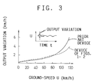
- a known Doppler-effect ground-speed sensor suffers from a considerable increase in the error or variation in the detected ground-speed U, when the actual ground-speed U exceeds about 100km/h, as indicated by solid line in the graph of Fig. 3.
- This increase in the output variation appears to result from a decrease in the intensity of the wave received by the receiver 112 as the actual ground-speed U increases. That is, when the actual ground-speed U is relatively high, the number of the peaks of the sine wave represented by the output of the receiver 112, which peaks exceed the threshold, tends to decrease leading to the reduction in the number of the corresponding pulses from which the frequency Fr of the wave received by the receiver 112 is calculated. Accordingly, the frequency Fr as calculated by the signal processor 114 tends to be lower than the actual frequency of the received wave.
- the receiver 112 is spaced the predetermined distance L apart from the transmitter 110 in the backward running direction of the vehicle, so that the irregularly reflected wave received by the receiver 112 is more similar to the wave regularly reflected by the road surface than in the known sensor.
- the above arrangement of the transmitter and receiver 110, 112 assures a significant decrease in the amount of increase in the output variation when the actual ground-speed U exceeds about 100km/h. As a result, the overall output variation of the sensor over the entire range of the vehicle speed is significantly reduced. In other words, the range of the vehicle ground-speed U that can be accurately detected by the sensor is widened.
- the distance L is 80mm in the illustrated embodiment, this distance L is equal to a distance of forward movement of the vehicle body (and therefore of the receiver 112) at the vehicle speed of about 100km/h while the ultrasonic wave generated by the transmitter 110 is reflected by the road surface and is received by the receiver 112.
- the distance L of 80mm by which the receiver 112 is spaced rearwardly of the transmitter 110 permits the receiver 112 to receive the wave which is irregularly reflected by the road surface, at the same angle as the irregularly reflected wave which is to be received by the receiver of the known ground-speed sensor when the vehicle is stopped.
- the distance L permits the receiver 112 to receive the irregularly reflected wave whose intensity is the same as the irregularly reflected wave received by the receiver of the known sensor when the vehicle is stopped.
- the distance L permits reduction in the amount of increase in the output variation or error of the sensor, when the actual vehicle speed is higher than about 100km/h.
- the Doppler-effect ground-speed sensor shown in Figs. 1 and 2 has a further advantage, when the output of the sensor obtained in a given period is averaged before it is used for example in an anti-lock pressure control operation. That is, the reduced output variation of the ground-speed sensor makes it possible to shorten the time necessary to average the output, and thereby improve the response of the averaged sensor output to the change in the actual ground-speed of the vehicle, whereby the response of an anti-lock brake control apparatus is accordingly enhanced.
- the signal processor 114 is adapted to calculate the ground-speed U of the vehicle on the assumption that the angle of incidence of the transmitted ultrasonic wave upon the road surface and the angle of propagation of the reflected wave from the road surface toward the receiver 112 are almost equal to the inclination angle ⁇ of the optical axes of the transmitter and receiver 110, 112, as described above.
- the angle of incidence of the transmitted wave and the angle of propagation of the reflected wave may be actually detected, so that the ground-speed U is calculated on the basis of the detected angles.
- the receiver 112 is spaced apart from the transmitter 112 in the forward running direction.
Landscapes
- Engineering & Computer Science (AREA)
- Transportation (AREA)
- Mechanical Engineering (AREA)
- Microelectronics & Electronic Packaging (AREA)
- Physics & Mathematics (AREA)
- Fluid Mechanics (AREA)
- Regulating Braking Force (AREA)
- Measurement Of Velocity Or Position Using Acoustic Or Ultrasonic Waves (AREA)
Claims (3)
- Un dispositif de mesure du type à effet Doppler de la vitesse par rapport au sol, agencé dans une caisse de véhicule, comprenant:-
un capteur de la vitesse par rapport au sol qui comprend un émetteur (110) fixé à ladite caisse du véhicule et émettant une onde vers la surface de la route dans une direction de propagation prédéterminée, un récepteur (112) fixé à ladite caisse et recevant une partie de ladite onde qui est réfléchie irrégulièrement par ladite surface de la route, et un processeur de signaux (114) qui produit un signal de sortie représentatif de la vitesse du véhicule par rapport au sol d'après les fréquences de ladite onde émise par ledit émetteur et de ladite partie d'onde reçue par ledit récepteur,
caractérisé en ce que ladite direction de propagation de ladite onde émise par ledit émetteur (110) est inclinée dans la direction de la marche avant du véhicule, et ledit récepteur (112) est espacé dudit émetteur dans ladite direction de la marche avant. - Un dispositif de mesure du type à effet Doppler de la vitesse par rapport au sol, agencé dans une caisse de véhicule, comprenant
un capteur de vitesse par rapport au sol qui comprend un émetteur (110) qui est fixé à ladite caisse du véhicule et qui émet une onde vers la surface de la route dans une direction de propagation prédéterminée, un récepteur (112) fixé à ladite caisse et recevant une partie de ladite onde qui est réfléchie irrégulièrement par la surface de la route, et un processeur de signaux (114) qui fournit un signal de sortie représentatif de la vitesse du véhicule par rapport au sol d'après les fréquences de ladite onde émise par ledit émetteur et de ladite partie de l'onde reçue par ledit récepteur,
caractérisé en ce que ladite direction de propagation de ladite onde émise par ledit émetteur (110) est inclinée dans la direction de la marche arrière du véhicule, et ledit récepteur (112) est espacé dudit l'émetteur dans ladite direction de la marche arrière. - Un dispositif selon la revendication 1 ou la revendication 2,
caractérisé en ce que ledit émetteur (110) émit une onde ultrasonore.
Priority Applications (1)
| Application Number | Priority Date | Filing Date | Title |
|---|---|---|---|
| EP94114390A EP0636526B1 (fr) | 1991-09-24 | 1992-09-23 | Appareil de réglage pour régler un système de frein à antiblocage |
Applications Claiming Priority (4)
| Application Number | Priority Date | Filing Date | Title |
|---|---|---|---|
| JP273317/91 | 1991-09-24 | ||
| JP27331791A JPH0585341A (ja) | 1991-09-24 | 1991-09-24 | アンチロツク制御装置 |
| JP34791791A JPH05157832A (ja) | 1991-12-02 | 1991-12-02 | ドップラ式車速センサ |
| JP347917/91 | 1991-12-02 |
Related Child Applications (1)
| Application Number | Title | Priority Date | Filing Date |
|---|---|---|---|
| EP94114390.1 Division-Into | 1992-09-23 |
Publications (2)
| Publication Number | Publication Date |
|---|---|
| EP0534418A1 EP0534418A1 (fr) | 1993-03-31 |
| EP0534418B1 true EP0534418B1 (fr) | 1996-12-18 |
Family
ID=26550607
Family Applications (2)
| Application Number | Title | Priority Date | Filing Date |
|---|---|---|---|
| EP92116303A Expired - Lifetime EP0534418B1 (fr) | 1991-09-24 | 1992-09-23 | Détecteur à effet Doppler pour déterminer la vitesse d'un véhicule |
| EP94114390A Expired - Lifetime EP0636526B1 (fr) | 1991-09-24 | 1992-09-23 | Appareil de réglage pour régler un système de frein à antiblocage |
Family Applications After (1)
| Application Number | Title | Priority Date | Filing Date |
|---|---|---|---|
| EP94114390A Expired - Lifetime EP0636526B1 (fr) | 1991-09-24 | 1992-09-23 | Appareil de réglage pour régler un système de frein à antiblocage |
Country Status (3)
| Country | Link |
|---|---|
| US (2) | US5334983A (fr) |
| EP (2) | EP0534418B1 (fr) |
| DE (2) | DE69216025T2 (fr) |
Families Citing this family (17)
| Publication number | Priority date | Publication date | Assignee | Title |
|---|---|---|---|---|
| JP2679559B2 (ja) * | 1992-11-05 | 1997-11-19 | トヨタ自動車株式会社 | アンチロック制御装置 |
| JPH06286599A (ja) * | 1993-03-31 | 1994-10-11 | Toyota Motor Corp | 車両用ブレーキ圧制御装置 |
| JP3304575B2 (ja) * | 1993-12-17 | 2002-07-22 | トヨタ自動車株式会社 | アンチロック制御装置 |
| US5547267A (en) * | 1995-02-03 | 1996-08-20 | Kelsey-Hayes Company | Method and system for antilock braking on a deformable surface |
| US5696515A (en) * | 1996-01-31 | 1997-12-09 | Ford Motor Company | System and method for determining absolute vehicle height and ground speed |
| JP3515665B2 (ja) * | 1996-06-19 | 2004-04-05 | 株式会社ホンダエレシス | 車両のアンチロックブレーキ制御装置 |
| US5959572A (en) * | 1997-03-31 | 1999-09-28 | Nissan Motor Co., Ltd. | Vehicle follow-up control apparatus |
| US6438483B1 (en) * | 2001-01-03 | 2002-08-20 | Delphi Technologies, Inc. | System and method for vehicle stability enhancement control during ABS operation |
| US6882920B2 (en) * | 2003-04-29 | 2005-04-19 | Goodrich Corporation | Brake control system |
| EP1851095B1 (fr) * | 2005-02-25 | 2015-03-25 | Freni Brembo S.p.A. | Systemes et procede de commande automatique de freinage pour vehicule |
| JP4798271B2 (ja) | 2009-08-07 | 2011-10-19 | 株式会社デンソー | 車両存在報知装置 |
| GB2523096A (en) * | 2014-02-12 | 2015-08-19 | Jaguar Land Rover Ltd | Apparatus and method for use in a vehicle |
| GB201402387D0 (en) * | 2014-02-12 | 2014-03-26 | Jaguar Land Rover Ltd | Apparatus and method for use in a vehicle |
| GB2523095B (en) * | 2014-02-12 | 2018-01-31 | Jaguar Land Rover Ltd | Apparatus and method for use in a vehicle |
| CN104764897B (zh) * | 2015-02-13 | 2017-09-29 | 盐城工学院 | 汽车测速装置及车速测控方法 |
| CN104655872B (zh) * | 2015-02-13 | 2017-12-19 | 盐城工学院 | 汽车车速测控方法及系统 |
| ITUB20159358A1 (it) * | 2015-12-22 | 2017-06-22 | Faiveley Transport Italia Spa | Procedimento per il controllo e il recupero dell'aderenza delle ruote di un assile controllato di un veicolo ferroviario. |
Family Cites Families (17)
| Publication number | Priority date | Publication date | Assignee | Title |
|---|---|---|---|---|
| US3953083A (en) * | 1974-12-09 | 1976-04-27 | The Bendix Corporation | Duty cycle translator for adaptive braking control circuit |
| GB2034147B (en) * | 1978-09-26 | 1983-02-09 | Nissan Motor | Doppler radar mounting structure for motor vehicles |
| US4432229A (en) * | 1982-06-04 | 1984-02-21 | Rca Corporation | Wheel wear measurement system |
| US4713665A (en) * | 1984-05-14 | 1987-12-15 | Deere & Company | Ground speed sensor |
| US4774667A (en) * | 1985-04-04 | 1988-09-27 | Nippondenso Co., Ltd. | Brake control system for vehicle |
| JP2638785B2 (ja) * | 1986-09-06 | 1997-08-06 | 日産自動車株式会社 | アンチスキツド制御装置 |
| DE3638510C2 (de) * | 1986-11-11 | 1995-04-13 | Teves Gmbh Alfred | Bremsanlage mit Schlupfregelung |
| DE3719821A1 (de) * | 1987-06-13 | 1988-12-29 | Walter Rebholz | Bremssystem fuer ein lenkbares, zwei- oder mehrachsiges, wenigstens hinterachsseitig angetriebenes kraftfahrzeug |
| US4898431A (en) * | 1988-06-15 | 1990-02-06 | Aisin Seiki Kabushiki Kaisha | Brake controlling system |
| DE3825639C2 (de) * | 1988-07-28 | 1995-10-12 | Sepp Gunther | Einrichtung zum Stabilisieren von Kraftfahrzeugen bei Kurvenfahrt |
| JPH02129960A (ja) * | 1988-11-10 | 1990-05-18 | Sony Corp | 半導体メモリ |
| US4986611A (en) * | 1989-02-20 | 1991-01-22 | Nippondenso Co., Ltd. | Anti-lock brake control system for use in motor vehicle |
| JPH03246157A (ja) * | 1990-02-23 | 1991-11-01 | Toyota Motor Corp | アンチスキッド制御装置 |
| JPH03292247A (ja) * | 1990-04-10 | 1991-12-24 | Mazda Motor Corp | 車両の制動制御装置 |
| GB9106110D0 (en) * | 1991-03-22 | 1991-05-08 | Philips Electronic Associated | Doppler radar speed sensor |
| US5243564A (en) * | 1991-08-05 | 1993-09-07 | Toyota Jidosha Kabushiki Kaisha | Doppler-effect vehicle ground-speed detecting apparatus having means for detecting vehicle body inclination |
| JP2679533B2 (ja) * | 1992-05-13 | 1997-11-19 | トヨタ自動車株式会社 | ドップラ式対地車速検出装置 |
-
1992
- 1992-09-10 US US07/942,981 patent/US5334983A/en not_active Expired - Lifetime
- 1992-09-23 DE DE69216025T patent/DE69216025T2/de not_active Expired - Fee Related
- 1992-09-23 DE DE69223525T patent/DE69223525T2/de not_active Expired - Fee Related
- 1992-09-23 EP EP92116303A patent/EP0534418B1/fr not_active Expired - Lifetime
- 1992-09-23 EP EP94114390A patent/EP0636526B1/fr not_active Expired - Lifetime
-
1994
- 1994-03-18 US US08/214,499 patent/US5358318A/en not_active Expired - Lifetime
Also Published As
| Publication number | Publication date |
|---|---|
| EP0636526A1 (fr) | 1995-02-01 |
| DE69223525T2 (de) | 1998-04-23 |
| DE69216025D1 (de) | 1997-01-30 |
| US5358318A (en) | 1994-10-25 |
| DE69223525D1 (de) | 1998-01-22 |
| US5334983A (en) | 1994-08-02 |
| EP0636526B1 (fr) | 1997-12-10 |
| EP0534418A1 (fr) | 1993-03-31 |
| DE69216025T2 (de) | 1997-06-26 |
Similar Documents
| Publication | Publication Date | Title |
|---|---|---|
| EP0534418B1 (fr) | Détecteur à effet Doppler pour déterminer la vitesse d'un véhicule | |
| US5061932A (en) | Road surface sensing system for a vehicle | |
| US6650235B2 (en) | Method and apparatus for recognizing object | |
| CA1200005A (fr) | Dispositif de mesure automatique de la vitesse, de longueur de parcours et des changements de direction d'un vehicule | |
| US5751241A (en) | Method and apparatus for measuring the speed of a moving body | |
| JPH0769421B2 (ja) | 車載用多目的超音波計測装置 | |
| EP0349587A1 (fr) | Systeme de reference de vitesse | |
| JP2004083009A (ja) | 自動二輪車における傾斜検出方法および装置 | |
| JP2905630B2 (ja) | 移動体の性状を測定する装置および移動体の速度測定方法 | |
| JP3563827B2 (ja) | 車載計測装置 | |
| JPH068487Y2 (ja) | 路面検知装置 | |
| JP3171767B2 (ja) | 衝突予知システム | |
| JPH0540173A (ja) | ドツプラ式対地車速検出装置 | |
| JP3440488B2 (ja) | 自動車の操縦支援システムにおける路面状態検出装置 | |
| JP2571991B2 (ja) | 車両のロック防止制動装置用の回路装置 | |
| JP3631550B2 (ja) | 車載用傾斜計測装置および傾斜車速計測装置 | |
| JPH0921870A (ja) | 対地車速検出装置 | |
| JPH05157832A (ja) | ドップラ式車速センサ | |
| JPH02280077A (ja) | 車両姿勢検出装置 | |
| WO2002052298A1 (fr) | Systeme et procede permettant de mesurer des parametres cinematiques d'un pneumatique pendant le fonctionnement d'un vehicule | |
| JP2852844B2 (ja) | 路面反射追従による車両感知方法 | |
| JPH0628595A (ja) | 交通流計測方法 | |
| JP3538890B2 (ja) | 車間距離レーダ装置 | |
| JPH0545459A (ja) | ドツプラ式対地車速検出装置 | |
| JP2580872B2 (ja) | ドップラ型対地車速検出装置 |
Legal Events
| Date | Code | Title | Description |
|---|---|---|---|
| PUAI | Public reference made under article 153(3) epc to a published international application that has entered the european phase |
Free format text: ORIGINAL CODE: 0009012 |
|
| 17P | Request for examination filed |
Effective date: 19920923 |
|
| AK | Designated contracting states |
Kind code of ref document: A1 Designated state(s): DE FR GB |
|
| 17Q | First examination report despatched |
Effective date: 19940513 |
|
| GRAG | Despatch of communication of intention to grant |
Free format text: ORIGINAL CODE: EPIDOS AGRA |
|
| GRAH | Despatch of communication of intention to grant a patent |
Free format text: ORIGINAL CODE: EPIDOS IGRA |
|
| GRAH | Despatch of communication of intention to grant a patent |
Free format text: ORIGINAL CODE: EPIDOS IGRA |
|
| GRAA | (expected) grant |
Free format text: ORIGINAL CODE: 0009210 |
|
| AK | Designated contracting states |
Kind code of ref document: B1 Designated state(s): DE FR GB |
|
| DX | Miscellaneous (deleted) | ||
| ET | Fr: translation filed | ||
| REF | Corresponds to: |
Ref document number: 69216025 Country of ref document: DE Date of ref document: 19970130 |
|
| RIN2 | Information on inventor provided after grant (corrected) |
Free format text: IKEDA, SHINJI * MIZUKOSHI, MASASHI |
|
| PLBE | No opposition filed within time limit |
Free format text: ORIGINAL CODE: 0009261 |
|
| 26N | No opposition filed | ||
| REG | Reference to a national code |
Ref country code: GB Ref legal event code: 746 Effective date: 20010206 |
|
| REG | Reference to a national code |
Ref country code: GB Ref legal event code: IF02 |
|
| REG | Reference to a national code |
Ref country code: FR Ref legal event code: D6 |
|
| PGFP | Annual fee paid to national office [announced via postgrant information from national office to epo] |
Ref country code: FR Payment date: 20080915 Year of fee payment: 17 |
|
| PGFP | Annual fee paid to national office [announced via postgrant information from national office to epo] |
Ref country code: GB Payment date: 20080924 Year of fee payment: 17 |
|
| PGFP | Annual fee paid to national office [announced via postgrant information from national office to epo] |
Ref country code: DE Payment date: 20081002 Year of fee payment: 17 |
|
| GBPC | Gb: european patent ceased through non-payment of renewal fee |
Effective date: 20090923 |
|
| REG | Reference to a national code |
Ref country code: FR Ref legal event code: ST Effective date: 20100531 |
|
| PG25 | Lapsed in a contracting state [announced via postgrant information from national office to epo] |
Ref country code: FR Free format text: LAPSE BECAUSE OF NON-PAYMENT OF DUE FEES Effective date: 20090930 Ref country code: DE Free format text: LAPSE BECAUSE OF NON-PAYMENT OF DUE FEES Effective date: 20100401 |
|
| PG25 | Lapsed in a contracting state [announced via postgrant information from national office to epo] |
Ref country code: GB Free format text: LAPSE BECAUSE OF NON-PAYMENT OF DUE FEES Effective date: 20090923 |