EP0534652A1 - Mäher - Google Patents
MäherInfo
- Publication number
- EP0534652A1 EP0534652A1 EP92308317A EP92308317A EP0534652A1 EP 0534652 A1 EP0534652 A1 EP 0534652A1 EP 92308317 A EP92308317 A EP 92308317A EP 92308317 A EP92308317 A EP 92308317A EP 0534652 A1 EP0534652 A1 EP 0534652A1
- Authority
- EP
- European Patent Office
- Prior art keywords
- mower
- cutting
- tractor
- crop
- discs
- Prior art date
- Legal status (The legal status is an assumption and is not a legal conclusion. Google has not performed a legal analysis and makes no representation as to the accuracy of the status listed.)
- Withdrawn
Links
Images


Classifications
-
- A—HUMAN NECESSITIES
- A01—AGRICULTURE; FORESTRY; ANIMAL HUSBANDRY; HUNTING; TRAPPING; FISHING
- A01D—HARVESTING; MOWING
- A01D34/00—Mowers; Mowing apparatus of harvesters
- A01D34/01—Mowers; Mowing apparatus of harvesters characterised by features relating to the type of cutting apparatus
- A01D34/412—Mowers; Mowing apparatus of harvesters characterised by features relating to the type of cutting apparatus having rotating cutters
- A01D34/63—Mowers; Mowing apparatus of harvesters characterised by features relating to the type of cutting apparatus having rotating cutters having cutters rotating about a vertical axis
- A01D34/64—Mowers; Mowing apparatus of harvesters characterised by features relating to the type of cutting apparatus having rotating cutters having cutters rotating about a vertical axis mounted on a vehicle, e.g. a tractor, or drawn by an animal or a vehicle
- A01D34/66—Mowers; Mowing apparatus of harvesters characterised by features relating to the type of cutting apparatus having rotating cutters having cutters rotating about a vertical axis mounted on a vehicle, e.g. a tractor, or drawn by an animal or a vehicle with two or more cutters
-
- A—HUMAN NECESSITIES
- A01—AGRICULTURE; FORESTRY; ANIMAL HUSBANDRY; HUNTING; TRAPPING; FISHING
- A01D—HARVESTING; MOWING
- A01D34/00—Mowers; Mowing apparatus of harvesters
- A01D34/01—Mowers; Mowing apparatus of harvesters characterised by features relating to the type of cutting apparatus
- A01D34/412—Mowers; Mowing apparatus of harvesters characterised by features relating to the type of cutting apparatus having rotating cutters
- A01D34/63—Mowers; Mowing apparatus of harvesters characterised by features relating to the type of cutting apparatus having rotating cutters having cutters rotating about a vertical axis
- A01D34/76—Driving mechanisms for the cutters
Definitions
- the present invention relates to a mower for harvesting crops.
- One type of conventional tractor-drawn mower comprises a series of cutting discs mounted rotatably to the chassis of the mower in a row at right angles to the direction of movement of the mower as it advances through the crop.
- the discs are usually provided with peripheral cutting elements with the circular cutting paths of such elements on adjacent discs usually being arranged to overlap so that the discs cut a complete swathe of grass between them without leaving a ridge of unmowed grass behind the mower.
- Complicated and expensive synchronisation means or gearboxes have thus been required on such mowers to ensure that overlapping elements do not come into contact with each other as they rotate about their respective axes. Clearly much damage would be caused to the mowing machine should two cutting elements collide with each other.
- the present invention seeks to address these requirements.
- a tractor-drawn mower for use in harvesting a crop
- the mower comprising a frame, at least two rotatable cutting elements for cutting the crop mounted rotatably on the frame, the cutting elements having non-overlapping loci of cutting movement and being arranged on the mover to cut in use overlapping swathes of crop material.
- the mower preferably comprises at least two cutting discs mounted rotatably on the mower frame with the cutting elements being provided at or towards the periphery of the discs.
- the cutting discs are preferably non-synchronised cutting discs with the cutting elements preferably being rotatably mounted on the discs.
- the mower according to the invention is preferably a drum cutter mower with each cutting disc forming part of a drum cutting head and having an associated skid disc mounted rotatably beneath the cutting disc for supporting the mower.
- Typically three such cutting heads are provided in a single row on the mower frame.
- the mower frame preferably comprises a unitary box section arm which rotatably supports each cutting disc.
- the arm is preferably adapted to be suspended from the hitching mount of the tractor and to extend therefrom in use to one side of the tractor so that the mower is not drawn through the crop directly behind the tractor.
- the cutting heads are preferably spaced along the longitudinal axis of the box section arm.
- the mower frame comprises hinge means so that the arm can be swung to an inoperative position where it is drawn directly behind the tractor, and an operative position in which the arm extends laterally of the tractor so that the cutting heads are drawn on an inclined substantially common axis through the crop thereby to cut overlapping swathes of crop material.
- the mower is preferably provided with auxiliary power take-off means so that the mower can draw power from the tractor.
- the mower comprises drive means for rotating the cutting elements in the form of an arrangement of V-belts and pulleys.
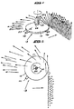
- the tractor-drawn mower 10 shown in the accompanying drawings is suited to cutting crops in harvesting applications. It comprises a frame 12 which rotatably supports three high speed drum cutting heads 13. Each cutting head comprises a cutting disc 14. Cutting elements 16 are provided about the periphery of each disc 14. At the end of the frame, mounting means shown generally at 18, are provided for mounting the mower to the hitching mount of the tractor 19 in a conventional manner. As will be seen in the drawings, the cutting heads 13 are arranged in a single row on the mower frame and are spaced evenly along the longitudinal axis of a unitary box section arm or beam 20 of the frame which is inclined to the direction of movement or advancement of the mower through the vegetation which is to be mowed.
- a jockey wheel 21 is provided which helps to support this end of the frame above the ground.
- auxiliary power take-off means in the form of a power take-off pulley 22 is provided adjacent to the mounting means 18, auxiliary power take-off means in the form of a power take-off pulley 22 is provided by means of which drive means, which are generally indicated at 24, can transmit power from the tractor 19 through to each of the cutting discs 14.
- the drive means 24 in this embodiment of the invention comprise an arrangement of V-belts 25 and pulleys 26. The V-belts and pulleys allow rotational slip of one cutting disc relative to another.
- FIG. 2 the loci of movement of the cutting elements 16 on the periphery of the cutting discs 14 are shown in dotted outline at 28. It will be seen in this view that the loci of movement 28 do not overlap in the direction of the longitudinal axis of the arm 20 of the frame.
- the spaced configuration of the discs means that there is no possibility of the cutting elements 16 colliding with each other and there is consequently no requirement for maintaining synchronisation of the cutting discs, and the necessity of having complicated and expensive gear boxes or other sychronisation means is avoided,
- the mower 10 also has a safety feature which prevents damage to the mower should the inclined arm 20 of the mower come to contact with an obstacle.
- a hinged joint 30 is provided on the frame of the mower and allows the the inclined arm 20 to swing rearwardly behind the tractor should this arm encounter an obstacle. The position of this hinge nevertheless allows the continued transmission of power through to the cutting discs from the power-take off pulley 22.
- the hinge also allows the mower to be swung to an inoperative position where it is drawn directly behind the tractor, and an operative position in which the arm extends laterally of the tractor so that the cutting heads are drawn on an inclined substantially common axis as described above through the crop thereby cutting overlapping swathes of crop material. In this operative position, the arm extends from the hitching mount of the tractor to one side of the tractor so that the mower is not drawn through the crop directly behind the tractor. According, the damage to the crop is minimised..
- FIG. 3 shows a sectional view of a drum cutting head of the mower shown in Figures 1 and 2.
- the high speed cutting discs 14 are each turned by means of a rotating shaft 32.
- the cutting elements 16 are mounted rotatably at or towards the periphery of the cutting discs 14 and can therefore swing freely to clear an obstacle.
- the shaft 32 in supported rotatably in the box section arm 20 by means of bearings 34 and 36.
- a pulley 26 for a V-belt 25 is shown at the top of the shaft and is fast to the shaft 32.
- the lower end of the shaft 32 is provided with an internal bore 40 in which a stub shaft 42 is rotatably supported.
- the stub shaft 42 is held inside the bore 40 by means of a retaining pin 44, or by a grub screw.
- the lower end of the shaft 32 is stepped to define a shoulder at 46. Below the shoulder 46 a square shaft portion 48 is provided which engages in a complementally shaped square recess provided in the centre of the cutting disc 14. Immediately below the square section 48, the shaft is threaded at 50 with the threads in use engaging with a complementally threaded flange nut 52 which can be locked up against the underside of the cutting disc 14 to hold the cutting disc securely in place. Torque is thus transmitted to the associated cutting disc 14 by means of the square shaft section 48.
- the stub shaft 42 depends from the lower end of the rotating shaft 32 and is provided with a centrally disposed circumferential rib or bead 54.
- the stub shaft which is mounted rotatably to the bottom of the rotating shaft 32, carries a skid disc 56 by means of an arrangement of bearings 58 and 60.
- the bearings 58 and 60 are mounted to the shaft as shown in the drawing with the bearing 58 butting up against the circumferential rib 54.
- the bearings 58 and 60 are spaced by means of a spacer 62 and are enclosed by means of a tubular collar 64.
- the skid disc is welded or bolted to the bottom of the collar at 65.
- Each skid disc 56 on the mower 10 prevents its associated cutting disc 14 from coming into contact with the ground and prevents "scalping" by controlling the height at which the cutting elements rotate above the ground.
- the discs 56 support the mower and reduce the load which the mounting means 18 would otherwise be required to carry.
- Each skid disc 56 has an upwardly curving hp 57 which serves to protect the cutting element 16 and prevent the ingress of dirt and debris into the internal workings of the cutting head.
- the skid discs 56 which are barely visible in Figure 1, can rotate independently of the cutting discs 14 and and because of this independent movement, are adapted to negotiate obstacles with relative ease.
- the arrangement of the drum cutting heads 13 provides the mower with an important advantage over conventional "slasher" types of machine.
- the upper surface of the cutting discs tends to support the mown material above the cutting plane of the rotating cutting elements.
- the spinning action of the discs serves to throw the mown material away from the mower and hence minimises damage to the crop.
- a rotating blade would not be able to operate in this manner.
- the shaft 32 has attached to it two radially extending vanes 33 which rotate as the shaft rotates to generate an outwardly directed airflow to assist in clearing the cutting heads of mown material and moving the material backwards away for the mower.
- the vanes 33 also help to prevent vegetation from becoming tangled around the shaft 32.
- the mower according to the invention could of course be used in many applications, but is ideally suited to cutting crops. It is also proposed that the mounting means 18 incorporate appropriate joint means to allow the arm 20 and associated cutting discs 14 to be rotated about the longitudinal axis of the tractor 19 to that the mower can be used to cut crops on steep embankments and the like. As shown in Figure 6, a protective cover 60 and curtain 62 are also provided for the mower, but in the interests of clarity these have not been shown in the other Figures.
- the invention provides a mower of simple design, which dispenses with the need for cutting disc synchronisation means, and yet which is effective to cut a complete swathe of material between adjacent cutting discs.
Landscapes
- Life Sciences & Earth Sciences (AREA)
- Environmental Sciences (AREA)
- Harvester Elements (AREA)
Applications Claiming Priority (2)
| Application Number | Priority Date | Filing Date | Title |
|---|---|---|---|
| ZA917316 | 1991-09-13 | ||
| ZA917316 | 1991-09-13 |
Publications (1)
| Publication Number | Publication Date |
|---|---|
| EP0534652A1 true EP0534652A1 (de) | 1993-03-31 |
Family
ID=25580962
Family Applications (1)
| Application Number | Title | Priority Date | Filing Date |
|---|---|---|---|
| EP92308317A Withdrawn EP0534652A1 (de) | 1991-09-13 | 1992-09-14 | Mäher |
Country Status (4)
| Country | Link |
|---|---|
| US (1) | US5287682A (de) |
| EP (1) | EP0534652A1 (de) |
| CA (1) | CA2078078A1 (de) |
| ZA (1) | ZA926946B (de) |
Cited By (1)
| Publication number | Priority date | Publication date | Assignee | Title |
|---|---|---|---|---|
| KR101663973B1 (ko) * | 2016-05-17 | 2016-10-11 | 제니스테크(주) | 안전성이 향상된 무인 제초기 |
Families Citing this family (3)
| Publication number | Priority date | Publication date | Assignee | Title |
|---|---|---|---|---|
| US20100300055A1 (en) * | 2009-05-28 | 2010-12-02 | Dan Dvorak | Wide-span mowing device |
| US10462964B2 (en) * | 2015-09-16 | 2019-11-05 | Deere & Company | Rear mounted rotating mower assembly |
| JP6877087B2 (ja) * | 2015-11-12 | 2021-05-26 | 株式会社クボタ | 草刈機 |
Citations (7)
| Publication number | Priority date | Publication date | Assignee | Title |
|---|---|---|---|---|
| FR1483721A (fr) * | 1965-04-09 | 1967-06-09 | Appareil faucheur | |
| FR1558853A (de) * | 1967-03-31 | 1969-02-28 | ||
| DE1582350A1 (de) * | 1967-03-31 | 1971-07-15 | Hans Grenzebach | Maehvorrichtung mit rotierenden Schneidwerkzeugen |
| GB1258418A (de) * | 1968-01-04 | 1971-12-30 | ||
| FR2137156A2 (de) * | 1970-11-06 | 1972-12-29 | Gabriel Jean | |
| DE3021500A1 (de) * | 1979-06-08 | 1980-12-11 | Campani Eugenio Cama Snc | Schneidwerk fuer motormaeher zum schneiden insbesondere von futterpflanzen |
| BE1002019A6 (fr) * | 1988-03-23 | 1990-05-22 | Idough Invest Company | Machines pour couper de la vegetation. |
Family Cites Families (4)
| Publication number | Priority date | Publication date | Assignee | Title |
|---|---|---|---|---|
| NL8104178A (nl) * | 1981-09-10 | 1983-04-05 | Lely Nv C Van Der | Flexibele maaikap. |
| DE3410312A1 (de) * | 1984-03-21 | 1985-10-03 | Klöckner-Humboldt-Deutz AG Zweigniederlassung Fahr, 7702 Gottmadingen | Trommelschwader |
| FR2628596B1 (fr) * | 1988-03-15 | 1991-09-06 | Kuhn Sa | Faucheuse a entrainement direct |
| FR2635433B1 (fr) * | 1988-08-18 | 1991-02-01 | Kuhn Sa | Faucheuse a chassis perfectionne |
-
1992
- 1992-09-11 ZA ZA926946A patent/ZA926946B/xx unknown
- 1992-09-11 CA CA002078078A patent/CA2078078A1/en not_active Abandoned
- 1992-09-11 US US07/944,217 patent/US5287682A/en not_active Expired - Fee Related
- 1992-09-14 EP EP92308317A patent/EP0534652A1/de not_active Withdrawn
Patent Citations (7)
| Publication number | Priority date | Publication date | Assignee | Title |
|---|---|---|---|---|
| FR1483721A (fr) * | 1965-04-09 | 1967-06-09 | Appareil faucheur | |
| FR1558853A (de) * | 1967-03-31 | 1969-02-28 | ||
| DE1582350A1 (de) * | 1967-03-31 | 1971-07-15 | Hans Grenzebach | Maehvorrichtung mit rotierenden Schneidwerkzeugen |
| GB1258418A (de) * | 1968-01-04 | 1971-12-30 | ||
| FR2137156A2 (de) * | 1970-11-06 | 1972-12-29 | Gabriel Jean | |
| DE3021500A1 (de) * | 1979-06-08 | 1980-12-11 | Campani Eugenio Cama Snc | Schneidwerk fuer motormaeher zum schneiden insbesondere von futterpflanzen |
| BE1002019A6 (fr) * | 1988-03-23 | 1990-05-22 | Idough Invest Company | Machines pour couper de la vegetation. |
Cited By (1)
| Publication number | Priority date | Publication date | Assignee | Title |
|---|---|---|---|---|
| KR101663973B1 (ko) * | 2016-05-17 | 2016-10-11 | 제니스테크(주) | 안전성이 향상된 무인 제초기 |
Also Published As
| Publication number | Publication date |
|---|---|
| ZA926946B (en) | 1993-03-17 |
| US5287682A (en) | 1994-02-22 |
| CA2078078A1 (en) | 1993-03-14 |
Similar Documents
| Publication | Publication Date | Title |
|---|---|---|
| US10980174B2 (en) | Agricultural mowing device | |
| US10398080B2 (en) | Mulching device for processing plant stubble on a field | |
| JPS639806B2 (de) | ||
| US5809765A (en) | Counterrotation mulching mower and blade assembly | |
| CZ288872B6 (cs) | Sklízecí nástavec zemědělských strojů pro sklízení a odvádění stébelnin, například rostlin kukuřice | |
| US3513648A (en) | Rotary mower disc guards | |
| US3385043A (en) | Rotary mower | |
| US2816410A (en) | Tractor mounted rotary disc cutting assembly | |
| US3716973A (en) | Machines for cutting crops | |
| US2867963A (en) | Rotary disk-type mower cutter mechanism | |
| US4218867A (en) | Haymaking machine | |
| US3862539A (en) | Ground clearing attachment for tractors | |
| US5287682A (en) | Mower | |
| US4478027A (en) | Mower-conditioner | |
| US3115741A (en) | Weed cutter and chopper attachment | |
| US3757502A (en) | Cotton harvester | |
| GB2081565A (en) | Cutting and conditioning crop | |
| US4258535A (en) | Shielding structure for rotary mower | |
| US1945733A (en) | Stalk shredding implement | |
| WO1991011903A1 (en) | Straw treatment apparatus | |
| US20220256771A1 (en) | Arrangement of equipment, working vehicle and method in particular for maintaining green areas, mowing, soil tillage, or harvesting raw or cereal crops | |
| US6827151B1 (en) | Sprig harvester | |
| US4448014A (en) | Apparatus for cutting crop | |
| JP6161973B2 (ja) | 農作業機 | |
| US2703956A (en) | Row dividers for crops |
Legal Events
| Date | Code | Title | Description |
|---|---|---|---|
| PUAI | Public reference made under article 153(3) epc to a published international application that has entered the european phase |
Free format text: ORIGINAL CODE: 0009012 |
|
| AK | Designated contracting states |
Kind code of ref document: A1 Designated state(s): AT BE CH DE DK ES FR GB GR IE IT LI LU MC NL PT SE |
|
| 17P | Request for examination filed |
Effective date: 19930705 |
|
| 17Q | First examination report despatched |
Effective date: 19941004 |
|
| 18D | Application deemed to be withdrawn |
Effective date: 19951109 |