EP0534754A2 - Einziehbares drehbares Werkzeug mit Gleitarretiermechanismus - Google Patents
Einziehbares drehbares Werkzeug mit Gleitarretiermechanismus Download PDFInfo
- Publication number
- EP0534754A2 EP0534754A2 EP92308704A EP92308704A EP0534754A2 EP 0534754 A2 EP0534754 A2 EP 0534754A2 EP 92308704 A EP92308704 A EP 92308704A EP 92308704 A EP92308704 A EP 92308704A EP 0534754 A2 EP0534754 A2 EP 0534754A2
- Authority
- EP
- European Patent Office
- Prior art keywords
- tool
- section
- end portion
- block member
- assembly
- Prior art date
- Legal status (The legal status is an assumption and is not a legal conclusion. Google has not performed a legal analysis and makes no representation as to the accuracy of the status listed.)
- Withdrawn
Links
Images

Classifications
-
- B—PERFORMING OPERATIONS; TRANSPORTING
- B23—MACHINE TOOLS; METAL-WORKING NOT OTHERWISE PROVIDED FOR
- B23B—TURNING; BORING
- B23B31/00—Chucks; Expansion mandrels; Adaptations thereof for remote control
- B23B31/02—Chucks
- B23B31/10—Chucks characterised by the retaining or gripping devices or their immediate operating means
- B23B31/103—Retention by pivotal elements, e.g. catches, pawls
-
- B—PERFORMING OPERATIONS; TRANSPORTING
- B25—HAND TOOLS; PORTABLE POWER-DRIVEN TOOLS; MANIPULATORS
- B25J—MANIPULATORS; CHAMBERS PROVIDED WITH MANIPULATION DEVICES
- B25J15/00—Gripping heads and other end effectors
-
- Y—GENERAL TAGGING OF NEW TECHNOLOGICAL DEVELOPMENTS; GENERAL TAGGING OF CROSS-SECTIONAL TECHNOLOGIES SPANNING OVER SEVERAL SECTIONS OF THE IPC; TECHNICAL SUBJECTS COVERED BY FORMER USPC CROSS-REFERENCE ART COLLECTIONS [XRACs] AND DIGESTS
- Y10—TECHNICAL SUBJECTS COVERED BY FORMER USPC
- Y10T—TECHNICAL SUBJECTS COVERED BY FORMER US CLASSIFICATION
- Y10T279/00—Chucks or sockets
- Y10T279/17—Socket type
- Y10T279/17761—Side detent
- Y10T279/17786—Spring
-
- Y—GENERAL TAGGING OF NEW TECHNOLOGICAL DEVELOPMENTS; GENERAL TAGGING OF CROSS-SECTIONAL TECHNOLOGIES SPANNING OVER SEVERAL SECTIONS OF THE IPC; TECHNICAL SUBJECTS COVERED BY FORMER USPC CROSS-REFERENCE ART COLLECTIONS [XRACs] AND DIGESTS
- Y10—TECHNICAL SUBJECTS COVERED BY FORMER USPC
- Y10T—TECHNICAL SUBJECTS COVERED BY FORMER US CLASSIFICATION
- Y10T279/00—Chucks or sockets
- Y10T279/17—Socket type
- Y10T279/17863—Shouldered-tang holding
-
- Y—GENERAL TAGGING OF NEW TECHNOLOGICAL DEVELOPMENTS; GENERAL TAGGING OF CROSS-SECTIONAL TECHNOLOGIES SPANNING OVER SEVERAL SECTIONS OF THE IPC; TECHNICAL SUBJECTS COVERED BY FORMER USPC CROSS-REFERENCE ART COLLECTIONS [XRACs] AND DIGESTS
- Y10—TECHNICAL SUBJECTS COVERED BY FORMER USPC
- Y10T—TECHNICAL SUBJECTS COVERED BY FORMER US CLASSIFICATION
- Y10T408/00—Cutting by use of rotating axially moving tool
- Y10T408/65—Means to drive tool
-
- Y—GENERAL TAGGING OF NEW TECHNOLOGICAL DEVELOPMENTS; GENERAL TAGGING OF CROSS-SECTIONAL TECHNOLOGIES SPANNING OVER SEVERAL SECTIONS OF THE IPC; TECHNICAL SUBJECTS COVERED BY FORMER USPC CROSS-REFERENCE ART COLLECTIONS [XRACs] AND DIGESTS
- Y10—TECHNICAL SUBJECTS COVERED BY FORMER USPC
- Y10T—TECHNICAL SUBJECTS COVERED BY FORMER US CLASSIFICATION
- Y10T408/00—Cutting by use of rotating axially moving tool
- Y10T408/94—Tool-support
- Y10T408/95—Tool-support with tool-retaining means
-
- Y—GENERAL TAGGING OF NEW TECHNOLOGICAL DEVELOPMENTS; GENERAL TAGGING OF CROSS-SECTIONAL TECHNOLOGIES SPANNING OVER SEVERAL SECTIONS OF THE IPC; TECHNICAL SUBJECTS COVERED BY FORMER USPC CROSS-REFERENCE ART COLLECTIONS [XRACs] AND DIGESTS
- Y10—TECHNICAL SUBJECTS COVERED BY FORMER USPC
- Y10T—TECHNICAL SUBJECTS COVERED BY FORMER US CLASSIFICATION
- Y10T408/00—Cutting by use of rotating axially moving tool
- Y10T408/96—Miscellaneous
Definitions
- This invention relates generally to a motor driven rotatable tool bit and more particularly to a telescoping retractable tool bit assembly driven by a rotary motor used in connection with apparatus for robotically gripping objects.
- Robots are often used to perform these tasks.
- Robots in the past have been utilized to perform both simple and complex tasks in various environments, particularly where human activity is inaccessible, prohibited, or relatively hazardous.
- robotic type apparatus has been put to use in outer space.
- end-effectors are attached to movable robot arms so that objects can be grasped, lifted, manipulated or otherwise operated upon.
- a retractable tool bit assembly comprises at least one rotatable outwardly protruding tool bit holder section; an elongated spring biased tool mounted for axial movement in and out of said holder section and having an inwardly retracted parked position and an outwardly extended use position, said tool further including a backend having a grippable rear end portion; a slider type catch mechanism located adjacent the tool bit holder section and including means for engaging said end portion of said tool when said tool is moved to said parked position and means for releasing said end portion upon rotational movement of said section whereupon said spring biased tool extends fully outward to said use position.
- the present invention provides an improvement in rotatable tool drive apparatus and retractable tool bits.
- the invention also provides a retracted tool bit which remains in a retracted state until required in order to economize the work space into which the tool bit would otherwise protrude.
- the invention also provides a motor driven retractable tool bit assembly used in connection with a robotic gripper assembly.
- a retractable tool bit assembly for a tool such as an allen key and comprising one or more spring loaded nestable or telescoping tubular sections together with a catch mechanism for capturing and holding the tool in its retracted position.
- the smaller inner tubular section includes a threaded cap which engages and holds the tool.
- the catch mechanism consists of a slider type mechanism located adjacent a base section and includes means for engaging the conically shaped inner end portion or head of the tool when the telescoping sections are moved to a retracted or parked position. The catch mechanism is released upon actuation of a rotary tool drive motor coupled to a circular mount and which holds the base section. when released all the telescoping sections and the tool extends fully outward to a use position.
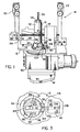
- the gripper assembly 14 comprises an end-effector for a robotic arm, not shown, and includes, among other things, a robotic arm interface plate 16, an electrical drive motor sub-assembly 18 which drives a pair of outwardly extending roller mounted finger elements 20 and 22.
- the finger elements 20 and 22 are respectively secured to two elongated rails 24 and 26 mutually interconnected by a rack and pinion mechanism, not show.
- the two rails 24 and 26 move in mutually opposite directions by means of an elongated Acme screw 28 which is coupled to one of the finger elements and more particularly to element 20, and which is linearly driven through the motor assembly 18 which is shown mounted on the base plate 12.
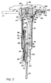
- Figure 1 the tool bit 10 according to this invention is shown in the retracted or parked position, while in Figure 2 it is shown in the extended or use position.
- Figure 2 the preferred embodiment of the invention is shown in detail comprising two mutually telescoping tubular sections 32 and 34, with the outer larger section 32 comprising a base section, and the smaller inner section comprising an extension section which is adapted to hold an elongated tool member 36 in the form of a well known allen key, which is adapted to engage a like type socket, not shown.
- the base section 32 is mounted in and bolted to a rotatable circular mount 38 which extends through an aperture 40 in the gripper base plate 12.
- the mount 38 is fastened to the shaft 42 of a drive motor, not shown, located in the motor sub-assembly 30 ( Figure 1).
- the mount 38 moreover, includes a slot 44 transverse to a central longitudinal axis 46 in which there is located a slider type catch mechanism 48, the details of which will be discussed subsequently.
- the tool 36 and the extension section 34 are spring loaded, i.e. biased, by means of a pair of axially extending compression springs 50 and 52 located within the tubular base section 32 and extension section 34.
- the tool 36 includes a ferrule 54 along its length which abuts a metal cap member 56 so that the compression spring 52 compresses and expands against the cap member while the compression spring 50 compresses and expands against a shoulder 58 formed on the lower half of the extension section 34.
- a threaded end cap 62 is affixed to a threaded outer end portion 64 of the extension section 34.
- both the tool 36 and the inner extension section 34 are retractable against the bias of the spring members 50 and 52.
- Both the ferrule 54 and the extension section 34 additionally include linear keyway grooves 66 and 68 on their outer surfaces which engage key members 70 and 72 on the extension section 64 and the base section 32, respectively, to permit both the extension section 34 and the tool tip 36 to move axially and not spirally when extending and for transmitting torque to the driven element, not shown, engaging the tip 25 of the tool 36.
- extension section 34 is shown in connection with the base section 32, this section can be deleted when desired or a plurality of progressively smaller extension sections 34 can be implemented in combination with the base section 32.
- the tool 36 has a relatively loose fit in the outer extension section 34 and through the axial opening 74 in the end cap 62 in order to allow the tool 36 a certain amount of lateral compliance. This is due to the fact that since the desired application of this invention is in robotics, small amounts of compliance are important, although it is not essential for the operation of the invention.
- the back end of the tool 36 as shown in Figure 2 includes a circular conical or mushroom shaped head 76 which has a flat rear shoulder surface 78 which attaches to a reduced diameter neck portion 80.
- the tool 36 When the tool 36 is compressed inwardly, it first engages the inner wall surface 82 of a tapered hole 83 formed in a spring biased block member 86 which terminates in a circular aperture 84.
- the block member 86 is adapted to slide in and out of the slot 44 against the bias applied by a pair of small compression springs 88 and 90 as shown in Figure 3 located in a pair of small bores 91 and 92 and which operate against the rounded end piece 94.
- a stop member 96 ( Figure 1) which restrains the block 86 from being pushed completely out of the slot 44 by the bias springs 88 and 90.
- the head 76 of the tool 36 is thereafter released upon rotation of the motor driven mount 38 by a spring biased finger mechanism 100 mounted on the gripper plate 12 adjacent the slidable block 86.
- the release mechanism 100 is comprised of a relatively small outwardly protruding finger 102 which is adapted to engage an angulated cam follower type groove 104 formed in the underside of the outer end portion of the block 86 adjacent the finger 102.
- the finger 102 is caught outside of the cam follower groove 104 during retraction of the tool bit 76, it is also slidable in a bore 106, located in the base plate 12, in a direction away from the block 86 while being biased inwardly by means of a small bias spring 108.
- a small cover member 110 keeps the parts in place.
- the tool tip When the tool 36 is no longer needed for use, the tool tip is placed in a shallow cup, not shown, and the tool 36 is compressed axially until all of the telescoping sections are compressed and the head 76 of the tool again engages the catch mechanism 48 in the bottom of the tool bit.
- the catch mechanism 48 engages the tool end 36, keeping the tool 36 fully retracted until it is subsequently released by rotation of the drive motor.
Landscapes
- Engineering & Computer Science (AREA)
- Mechanical Engineering (AREA)
- Robotics (AREA)
- Manipulator (AREA)
Applications Claiming Priority (2)
| Application Number | Priority Date | Filing Date | Title |
|---|---|---|---|
| US765069 | 1991-09-24 | ||
| US07/765,069 US5174694A (en) | 1991-09-24 | 1991-09-24 | Retractable tool bit having slider type catch mechanism |
Publications (2)
| Publication Number | Publication Date |
|---|---|
| EP0534754A2 true EP0534754A2 (de) | 1993-03-31 |
| EP0534754A3 EP0534754A3 (en) | 1993-12-22 |
Family
ID=25072554
Family Applications (1)
| Application Number | Title | Priority Date | Filing Date |
|---|---|---|---|
| EP19920308704 Withdrawn EP0534754A3 (en) | 1991-09-24 | 1992-09-24 | Retractable tool bit having slider type catch mechanism |
Country Status (4)
| Country | Link |
|---|---|
| US (1) | US5174694A (de) |
| EP (1) | EP0534754A3 (de) |
| KR (1) | KR930005706A (de) |
| CA (1) | CA2078297A1 (de) |
Families Citing this family (6)
| Publication number | Priority date | Publication date | Assignee | Title |
|---|---|---|---|---|
| US5451117A (en) * | 1994-01-24 | 1995-09-19 | W. Tregaskiss, Ltd. | Keyed alignment system |
| US5951026A (en) * | 1997-12-12 | 1999-09-14 | Black & Decker Inc. | Removable chuck |
| US6079716A (en) | 1997-12-12 | 2000-06-27 | Black & Decker Inc. | Removable chuck |
| US10336492B2 (en) * | 2015-03-20 | 2019-07-02 | Dyco, Inc. | Sealing jaws for bagging apparatus |
| US10513362B2 (en) * | 2015-03-20 | 2019-12-24 | Dyco, Inc. | Sealing jaws for bagging apparatus |
| US9656394B2 (en) * | 2015-05-21 | 2017-05-23 | GM Global Technology Operations LLC | Robotic system with reconfigurable end-effector assembly |
Family Cites Families (12)
| Publication number | Priority date | Publication date | Assignee | Title |
|---|---|---|---|---|
| US1259603A (en) * | 1917-09-01 | 1918-03-19 | Eugene L Conord | Collapsible tool. |
| US1809273A (en) * | 1924-11-21 | 1931-06-09 | Sinclair Refining Co | Operation of pressure stills |
| US1802053A (en) * | 1928-09-06 | 1931-04-21 | Colonial Tool Company | Broaching equipment |
| US2324852A (en) * | 1943-02-19 | 1943-07-20 | Kopezynski John | Tool |
| US2716393A (en) * | 1949-03-17 | 1955-08-30 | Chicago Pneumatic Tool Co | Chipping hammer tool retainer |
| US2906144A (en) * | 1957-06-18 | 1959-09-29 | Mcmanis Clifford | Means for drilling small bores |
| US3762264A (en) * | 1971-09-29 | 1973-10-02 | Whitney Corp W | Tool holder for punches and the like |
| US3796464A (en) * | 1972-09-27 | 1974-03-12 | Carmet Co | Resilient connection for mining pick and bushing |
| US4520550A (en) * | 1983-05-27 | 1985-06-04 | Automated Robotic Systems, Inc. | Robot tool changer |
| DE3516542A1 (de) * | 1985-05-08 | 1986-11-13 | Robert Bosch Gmbh, 7000 Stuttgart | Werkzeughalter |
| US4662771A (en) * | 1986-04-21 | 1987-05-05 | The Wooster Brush Company | Quick release lock mechanism for telescoping members |
| FR2608085B1 (fr) * | 1986-12-16 | 1991-05-24 | Staubli Sa Ets | Dispositif prehenseur d'outil pour tele-manipulateurs, robots industriels ou ensembles analogues |
-
1991
- 1991-09-24 US US07/765,069 patent/US5174694A/en not_active Expired - Fee Related
-
1992
- 1992-09-15 CA CA002078297A patent/CA2078297A1/en not_active Abandoned
- 1992-09-24 EP EP19920308704 patent/EP0534754A3/en not_active Withdrawn
- 1992-09-24 KR KR1019920017434A patent/KR930005706A/ko not_active Ceased
Also Published As
| Publication number | Publication date |
|---|---|
| US5174694A (en) | 1992-12-29 |
| CA2078297A1 (en) | 1993-03-25 |
| EP0534754A3 (en) | 1993-12-22 |
| KR930005706A (ko) | 1993-04-20 |
Similar Documents
| Publication | Publication Date | Title |
|---|---|---|
| US3973605A (en) | Driving tool barrel assembly | |
| US4441563A (en) | Tool collet and control means | |
| US8308168B2 (en) | Quick change tool bit holder | |
| JP3608659B2 (ja) | 螺子部材締付け装置 | |
| US4536113A (en) | Automatic jaw control for reversible power tool | |
| US3965950A (en) | Fastener driver and fastener holding nosepiece | |
| US9764452B2 (en) | Device and method for fastener element retention and installation | |
| US6561523B1 (en) | Automatic tool-bit holder | |
| US8820431B2 (en) | Power tool with integrated bit retention device | |
| JP6615372B2 (ja) | チャック | |
| US5131706A (en) | Straight line gripper tool and changer | |
| US5184861A (en) | Split rail gripper assembly and tool driver therefor | |
| GB2085400A (en) | Article gripper | |
| US5267766A (en) | Tool gripper | |
| US20110174859A1 (en) | Quick-clamping mechanism for electric hammer | |
| CA2107858A1 (en) | Quick Release Mechanism for Tools Such as Socket Wrenches | |
| US3633640A (en) | Tool having retractable and removable centering sleeve | |
| EP0534754A2 (de) | Einziehbares drehbares Werkzeug mit Gleitarretiermechanismus | |
| US7633246B2 (en) | Portable linear actuator and a method of limiting the maximum force of a motor of such an actuator | |
| US5526721A (en) | Tool having switchable pin-shaped tool elements | |
| JP2010046786A (ja) | ワークの位置決め装置 | |
| US3498624A (en) | Chuck device | |
| US7175184B1 (en) | Collect tool holder and method of making same | |
| US5180259A (en) | Retractable tool bit having latch type catch mechanism | |
| US4476749A (en) | Automatic stud driver |
Legal Events
| Date | Code | Title | Description |
|---|---|---|---|
| PUAI | Public reference made under article 153(3) epc to a published international application that has entered the european phase |
Free format text: ORIGINAL CODE: 0009012 |
|
| 17P | Request for examination filed |
Effective date: 19921009 |
|
| AK | Designated contracting states |
Kind code of ref document: A2 Designated state(s): DE FR GB IT |
|
| PUAL | Search report despatched |
Free format text: ORIGINAL CODE: 0009013 |
|
| AK | Designated contracting states |
Kind code of ref document: A3 Designated state(s): DE FR GB IT |
|
| 18W | Application withdrawn |
Withdrawal date: 19940125 |