EP0534960B1 - Dispositif de prehension - Google Patents
Dispositif de prehension Download PDFInfo
- Publication number
- EP0534960B1 EP0534960B1 EP90912978A EP90912978A EP0534960B1 EP 0534960 B1 EP0534960 B1 EP 0534960B1 EP 90912978 A EP90912978 A EP 90912978A EP 90912978 A EP90912978 A EP 90912978A EP 0534960 B1 EP0534960 B1 EP 0534960B1
- Authority
- EP
- European Patent Office
- Prior art keywords
- grabbing
- bucket
- grabbing device
- arm
- rotation
- Prior art date
- Legal status (The legal status is an assumption and is not a legal conclusion. Google has not performed a legal analysis and makes no representation as to the accuracy of the status listed.)
- Expired - Lifetime
Links
- 230000008878 coupling Effects 0.000 claims abstract description 17
- 238000010168 coupling process Methods 0.000 claims abstract description 17
- 238000005859 coupling reaction Methods 0.000 claims abstract description 17
- 210000005069 ears Anatomy 0.000 claims description 8
- 238000006073 displacement reaction Methods 0.000 claims description 2
- 230000000295 complement effect Effects 0.000 claims 2
- 230000001154 acute effect Effects 0.000 claims 1
- 238000010276 construction Methods 0.000 description 1
- 239000000463 material Substances 0.000 description 1
- 238000000034 method Methods 0.000 description 1
- 238000007789 sealing Methods 0.000 description 1
- 239000002699 waste material Substances 0.000 description 1
Images

Classifications
-
- E—FIXED CONSTRUCTIONS
- E02—HYDRAULIC ENGINEERING; FOUNDATIONS; SOIL SHIFTING
- E02F—DREDGING; SOIL-SHIFTING
- E02F3/00—Dredgers; Soil-shifting machines
- E02F3/04—Dredgers; Soil-shifting machines mechanically-driven
- E02F3/96—Dredgers; Soil-shifting machines mechanically-driven with arrangements for alternate or simultaneous use of different digging elements
- E02F3/962—Mounting of implements directly on tools already attached to the machine
-
- Y—GENERAL TAGGING OF NEW TECHNOLOGICAL DEVELOPMENTS; GENERAL TAGGING OF CROSS-SECTIONAL TECHNOLOGIES SPANNING OVER SEVERAL SECTIONS OF THE IPC; TECHNICAL SUBJECTS COVERED BY FORMER USPC CROSS-REFERENCE ART COLLECTIONS [XRACs] AND DIGESTS
- Y10—TECHNICAL SUBJECTS COVERED BY FORMER USPC
- Y10S—TECHNICAL SUBJECTS COVERED BY FORMER USPC CROSS-REFERENCE ART COLLECTIONS [XRACs] AND DIGESTS
- Y10S37/00—Excavating
- Y10S37/903—Scoop or scraper attachments
-
- Y—GENERAL TAGGING OF NEW TECHNOLOGICAL DEVELOPMENTS; GENERAL TAGGING OF CROSS-SECTIONAL TECHNOLOGIES SPANNING OVER SEVERAL SECTIONS OF THE IPC; TECHNICAL SUBJECTS COVERED BY FORMER USPC CROSS-REFERENCE ART COLLECTIONS [XRACs] AND DIGESTS
- Y10—TECHNICAL SUBJECTS COVERED BY FORMER USPC
- Y10S—TECHNICAL SUBJECTS COVERED BY FORMER USPC CROSS-REFERENCE ART COLLECTIONS [XRACs] AND DIGESTS
- Y10S414/00—Material or article handling
- Y10S414/125—Combined or convertible implements
Definitions
- This invention relates to a grabbing device of the type mentioned in the preamble of the claim.
- SE-A 7900040-0 and 7714027-5 disclose grabbing devices or means directly attached to an excavating bucket.
- Grabbing arms attached to an excavating bucket - symmetrically grabbing as according to the first mentioned publication or grabbing otherwise - make it possible to use the excavator bucket for grabbing and lifting of objects, e.g. pipes, poles and the like.
- the grabbing arms are arranged at the rear side of the bucket, it must be swung into a back position before the grabbing arms can be brought to engage say a pipe lying on the ground, resulting in the grabbing area being concealed to the operator by the bucket.
- the machine arm will be constantly biassed by the weights of the bucket as well as by that of the grabbing device.
- a medium size bucket may have a weight of 1.000 kg or more, it is easily seen that already on idling very heavy weights are handled.
- Another aspect in connection with grabbing devices directly mounted at a bucket is that the bucket and the grabbing device hardly can be expected to have the same life length. As a rule the bucket will be worn out earlier and then the choice would be between keep on repairing the bucket far beyond the normal and economically motivated limit in order to have an at least passable functioning carrier for the grabbing device. The alternative would be to discard or scrap the grabbing device prematurely together with the bucket.
- a bucket equipped with grabbing arms but otherwise arranged in a conventional manner is in the same way as ordinary buckets only movable relatively to the excavator arm about a transversely arranged axis and this fact results in that, in order to grab e.g. a pipe positioned more or less tangentially relatively to the centre of pivot of the excavator, the entire machine must be operated and moved so that the vertical pivot plane of the arm becomes essentially in parallel with the longitudinal direction of said pipe. This, naturally, involves a waste of time and in many instances makes the grabber arms useless and that lifting slings, chains or the like have to be used for changing the position of the object to be lifted.
- SE-A- 8901884-0 discloses a device adapted to be intercoupled between an excavator boom or arm and a bucket or the like tool and such device is so arranged as to allow turning of the bucket around an axis oriented essentially in the length direction of the boom and tilting around an axis in the plane of movement of the boom.
- the bucket may be made work sideways or obliquely and may furthermore be tilted relatively to the boom in order to make possible digging at slopes and the like in spite of the fact that the excavator machine stands in a position, in which conventional bucket connecting means would make digging quite impossible.
- One object of this invention is to bring about a device which besides the utilized functions of known devices increases the grabbing area and positions of the grabbing arms considerably, eliminates the drawback of having to keep attached the operator's view over the working area obstructing bucket and enables a wider field of use by the possibility of combining the device with arbitrary tools at the same time as the device may be disconnected from the excavator on using the excavator for other purposes.
- Another object may be to make it possible to attach a grabbing device directly at the tool holder of the excavator and thereby refraining from utilizing the rotation and tilting arrangement.
- the grabbing device will then be directly carried by the excavator arm via its standardized tool coupling. On attaching and detaching the couplings for the hydraulic system will have to be manually coupled and uncoupled.
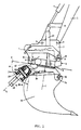
- an essentially conventional rotation arrangement 2 At the outer end of an only partially shown excavator arm 1, there is arranged an essentially conventional rotation arrangement 2 and such arrangement carries an end part 3, by means of a hydraulic cylinder and piston arrangement 4 rotatable relatively to the arm around an axis 5 in a direction transverse to the arm and in parallel with the axis connecting the arm arrangement to the chassis of the excavator.
- a rotating and tilting apparatus as a unit designated 6, is mounted at the end part 3 by means of today conventional quick coupling means.
- This apparatus allows full turning or rotation and sideways tilting of a unit attached or coupled to same apparatus, e.g. an excavating bucket or the like and includes a base plate 7 disconnectably attached to the end part 3 of the arm 1 and equipped with bearings 8 for a yoke part 9, to which a turnplate 10 is attached.
- the turnplate unit has a lower also turnable portion 11, to which is attached a coupling part, the construction and function of which will be described below.
- the yoke part 9 with the turnplate 10 with attached and carried units are - by means of the cylinder and piston units 13 intercoupled between the base plate and the turnplate unit and a not shown pressure medium actuated rotator device - tiltable around an axis A through the bearings 8 and rotatable around the central axis C of the turnplate 10.
- the grabbing device according to the invention is by means of the coupling device 12 arranged at the rotating and tilting apparatus 6 at its side remote from the arm 1.
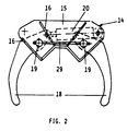
- the grabbing device 14 includes a box like frame, made from two sturdy spaced plates 15 mutually connected by inner and outer flange plates 16. Inside the box like frame there is, between the plates 15 a space 17 for a pair of grabbing arms designated 18.
- the grabbing arms 18 are arranged as double arm levers carried by a bearing pin 19 each, which by reasons given below are axially displaceably carried by the frame.
- the portion of each arm situated on the one side of the bearing pin 19 forms the very grabbing arm whereas the portion on the opposite side forms an abutment for the cylinder and piston device only shown by dash dotted lines, which causes the arms to move into and during the active position and each arm has its own device therefore.
- the cylinder and piston devices 20 are by quick couplings connected to pipes, which via a swivel joint at the rotation and tilting apparatus 6 is connected to the hydraulic system of the machine and its control means.
- So called pilot governed check valves are arranged at the connection for the cylinder and piston devices for safeguarding parallel movements at the grabber arms and furthermore result in a self locking effect so that the grabber arms also in case of a pressure loss remain in reached and by the cylinder and piston devices caused positions.
- the coupling part 12 can as already mentioned be found at the rotatable part 11 of the turnplate and this part has - as can be seen in Fig. 3 - at one end two protruding ears 21 arranged to cooperate with a number of various coupling devices of various types of tools.
- the holed ears have inside edges 22 at a right angle to each other.
- At one end of the grabbing device there are pockets 23 formed by perforated plates 24 welded to the end portions of the flange plates 16. The spaces available for the ears at each pocket are defined inwardly by pins 25 traversing the pocket openings.
- the ears 21 are introduced into the pockets 23 so that the oblique inside edges 22 of the ears engage the pins 25 and align the ears correctly each one in its pocket simultaneously as they serve as additional abutments.
- locking together is achieved by moving the carrying pins 19 so that they traverse each pocket 23 and pass through the hole 24 in each outer plate.
- the movement of the pins is achieved manually, but in an alternative embodiment hydraulic control devices may be engaging the pins 19.
- the pins 19 have radial through bores 28 for a locking rod 29. In the outwardly displaced position the rod runs outside bracing plates 30 but in the inwardly displaced locking position through not shown bores in the same plates. In the embodiment having hydraulic controlled pins the locking may be achieved in another appropriate way.
- Figs. 1 and 2 From especially Figs. 1 and 2 can be seen that the grabbing device is mounted obliquely relatively to the axis C of the turnplate unit and to the plane P, within which the rotatable parts are rotatable.
- the reason behind this is as follows. If a mounting similar to the one shown in the patent referred to, i.e. where the pivot axes of the grabbing arms are parallel with the rear side of the bucket and transfer that idea to a device according to this invention, thus a bucket carried grabbing device connected with the arm 1 over a rotating and tilting apparatus, one will find that in spite of the rotatability blind sectors occur in certain positions of rotation and this is caused by the fact that the maximum achievable angle of movement for the tilting apparatus cannot exceed 40-50°.
- the grabbing device according to this invention is obliquely arranged relatively to the rotational axis C or plane P and more in detail so that radial planes through the mutually parallel axes of the grabbing arms lie in about 40-50° angle relatively to the plane P of rotation around the axis C.
- Fig. 1 shows in dash lines how the pivot plane S of the grabbing arms forms an angle relatively to the plane P of the rotation apparatus.
- the possible angle of tilting V i.e. the largest angle the rotational plane of the grabbing device may be displaced into by means of the cylinder and piston devices 13, together with the oblique angle of the gr-abbing device relatively to the plane P of rotation, is 90°.
- the dead or blind sectors are eliminated by the arrangement described and the grabbing device can function independent of the rotational position.
- attachment means or connectors there are at the rotation and tilting apparatus another set of attachment means or connectors. These include hooks 31 intended to co-operate with transverse abutment studs 32 at a bucket or the like 33 and a locking wedge means 34 movable by means of a cylinder and piston arrangement, the wedge means being arranged to as a wedge engage a cooperating fitting on the upper side of the bucket for lockingly secure same.
- hooks 31 intended to co-operate with transverse abutment studs 32 at a bucket or the like 33
- a locking wedge means 34 movable by means of a cylinder and piston arrangement, the wedge means being arranged to as a wedge engage a cooperating fitting on the upper side of the bucket for lockingly secure same.
- the grabbing device only is to be used, it is normally advantageous to disconnect the bucket and put it aside as otherwise also the weight of the bucket, up to and even exceeding 1.000 kg, reduces the pay-load handable by the grabbing device. For the same reason, it is possible if only excavating is at hand, to disconnect the bucket and the grabbing device and disconnect the latter from the rotation and tilting apparatus and connect the bucket directly to same.
- the grabbing device is carried by the rotation and tilting apparatus makes it very movable and it is possible to grab in all directions without problems and also handle and position the load carried.
- the latter is of importance especially in pipe laying work as you may put the pipes down into the dug pit aligned and in correct position and further move the pipes towards already put down pipes in order to achieve an interconnecting of same.
- Conventional pulling together normally necessary tools are, thus, superfluous.
Landscapes
- Engineering & Computer Science (AREA)
- Mechanical Engineering (AREA)
- Mining & Mineral Resources (AREA)
- Civil Engineering (AREA)
- General Engineering & Computer Science (AREA)
- Structural Engineering (AREA)
- Earth Drilling (AREA)
- Load-Engaging Elements For Cranes (AREA)
- Shovels (AREA)
Abstract
Claims (5)
- Dispositif de préhension, de préférence porté par un bras ou une potence (1) d'une pelleteuse ou d'un engin porteur d'outil analogue, qui peut également porter un godet ou un outil analogue (33), dans lequel l'entité de préhension (14) et le godet (33) sont destinés à fonctionner chacun séparément, et dans lequel le dispositif de préhension (14) est constitué d'une entité séparée propre à être fixée à un organe de rotation et d'inclinaison (6) disposé sur le bras, ou potence (1), et autorisant un déplacement et une rotation, par rapport au bras, d'outils et de dispositifs (33) portés par l'organe (6), ledit organe (6) comprenant des moyens de connexion (31, 34) ménagés pour coopérer, par complémentarité, avec des moyens de connexion connus (32) d'un godet ou d'un outil analogue (33), caractérisé en ce que le dispositif de préhension (14) possède ses propres moyens de couplage (23), ménagés pour coopérer avec des moyens de couplage complémentaires (21) ménagés sur l'organe de rotation inclinable (6) à distance des moyens de connexion (31, 34) ménagés pour coopérer avec les moyens de connexion (32) d'un godet ou analogue (33), autorisant l'emploi du dispositif de préhension (14) indépendamment du fait que le godet (33) est connecté ou non, et en ce que le dispositif de préhension (14) est situé de telle sorte que le plan (S) du mouvement pivotant des bras de préhension (18) forme un angle aigu avec l'axe central (C) et le plan (P) de l'organe de rotation.
- Dispositif selon la revendication 1, dans lequel l'angle (α) entre le plan du mouvement pivotant des bras de préhension (18) et la rotation, ou plan rotatif (P), de l'organe de rotation (6) atteint une valeur correspondant, sensiblement, à la différence entre 90° et l'angle oblique que peut atteindre l'organe d'inclinaison (6).
- Dispositif selon la revendication 2, dans lequel le dispositif de préhension (14) comprend une entité en forme de boîte avec une chambre (17) de réception d'une paire de bras de préhension (18) dans leur position de repos qui comprend, également, une paire de modules à cylindres et pistons (20), chacun couplé à un bras (18), et dans lequel les bras de préhension (18) forment deux leviers pivotants portés, chacun, par un axe de pivot (19) à son tour porté dans des trous ménagés à travers les parois (15) de l'entité en forme de boîte.
- Dispositif selon la revendication 3, dans lequel l'entité en forme de boîte présente des poches (23), adjacentes aux axes de pivotement (19), ouvertes vers l'extérieur et formant des moyens de couplage pour recevoir des languettes de formes complémentaires (21) constituant des moyens de couplage de l'organe de rotation et d'inclinaison (6), pour bloquer les même languettes (21) au moyen des extrémités des axes de pivotement (19) prévus pour traverser lesdites poches (23) en étant déplacés axialement et en étant logés dans des cavités de la boîte.
- Dispositif selon la revendication 3, dans lequel des valves dites à clapet anti-retour piloté sont connectées avec le module à cylindre et piston (20) inclinant les bras de préhension (18), pour assurer un mouvement parallèle des deux bras (18) et les maintenir verrouillés dans la position atteinte en cas de perte de fluide sous pression.
Applications Claiming Priority (3)
| Application Number | Priority Date | Filing Date | Title |
|---|---|---|---|
| SE8902796 | 1989-08-22 | ||
| SE8902796A SE464645C (sv) | 1989-08-22 | 1989-08-22 | Gripanordning |
| PCT/SE1990/000532 WO1991002852A1 (fr) | 1989-08-22 | 1990-08-16 | Dispositif de prehension |
Publications (2)
| Publication Number | Publication Date |
|---|---|
| EP0534960A1 EP0534960A1 (fr) | 1993-04-07 |
| EP0534960B1 true EP0534960B1 (fr) | 1996-04-17 |
Family
ID=20376713
Family Applications (1)
| Application Number | Title | Priority Date | Filing Date |
|---|---|---|---|
| EP90912978A Expired - Lifetime EP0534960B1 (fr) | 1989-08-22 | 1990-08-16 | Dispositif de prehension |
Country Status (6)
| Country | Link |
|---|---|
| US (1) | US5237762A (fr) |
| EP (1) | EP0534960B1 (fr) |
| DE (1) | DE69026629T2 (fr) |
| ES (1) | ES2085913T3 (fr) |
| SE (1) | SE464645C (fr) |
| WO (1) | WO1991002852A1 (fr) |
Families Citing this family (15)
| Publication number | Priority date | Publication date | Assignee | Title |
|---|---|---|---|---|
| SE9102566L (sv) * | 1991-09-06 | 1992-09-07 | Sonerud John Teodor | Anordning foer snabbkoppling av ett redskap till en graevmaskin med samtidig anslutning till ett drivsystem |
| SE506016C2 (sv) * | 1993-12-16 | 1997-11-03 | Bernt Wedberg | Snabbfäste för arbetsmaskiner |
| US5575093A (en) * | 1995-04-20 | 1996-11-19 | Rockland, Inc. | Coupler assembly |
| US5865492A (en) * | 1997-01-07 | 1999-02-02 | Wec Company | Hydraulic grapple assembly with side rotation mechanism |
| US6139212A (en) * | 1998-02-11 | 2000-10-31 | Rockland Manufacturing Co. | Coupler for excavating machines and the like having fixed and moveable jaws |
| US20060248754A1 (en) * | 2005-05-09 | 2006-11-09 | Martin Gerald G | Excavator stump shearing device |
| GB2435653C (en) * | 2006-03-01 | 2019-03-20 | John Thomas Gareth | Excavator |
| GB2435654B (en) * | 2006-03-01 | 2010-12-08 | Gareth John Thomas | Attachment for excavator |
| US7984575B2 (en) * | 2007-07-05 | 2011-07-26 | Caterpillar Inc. | Quick coupler assembly |
| US8974137B2 (en) | 2011-12-22 | 2015-03-10 | Caterpillar Inc. | Quick coupler |
| US8869437B2 (en) | 2012-05-30 | 2014-10-28 | Caterpillar Inc. | Quick coupler |
| US8684623B2 (en) | 2012-05-30 | 2014-04-01 | Caterpillar Inc. | Tool coupler having anti-release mechanism |
| US9217235B2 (en) | 2012-05-30 | 2015-12-22 | Caterpillar Inc. | Tool coupler system having multiple pressure sources |
| US9228314B2 (en) | 2013-05-08 | 2016-01-05 | Caterpillar Inc. | Quick coupler hydraulic control system |
| AT516867A1 (de) * | 2015-02-26 | 2016-09-15 | Perwein Baumaschinen-Systeme Gmbh | Aufhängung für Kupplungsvorrichtung mit integrierter Schwenkvorrichtung |
Family Cites Families (10)
| Publication number | Priority date | Publication date | Assignee | Title |
|---|---|---|---|---|
| SE416338B (sv) * | 1975-12-04 | 1980-12-15 | Lundberg Hymans Ab | Sett och anordning for resning av stolpar och liknande langstreckta foremal |
| SE411467B (sv) * | 1977-12-09 | 1979-12-27 | Soneruds Maskin Ab | Anordning for grevning av stolphal och resning av stpolpar |
| SE428138B (sv) * | 1979-01-03 | 1983-06-06 | Soneruds Maskin Ab | Grevskopa med gripanordning |
| US4355476A (en) * | 1979-01-03 | 1982-10-26 | Soneruds Maskin Aktiebolag | Bucket assembly |
| US4268217A (en) * | 1979-02-23 | 1981-05-19 | Perreault Arthur W | Load carrying apparatus |
| US4297799A (en) * | 1980-02-25 | 1981-11-03 | Soneruds Maskin Aktiebolag | Apparatus for digging post holes and erecting posts |
| SE439173B (sv) * | 1980-10-02 | 1985-06-03 | Pejo Sekerhetsdetaljer Ab | Anordning for gripning och resning av stolpar monterad pa en grevskopa |
| US4515522A (en) * | 1983-01-19 | 1985-05-07 | Sonerud John Teodor | Pipelaying appliance |
| IN172013B (fr) * | 1985-11-04 | 1993-03-13 | Holmdahl Ulf Goeran | |
| US4958981A (en) * | 1988-12-20 | 1990-09-25 | Masatoshi Uchihashi | Attachment connector assembly for hydraulic shovel type excavator |
-
1989
- 1989-08-22 SE SE8902796A patent/SE464645C/sv not_active IP Right Cessation
-
1990
- 1990-08-16 ES ES90912978T patent/ES2085913T3/es not_active Expired - Lifetime
- 1990-08-16 DE DE69026629T patent/DE69026629T2/de not_active Expired - Fee Related
- 1990-08-16 US US07/834,224 patent/US5237762A/en not_active Expired - Fee Related
- 1990-08-16 EP EP90912978A patent/EP0534960B1/fr not_active Expired - Lifetime
- 1990-08-16 WO PCT/SE1990/000532 patent/WO1991002852A1/fr not_active Ceased
Also Published As
| Publication number | Publication date |
|---|---|
| ES2085913T3 (es) | 1996-06-16 |
| SE8902796D0 (sv) | 1989-08-22 |
| DE69026629D1 (de) | 1996-05-23 |
| EP0534960A1 (fr) | 1993-04-07 |
| WO1991002852A1 (fr) | 1991-03-07 |
| SE464645B (sv) | 1991-05-27 |
| SE8902796L (sv) | 1991-02-23 |
| SE464645C (sv) | 1993-02-08 |
| US5237762A (en) | 1993-08-24 |
| DE69026629T2 (de) | 1996-11-21 |
Similar Documents
| Publication | Publication Date | Title |
|---|---|---|
| EP0534960B1 (fr) | Dispositif de prehension | |
| US5423625A (en) | Boom/arm coupler for excavator | |
| US5546683A (en) | Bucket attachment device with remote controlled retractable pins | |
| CA1329627C (fr) | Attelage hydraulique a desaccouplement rapide pour materiel de chantier | |
| EP2367984B1 (fr) | Dispositif de couplage pour outil d'engin de terrassement | |
| US5813822A (en) | Bucket and thumb combination as a quick decoupling attachment | |
| US5219265A (en) | Grapple assembly | |
| US6379075B1 (en) | Quick coupler apparatus | |
| CA1138828A (fr) | Interconnection demontable | |
| US6422805B1 (en) | Quick coupler for bucket excavators | |
| EP0812963A2 (fr) | Godet polyvalent | |
| EP2230435A1 (fr) | Coupleur fluide extensible | |
| US4804309A (en) | Gripping device for boom-mounted work tool | |
| US6158950A (en) | Excavator coupling | |
| JPS61137927A (ja) | 掘削機ア−ムへの取着用迅速解放ヒツチ | |
| US4948328A (en) | Quick attach bucket system for backhoes and the like | |
| JPH11315551A (ja) | 建設機械における迅速接続装置 | |
| US6139212A (en) | Coupler for excavating machines and the like having fixed and moveable jaws | |
| US6163988A (en) | Assembly connectable to an operating arm of a machine for performing work functions | |
| US6725584B2 (en) | Quick connect/disconnect system for an arm of excavator or other machine | |
| US5111888A (en) | Hammer-swinging mechanism | |
| WO2004016863A1 (fr) | Systeme d'accouplement | |
| EP0907804B1 (fr) | Dispositif de mise en rotation | |
| WO2000061485A1 (fr) | Grappin avec fixation universelle | |
| WO2000004242A1 (fr) | Ensemble de couplage pour materiel d'excavation |
Legal Events
| Date | Code | Title | Description |
|---|---|---|---|
| PUAI | Public reference made under article 153(3) epc to a published international application that has entered the european phase |
Free format text: ORIGINAL CODE: 0009012 |
|
| 17P | Request for examination filed |
Effective date: 19920206 |
|
| AK | Designated contracting states |
Kind code of ref document: A1 Designated state(s): BE CH DE ES FR GB IT LI NL SE |
|
| 17Q | First examination report despatched |
Effective date: 19940414 |
|
| ITF | It: translation for a ep patent filed | ||
| GRAA | (expected) grant |
Free format text: ORIGINAL CODE: 0009210 |
|
| AK | Designated contracting states |
Kind code of ref document: B1 Designated state(s): BE CH DE ES FR GB IT LI NL SE |
|
| REG | Reference to a national code |
Ref country code: CH Ref legal event code: NV Representative=s name: BOVARD AG PATENTANWAELTE |
|
| REF | Corresponds to: |
Ref document number: 69026629 Country of ref document: DE Date of ref document: 19960523 |
|
| REG | Reference to a national code |
Ref country code: ES Ref legal event code: FG2A Ref document number: 2085913 Country of ref document: ES Kind code of ref document: T3 |
|
| ET | Fr: translation filed | ||
| PLBE | No opposition filed within time limit |
Free format text: ORIGINAL CODE: 0009261 |
|
| STAA | Information on the status of an ep patent application or granted ep patent |
Free format text: STATUS: NO OPPOSITION FILED WITHIN TIME LIMIT |
|
| 26N | No opposition filed | ||
| REG | Reference to a national code |
Ref country code: GB Ref legal event code: IF02 |
|
| PGFP | Annual fee paid to national office [announced via postgrant information from national office to epo] |
Ref country code: SE Payment date: 20030806 Year of fee payment: 14 |
|
| PGFP | Annual fee paid to national office [announced via postgrant information from national office to epo] |
Ref country code: FR Payment date: 20030808 Year of fee payment: 14 |
|
| PGFP | Annual fee paid to national office [announced via postgrant information from national office to epo] |
Ref country code: GB Payment date: 20030813 Year of fee payment: 14 |
|
| PGFP | Annual fee paid to national office [announced via postgrant information from national office to epo] |
Ref country code: CH Payment date: 20030818 Year of fee payment: 14 |
|
| PGFP | Annual fee paid to national office [announced via postgrant information from national office to epo] |
Ref country code: DE Payment date: 20030828 Year of fee payment: 14 |
|
| PGFP | Annual fee paid to national office [announced via postgrant information from national office to epo] |
Ref country code: NL Payment date: 20030831 Year of fee payment: 14 |
|
| PGFP | Annual fee paid to national office [announced via postgrant information from national office to epo] |
Ref country code: ES Payment date: 20030926 Year of fee payment: 14 |
|
| PGFP | Annual fee paid to national office [announced via postgrant information from national office to epo] |
Ref country code: BE Payment date: 20031009 Year of fee payment: 14 |
|
| PG25 | Lapsed in a contracting state [announced via postgrant information from national office to epo] |
Ref country code: GB Free format text: LAPSE BECAUSE OF NON-PAYMENT OF DUE FEES Effective date: 20040816 |
|
| PG25 | Lapsed in a contracting state [announced via postgrant information from national office to epo] |
Ref country code: SE Free format text: LAPSE BECAUSE OF NON-PAYMENT OF DUE FEES Effective date: 20040817 Ref country code: ES Free format text: LAPSE BECAUSE OF NON-PAYMENT OF DUE FEES Effective date: 20040817 |
|
| PG25 | Lapsed in a contracting state [announced via postgrant information from national office to epo] |
Ref country code: LI Free format text: LAPSE BECAUSE OF NON-PAYMENT OF DUE FEES Effective date: 20040831 Ref country code: CH Free format text: LAPSE BECAUSE OF NON-PAYMENT OF DUE FEES Effective date: 20040831 Ref country code: BE Free format text: LAPSE BECAUSE OF NON-PAYMENT OF DUE FEES Effective date: 20040831 |
|
| BERE | Be: lapsed |
Owner name: *SANDBERG STIG Effective date: 20040831 |
|
| PG25 | Lapsed in a contracting state [announced via postgrant information from national office to epo] |
Ref country code: NL Free format text: LAPSE BECAUSE OF NON-PAYMENT OF DUE FEES Effective date: 20050301 Ref country code: DE Free format text: LAPSE BECAUSE OF NON-PAYMENT OF DUE FEES Effective date: 20050301 |
|
| EUG | Se: european patent has lapsed | ||
| GBPC | Gb: european patent ceased through non-payment of renewal fee |
Effective date: 20040816 |
|
| REG | Reference to a national code |
Ref country code: CH Ref legal event code: PL |
|
| PG25 | Lapsed in a contracting state [announced via postgrant information from national office to epo] |
Ref country code: FR Free format text: LAPSE BECAUSE OF NON-PAYMENT OF DUE FEES Effective date: 20050429 |
|
| NLV4 | Nl: lapsed or anulled due to non-payment of the annual fee |
Effective date: 20050301 |
|
| REG | Reference to a national code |
Ref country code: FR Ref legal event code: ST |
|
| PG25 | Lapsed in a contracting state [announced via postgrant information from national office to epo] |
Ref country code: IT Free format text: LAPSE BECAUSE OF NON-PAYMENT OF DUE FEES Effective date: 20050816 |
|
| REG | Reference to a national code |
Ref country code: ES Ref legal event code: FD2A Effective date: 20040817 |
|
| BERE | Be: lapsed |
Owner name: *SANDBERG STIG Effective date: 20040831 |