EP0535295A1 - Einrichtung zur Verarbeitung von hochviskosem Kautschuk oder thermoplastischem Kunststoff - Google Patents
Einrichtung zur Verarbeitung von hochviskosem Kautschuk oder thermoplastischem Kunststoff Download PDFInfo
- Publication number
- EP0535295A1 EP0535295A1 EP92104280A EP92104280A EP0535295A1 EP 0535295 A1 EP0535295 A1 EP 0535295A1 EP 92104280 A EP92104280 A EP 92104280A EP 92104280 A EP92104280 A EP 92104280A EP 0535295 A1 EP0535295 A1 EP 0535295A1
- Authority
- EP
- European Patent Office
- Prior art keywords
- shaft
- housing
- diameter
- sides
- conveying members
- Prior art date
- Legal status (The legal status is an assumption and is not a legal conclusion. Google has not performed a legal analysis and makes no representation as to the accuracy of the status listed.)
- Granted
Links
Images


Classifications
-
- F—MECHANICAL ENGINEERING; LIGHTING; HEATING; WEAPONS; BLASTING
- F04—POSITIVE - DISPLACEMENT MACHINES FOR LIQUIDS; PUMPS FOR LIQUIDS OR ELASTIC FLUIDS
- F04C—ROTARY-PISTON, OR OSCILLATING-PISTON, POSITIVE-DISPLACEMENT MACHINES FOR LIQUIDS; ROTARY-PISTON, OR OSCILLATING-PISTON, POSITIVE-DISPLACEMENT PUMPS
- F04C2/00—Rotary-piston machines or pumps
- F04C2/08—Rotary-piston machines or pumps of intermeshing-engagement type, i.e. with engagement of co-operating members similar to that of toothed gearing
- F04C2/082—Details specially related to intermeshing engagement type machines or pumps
- F04C2/084—Toothed wheels
-
- B—PERFORMING OPERATIONS; TRANSPORTING
- B29—WORKING OF PLASTICS; WORKING OF SUBSTANCES IN A PLASTIC STATE IN GENERAL
- B29B—PREPARATION OR PRETREATMENT OF THE MATERIAL TO BE SHAPED; MAKING GRANULES OR PREFORMS; RECOVERY OF PLASTICS OR OTHER CONSTITUENTS OF WASTE MATERIAL CONTAINING PLASTICS
- B29B7/00—Mixing; Kneading
- B29B7/30—Mixing; Kneading continuous, with mechanical mixing or kneading devices
- B29B7/58—Component parts, details or accessories; Auxiliary operations
-
- B—PERFORMING OPERATIONS; TRANSPORTING
- B29—WORKING OF PLASTICS; WORKING OF SUBSTANCES IN A PLASTIC STATE IN GENERAL
- B29B—PREPARATION OR PRETREATMENT OF THE MATERIAL TO BE SHAPED; MAKING GRANULES OR PREFORMS; RECOVERY OF PLASTICS OR OTHER CONSTITUENTS OF WASTE MATERIAL CONTAINING PLASTICS
- B29B7/00—Mixing; Kneading
- B29B7/30—Mixing; Kneading continuous, with mechanical mixing or kneading devices
- B29B7/58—Component parts, details or accessories; Auxiliary operations
- B29B7/60—Component parts, details or accessories; Auxiliary operations for feeding, e.g. end guides for the incoming material
-
- B—PERFORMING OPERATIONS; TRANSPORTING
- B29—WORKING OF PLASTICS; WORKING OF SUBSTANCES IN A PLASTIC STATE IN GENERAL
- B29C—SHAPING OR JOINING OF PLASTICS; SHAPING OF MATERIAL IN A PLASTIC STATE, NOT OTHERWISE PROVIDED FOR; AFTER-TREATMENT OF THE SHAPED PRODUCTS, e.g. REPAIRING
- B29C48/00—Extrusion moulding, i.e. expressing the moulding material through a die or nozzle which imparts the desired form; Apparatus therefor
- B29C48/25—Component parts, details or accessories; Auxiliary operations
- B29C48/36—Means for plasticising or homogenising the moulding material or forcing it through the nozzle or die
- B29C48/465—Means for plasticising or homogenising the moulding material or forcing it through the nozzle or die using rollers
-
- F—MECHANICAL ENGINEERING; LIGHTING; HEATING; WEAPONS; BLASTING
- F04—POSITIVE - DISPLACEMENT MACHINES FOR LIQUIDS; PUMPS FOR LIQUIDS OR ELASTIC FLUIDS
- F04C—ROTARY-PISTON, OR OSCILLATING-PISTON, POSITIVE-DISPLACEMENT MACHINES FOR LIQUIDS; ROTARY-PISTON, OR OSCILLATING-PISTON, POSITIVE-DISPLACEMENT PUMPS
- F04C13/00—Adaptations of machines or pumps for special use, e.g. for extremely high pressures
- F04C13/001—Pumps for particular liquids
- F04C13/002—Pumps for particular liquids for homogeneous viscous liquids
-
- F—MECHANICAL ENGINEERING; LIGHTING; HEATING; WEAPONS; BLASTING
- F04—POSITIVE - DISPLACEMENT MACHINES FOR LIQUIDS; PUMPS FOR LIQUIDS OR ELASTIC FLUIDS
- F04C—ROTARY-PISTON, OR OSCILLATING-PISTON, POSITIVE-DISPLACEMENT MACHINES FOR LIQUIDS; ROTARY-PISTON, OR OSCILLATING-PISTON, POSITIVE-DISPLACEMENT PUMPS
- F04C15/00—Component parts, details or accessories of machines, pumps or pumping installations, not provided for in groups F04C2/00 - F04C14/00
- F04C15/0003—Sealing arrangements in rotary-piston machines or pumps
- F04C15/0034—Sealing arrangements in rotary-piston machines or pumps for other than the working fluid, i.e. the sealing arrangements are not between working chambers of the machine
- F04C15/0038—Shaft sealings specially adapted for rotary-piston machines or pumps
-
- B—PERFORMING OPERATIONS; TRANSPORTING
- B29—WORKING OF PLASTICS; WORKING OF SUBSTANCES IN A PLASTIC STATE IN GENERAL
- B29C—SHAPING OR JOINING OF PLASTICS; SHAPING OF MATERIAL IN A PLASTIC STATE, NOT OTHERWISE PROVIDED FOR; AFTER-TREATMENT OF THE SHAPED PRODUCTS, e.g. REPAIRING
- B29C48/00—Extrusion moulding, i.e. expressing the moulding material through a die or nozzle which imparts the desired form; Apparatus therefor
- B29C48/03—Extrusion moulding, i.e. expressing the moulding material through a die or nozzle which imparts the desired form; Apparatus therefor characterised by the shape of the extruded material at extrusion
Definitions
- the invention relates to a device according to the preamble of claim 1.
- a generic device is known from DE-PS 36 15 830.
- the shaft parts By forming the shaft parts on both sides of the teeth of the conveyor with a diameter that corresponds approximately to the diameter of the root circle of the gear, the radial gaps between the end faces of the gears and the housing part are eliminated, so that no measures for returning material from these gaps are provided must be because of the radial gap, ie the radial end faces themselves can be avoided.
- both the toothed conveying members themselves and the shaft sections can be produced in one piece, so that there is a considerable ease of manufacture and assembly as well as a remarkable cost saving.
- a shaft diameter and an exactly the same root circle diameter can be created if a sleeve is shrunk onto the shaft part which adjoins the gear part.
- the adjacent shaft part be dimensioned slightly smaller in diameter. This slight reduction in the diameter of the shaft can be corrected in a very advantageous manner by a sleeve shrunk onto these shaft parts, so that a very small radial gap between the end faces and the housing is avoided.
- Fig. 1 section according to I-I in Fig. 2
- two conveying members 1 and 2 which form a sealing profile with one another, are shown, which are arranged in a housing 4.
- the housing 4 has a material inlet opening 18 and an outlet opening 19.
- the conveying members 1 and 2 are arranged in a housing 4, which is sealed on both sides by sealing plates 3 and 5 fastened to the housing 4 in a pressure-tight manner.
- the sealing plates 3 and 5 receive the shaft end parts 12a, 12b and 13a, 13b.
- the bearing plates 6 and 7 are fastened to the sealing plates 3 and 5 on both sides by screw connections, not shown.
- the bearing plates 6 and 7 accommodate the bearings 8 and 9 for the shaft parts 12 on both sides and bearings 10 and 11 on the shaft parts 13 on both sides.
- the shaft parts 12a, 12b and 13a, 13b have helically formed return feed channels 20, 21, 22, 23 inserted therein to penetrate material into the gap between the shaft parts 12a, 12b and 13a, 13b and the sealing plates 3 and 5 to convey back between the individual teeth of the conveyor organs 1 and 2.
- the conveying capacity of the return thread is not sufficient and material nevertheless penetrates through this column, it is collected in the receiving chambers 15a, 15b and 15c or at the opposite shaft end in the receiving chambers 14a, 14b and 14c.
- the leakage material collected is led out of the device through discharge channels 16 and 17 in order to prevent material from penetrating into the shaft bearings 8, 9, 10 and 11 and causing bearing damage there.
- the temperature control of the conveying members 1 and 2 and the adjacent shaft parts is carried out through temperature bores 28, to which a circulation temperature control device, not shown, can be connected.
- Temperature control of the funding bodies, i.e. Cooling in this case is of great advantage because then the delivery rate for highly viscous rubbers can be increased considerably without a selective scorch.
- toothed conveying members 1 and 2 from one piece with the integrally formed shaft parts 12, 12a and 12b and 13, 13a and 13b is very advantageous.
- diameters of the shaft parts are obtained which correspond exactly to the diameter of the root circle D or can also be larger than the diameter D of the root circle of the conveying members 1 and 2, so that any radial sealing problems are avoided.
Landscapes
- Engineering & Computer Science (AREA)
- Mechanical Engineering (AREA)
- General Engineering & Computer Science (AREA)
- Rotary Pumps (AREA)
- Processing And Handling Of Plastics And Other Materials For Molding In General (AREA)
Abstract
Description
- Die Erfindung betrifft eine Einrichtung gemäß dem Oberbegriff von Anspruch 1.
- Aus der DE-PS 36 15 830 ist eine gattungsgemäße Einrichtung bekannt.
- Wenn hochviskose Materialien, wie bestimmte Kautschuksorten, mit einer derartigen Einrichtung verarbeitet werden solle, entstehen erhebliche radiale Abdichtungsprobleme hinsichtlich der Stirnseiten der Zahnräder, die dazu geführt haben, daß die Verarbeitung derartiger temperaturempfindlicher Werkstoffe mit zahnradpumpenähnlichen Einrichtungen bisher nicht durchgeführt wurde.
- Eine axiale Abdichtung der die Zahnräder aufnehmenden Wellen durch wendelförmige Rückfördergewinde, ist dagegen relativ sicher darstellbar.
- Die Abdichtung der Stirnflächen der Zahnräder zum Gehäuse in radialer Richtung herunter bis auf die Welle der Zahnräder gestaltet sich über Gebühr schwierig. Wenn temperaturempfindlicher Kautschuk gefördert werden soll, muß sichergestellt sein, daß sich nirgends in der Einrichtung tote Ecken oder Räume ausbilden, weil dort ein partielles Anvulkanisieren des Kautschuks stattfinden würde, wodurch die Mischung verunreinigt und somit unbrauchbar wäre.
- Es ist die Aufgabe der Erfindung, eine Einrichtung zum Erzeugen eines steuerbaren gleichmäßigen Förderdruckes für die Verarbeitung hochviskoser temperaturempfindlicher Materialien, wie z.B. hochviskose Kautschukmikschungen aber auch hochviskose thermoplastische Kunststoffe, zu schaffen, bei der keine Abdichtungsprobleme an den radialen Stirnflächen der Förderorgane auftreten.
- Die Aufgabe wird bei einer gattungsgemäßen Einrichtung gelöst durch die Merkmale des ersten Patentanspruchs.
- Durch die Ausbildung der Wellenteile beidseitig der Zähne des Förderorganes mit einem Durchmesser der in etwa dem Durchmesser des Fußkreises des Zahnrades entspricht, werden die radiale Spalte zwischen den Stirnflächen der Zahnräder und dem Gehäuseteil eliminiert, so daß keine Maßnahmen zum Zurückführen von Material aus diesen Spalten vorgesehen werden müssen, weil der radiale Spalt, d.h. die radialen Stirnflächen selbst vermieden werden.
- Durch die Ausbildung der an den Zahnrädern angrenzenden Wellenteile mit fast gleichem Durchmesser wie der Fußkreisdurchmesser der zahnradähnlichen Förderorgane selbst, können relativ dicke Wellen eingesetzt werden, die höhere Drehmomente übertragen können, was der Verarbeitung hochviskoser Kautschukmischungen sehr entgegenkommt. Dicke Wellen zeigen auch bei hoher Belastung keine Durchbiegung und lassen ohne merkliche Schwächung das Einbringen von Temperierbohrungen zu, so daß weitere Einsätze der Einrichtung für hochtemperaturempfindliche Materialien in vorteilhafter Weise möglich sind. Die durch den Fördervorgang in den Kautschuk eingeleitete Scherenergie kann somit durch ein Kühlmittel in den Temperierbohrungen wieder abgeführt werden.
- Weiterhin ist es sehr vorteilhaft, daß sowohl die Zähne aufweisenden Förderorgane selbst als auch die Wellenabschnitte aus einem Stück hergestellt werden können, so daß sich eine erhebliche Fertigungs- und Montageerleichterung sowie eine bemerkenswerte Kostenersparnis ergibt.
- In vorteilhafter Weise kann ein Wellendurchmesser und ein exakt gleicher Fußkreisdurchmesser geschaffen werden, wenn auf dem Wellenteil, der an den Zahnradteil angrenzt, eine Hülse aufgeschrumpft wird.
- Für das Herausfräsen der Zähne aus dem Förderorgan ist es erforderlich, daß der angrenzende Wellenteil geringfügig kleiner im Durchmesser bemessen wird. Diese geringfügige Durchmesserreduzierung der Welle ist in sehr vorteilhafter Weise durch eine auf diesen Wellenteilen aufgeschrumpfte Hülse korrigierbar, so daß auch ein sehr geringer radialer Spalt zwischen den Stirnflächen und dem Gehäuse vermieden wird.
- Ausführungsbeispiele der Erfindung werden in den Zeichnungen dargestellt.
- Es zeigen:
- Fig. 1
- einen Querschnitt durch die Einrichtung.
- Fig. 2
- eine Draufsicht auf einen Längsschnitt der Einrichtung.
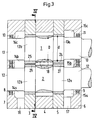
- Fig. 3
- eine Draufsicht auf einen Längsschnitt einer weiteren Ausführungsform der Einrichtung.
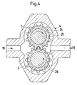
- Fig. 4
- einen Querschnitt gemäß IV-IV in Fig. 3.
- In Fig. 1 (Schnitt gemäß I-I in Fig. 2) werden zwei ein Dichtprofil miteinander bildende Zähne aufweisende Förderorgane 1 und 2 gezeigt, die in einem Gehäuse 4 angeordnet sind. Das Gehäuse 4 weist eine Materialeinlaßöffnung 18 sowie eine Auslaßöffnung 19 auf.
- Bei der in Fig. 2 gezeigten Draufsicht, wird durch "D" der Durchmesser des Fußkreises des Förderorganes 1 und durch "d" der Durchmesser der Wellenenden gezeigt.
- Die Förderorgane 1 und 2 sind in einem Gehäuse 4 angeordnet, welches auf beiden Seiten durch an dem Gehäuse 4 druckdicht befestigte Abdichtplatten 3 und 5 abgedichtet ist. Die Abdichtplatten 3 und 5 nehmen die Wellenendenteile 12a, 12b und 13a, 13b auf.
- An den Abdichtplatten 3 und 5 sind jeweils beidseitig die Lagerplatten 6 und 7 durch nicht gezeigte Verschraubungen befestigt. Die Lagerplatten 6 und 7 nehmen die Lager 8 und 9 für die beiderseitigen Wellenteile 12 und Lager 10 und 11 beiderseitigen Wellenteile 13 auf.
- Die Wellenteile 12a, 12b und 13a, 13b weisen darin eingebrachte wendelförmig ausgebildete Rückförderkanälen 20, 21, 22, 23 auf, um in den Spalt zwischen den Wellenteilen 12a, 12b und 13a, 13b und den Abdichtplatten 3 und 5 eingedrungenes Material wieder in den Raum zwischen den einzelnen Zähnen der Förderorgane 1 und 2 zurückzufördern.
- Sollte indessen die Förderleistung der Rückfördergewinde nicht ausreichen und trotzdem Material durch diese Spalte dringen, wird es in den Aufnahmekammern 15a, 15b und 15c bzw. am gegenüberliegenden Wellenende in den Aufnahmekammern 14a, 14b und 14c gesammelt.
- Das gesammelte Leckagematerial wird durch Abführkanäle 16 und 17 aus der Einrichtung herausgeführt, um zu vermeiden, daß Material in die Wellenlager 8, 9, 10 und 11 eindringt und dort Lagerschäden verursacht. Die Temperierung der Förderorgane 1 und 2 sowie der angrenzenden Wellenteile erfolgt durch Temperierbohrungen 28, an die ein nicht dargestelltes Umlauftemperiergerät anschließbar ist. Eine Temperierung der Förderorgane, d.h. in diesem Fall eine Kühlung, ist von großem Vorteil, weil dann die Förderleistung für hochviskose Kautschuke erheblich gesteigert werden kann, ohne daß eine punktuelle Anvulkanisation auftritt.
- Bei den erfindungsgemäßen Förderorganen 1 und 2 wird eine axiale Abdichtung der Wellenteile 12a, 12b und 13a, 13b durch die Rückfördergewinde 20, 21, 22 und 23 gewährleistet.
- Die radiale äußerst schwierig darzustellende Abdichtung wird auf eine sehr einfache Weise vermieden. Durch die Ausbildung der Wellenteile 12a, 12b und 13a, 13b mit einem Durchmesser d der etwa dem Fußkreisdurchmesser D der Förderorgane 1 und 2 entspricht entfällt eine Abdichtung an diesen Stellen, weil die kritischen Stirnflächen selbst vermieden werden.
- Die Herstellung der Zähne aufweisenden Förderorgane 1 und 2 aus einem Stück mit den angeformten Wellenteilen 12, 12a und 12b sowie 13, 13a und 13b ist sehr vorteilhaft.
- Durch das Aufschrumpfen von Hülsen 24, 25, 26 und 27 auf die Wellenteile 12a und 13a werden Durchmesser der Wellenteile erhalten, die exakt dem Durchmesser des Fußkreises D entsprechen oder auch größer sein können als der Durchmesser D des Fußkreises der Förderorgane 1 und 2, so daß jegliche radiale Abdichtungsprobleme vermieden werden.
- Aus Fig. 3 ist erkennbar, daß der Durchmesser d geringfügig größer ist als der Durchmesser D des Fußkreises. Abdichtungsprobleme und ein Anvulkanisieren von Kautschuk durch eine erhöhte Einleitung von Scherenergie entfallen somit.
-
- D
- = Fußkreisdurchmesser
- d
- = Wellendurchmesser
- 1a
- = Zahnrad
- 1b
- = Zahnrad
- 2
- = Gehäuse
- 3
- = Abdichtplatte
- 4
- = Förderraumgehäuse
- 5
- = Abdichtplatte
- 6
- = Lagerplatte (Glockenteil)
- 7
- = Lagerplatte (Glockenteil)
- 8
- = Lager (Wälzlager)
- 9
- = Lager (Wälzlager)
- 10
- = Lager
- 11
- = Lager
- 12
- = Wellenteil
- 12a
- = Wellenteil
- 12b
- = Wellenteil
- 13
- = Wellenteil
- 13a
- = Wellenteil
- 13b
- = Wellenteil
- 14a
- = Aufnahmekammer für Leckagematerial
- 14b
- = Aufnahmekammer für Leckagematerial
- 14c
- = Aufnahmekammer für Leckagematerial
- 15a
- = Aufnahmekammer für Leckagematerial
- 15b
- = Aufnahmekammer für Leckagematerial
- 15c
- = Aufnahmekammer für Leckagematerial
- 16
- = Abführkanäle für Leckagematerial
- 17
- = Abführkanäle für Leckagematerial
- 18
- = Einlaßöffnung
- 19
- = Auslaßöffnung
- 20
- = Rückfördergewinde
- 21
- = Rückfördergewinde
- 22
- = Rückfördergewinde
- 23
- = Rückfördergewinde
- 24
- = Hülse
- 25
- = Hülse
- 26
- = Hülse
- 27
- = Hülse
- 28
- = Temperierbohrungen
Claims (7)
- Einrichtung zum Erzeugen eines steuerbaren gleichmässigen Förderdruckes für die Verarbeitung von hochviskosem Kautschuk oder thermoplastischem Kunststoff, bestehend aus zwei, ein zahnartiges Dichtprofil bildenden, rotierenden auf Wellen in einem Gehäuse gelagerten Förderorganen, wobei das Gehäuse eine Einlaß- und Auslaßöffnung für das zu fördernde Material aufweist, die Förderorgane mit ihren beidseitigen Wellenenden in dem Gehäuse gelagert und allein oder gemeinsam antreibbar ausgebildet sind,
dadurch gekennzeichnet,
daß der Fußkreisdurchmesser (D) der das zahnartige Dichtprofil bildenden Förderorgane (1, 2) etwa dem Durchmesser (d) der axial beidseitig an den Förderorganen angrenzenden, die Führung der Förderorgane übernehmenden Wellenteile (12a, 13a) entspricht. - Einrichtung nach Anspruch 1,
dadurch gekennzeichnet,
daß das Förderorgan (1) und die Wellenenden (12, 12a, 12b) bzw. das Förderorgan (2) mit den Wellenenden (13, 13a, 13b) aus einem Stück hergestellt wird. - Einrichtung nach Anspruch 1,
dadurch gekennzeichnet,
daß der Durchmesser der Wellenteile (12a, 12b, 13a, 13b) durch aufgesetzte Hülsen (24, 25, 26 27) gleich oder geringfügig größer ausgebildet ist als der Fußkreisdurchmesser (D) der Förderorgane. - Einrichtung nach Anspruch 1,
dadurch gekennzeichnet,
daß in den Wellenteilen (12a, 12b, 13a, 13b) wendelförmig eingeformte Materialrückführungskanäle (20, 21, 22, 23) eingebracht sind. - Einrichtung nach den Ansprüchen 1 - 5,
dadurch gekennzeichnet,
daß das Gehäuse der Einrichtung gebildet wird durch eine- die Förderorgane (1, 2) aufnehmende Platte (4),- durch beidseitig daran angrenzende die Wellenteile (12a, 12b, 13a, 13b) aufnehmende Abdeckplatten (3, 5) und- durch beidseitig an die Abdeckplatten (3, 5) angrenzende, das Gehäuse abschließende und die Lagerung der Wellenenden (12, 13) aufnehmende Glockenteile (6, 7), mit darin eingebrachten Leckagematerial aufnehmende Kammern (14a, 14b, 15a, 15b). - Einrichtung nach Anspruch 1,
gekennzeichnet durch
auf den Wellenteilen (12a, 12b, 13a, 13b) aufgeschrumpfte Hülsen (24, 25, 26, 27). - Einrichtung nach Anspruch 1,
dadurch gekennzeichnet,
daß die Wellenteile (12, 12a, 12b, 13, 13a, 13b) sowie die Förderorgane (1, 2) Temperierbohrungen (28) aufweisen.
Applications Claiming Priority (2)
| Application Number | Priority Date | Filing Date | Title |
|---|---|---|---|
| DE4130312 | 1991-09-12 | ||
| DE4130312A DE4130312C1 (de) | 1991-09-12 | 1991-09-12 |
Publications (2)
| Publication Number | Publication Date |
|---|---|
| EP0535295A1 true EP0535295A1 (de) | 1993-04-07 |
| EP0535295B1 EP0535295B1 (de) | 1996-06-26 |
Family
ID=6440421
Family Applications (1)
| Application Number | Title | Priority Date | Filing Date |
|---|---|---|---|
| EP92104280A Expired - Lifetime EP0535295B1 (de) | 1991-09-12 | 1992-03-12 | Einrichtung zur Verarbeitung von hochviskosem Kautschuk oder thermoplastischem Kunststoff |
Country Status (4)
| Country | Link |
|---|---|
| US (1) | US5297866A (de) |
| EP (1) | EP0535295B1 (de) |
| JP (1) | JP3190438B2 (de) |
| DE (2) | DE4130312C1 (de) |
Cited By (1)
| Publication number | Priority date | Publication date | Assignee | Title |
|---|---|---|---|---|
| EP0599030A1 (de) * | 1992-10-23 | 1994-06-01 | Maag Pump Systems AG | Zahnradpumpe und deren Verwendungen |
Families Citing this family (5)
| Publication number | Priority date | Publication date | Assignee | Title |
|---|---|---|---|---|
| DE19635706C2 (de) * | 1996-09-03 | 1998-12-03 | Andreas Prof Dr Limper | Verfahren zum Plastifizieren, Sieben, Dosieren und Fördern hochviskoser Kautschukmischungen und Einrichtung für die Durchführung des Verfahrens |
| FR2828717A1 (fr) * | 2001-08-16 | 2003-02-21 | Michelin Soc Tech | Pompe a engrenage |
| JP5909966B2 (ja) * | 2011-09-30 | 2016-04-27 | 株式会社Lixil | ポンプ及び洗浄装置 |
| CN104389640B (zh) * | 2013-09-28 | 2017-09-05 | 摩尔动力(北京)技术股份有限公司 | 等模数齿轮流体机构及应用其的发动机 |
| DE102016225851A1 (de) * | 2016-12-21 | 2018-06-21 | Robert Bosch Gmbh | Außenzahnradpumpe für ein Abwärmerückgewinnungssystem |
Citations (6)
| Publication number | Priority date | Publication date | Assignee | Title |
|---|---|---|---|---|
| US2540235A (en) * | 1946-12-13 | 1951-02-06 | Hpm Dev Corp | Fluid operable apparatus |
| FR1277608A (fr) * | 1961-01-11 | 1961-12-01 | Sonic Engineering Company | Pompe rotative à décharge positive |
| US3072066A (en) * | 1958-04-07 | 1963-01-08 | Corken S Inc | Pump |
| GB1152326A (en) * | 1965-04-14 | 1969-05-14 | Onderzoekings Inst Res | Method and apparatus for Mixing Liquid Streams |
| US4439120A (en) * | 1980-10-27 | 1984-03-27 | Skega Ab | Meshing cog-wheel injection unit with lateral sealing and scropers |
| DE8814087U1 (de) * | 1988-11-10 | 1990-03-08 | Robert Bosch Gmbh, 7000 Stuttgart | Zahnradmaschine (Pumpe oder Motor) |
Family Cites Families (14)
| Publication number | Priority date | Publication date | Assignee | Title |
|---|---|---|---|---|
| US2369249A (en) * | 1939-10-24 | 1945-02-13 | Celanese Corp | Pumping device |
| US2892584A (en) | 1955-06-27 | 1959-06-30 | Emanuel S Briscoe | Vane-type rotary pumps |
| US3276387A (en) * | 1964-08-17 | 1966-10-04 | Lucas Industries Ltd | Gear pumps |
| DE1930540U (de) * | 1965-05-28 | 1966-01-05 | Barmag Barmer Maschf | Schneckenpresse zur verarbeitung thermoplastischer, insbesondere bereits vorplastifizierter bzw. frisch erschmolzener kunststoffe. |
| DE1553030A1 (de) * | 1965-10-12 | 1975-06-19 | Otto Eckerle | Spiel- und verschleissausgleichende hochdruck-zahnradpumpe bzw. -motor |
| NL6811174A (de) * | 1967-10-24 | 1969-04-28 | ||
| CH654879A5 (de) * | 1982-03-12 | 1986-03-14 | Maag Zahnraeder & Maschinen Ag | Zahnradmaschine, insbesondere zahnradpumpe fuer loesungen oder schmelzen von polymeren. |
| GB2169350B (en) * | 1985-01-05 | 1989-06-21 | Hepworth Plastics Ltd | Gear pumps |
| DE8514568U1 (de) * | 1985-05-17 | 1986-09-11 | Barmag Barmer Maschinenfabrik Ag, 5630 Remscheid | Drehkolbenpumpe, insbesondere Austragszahnradpumpe |
| DD247125A3 (de) * | 1985-09-23 | 1987-07-01 | Berlin Gummiwerke | Speisewalzenabdichtung |
| DE3917678A1 (de) * | 1989-05-31 | 1990-12-06 | Troester Maschf Paul | Vorrichtung und verfahren zum abdichten eines scherdornes oder einer schnecke einer extrusionsmaschine fuer kautschukmischungen und/oder kunststoffe |
| DE9011156U1 (de) * | 1990-07-28 | 1990-11-15 | Schneider, Friedhelm, 5226 Reichshof | Zahnradpumpe für hochviskose Flüssigkeiten |
| DE4125128C2 (de) * | 1990-08-10 | 1994-11-24 | Barmag Barmer Maschf | Zahnradpumpe |
| DE4111218C2 (de) * | 1991-04-07 | 1995-12-21 | Troester Maschf Paul | Zahnradpumpe für das Fördern von schwer verarbeitbaren Kautschukmischungen |
-
1991
- 1991-09-12 DE DE4130312A patent/DE4130312C1/de not_active Expired - Lifetime
-
1992
- 1992-03-12 DE DE59206650T patent/DE59206650D1/de not_active Expired - Fee Related
- 1992-03-12 EP EP92104280A patent/EP0535295B1/de not_active Expired - Lifetime
- 1992-08-04 JP JP20823292A patent/JP3190438B2/ja not_active Expired - Fee Related
- 1992-09-14 US US07/944,333 patent/US5297866A/en not_active Expired - Lifetime
Patent Citations (6)
| Publication number | Priority date | Publication date | Assignee | Title |
|---|---|---|---|---|
| US2540235A (en) * | 1946-12-13 | 1951-02-06 | Hpm Dev Corp | Fluid operable apparatus |
| US3072066A (en) * | 1958-04-07 | 1963-01-08 | Corken S Inc | Pump |
| FR1277608A (fr) * | 1961-01-11 | 1961-12-01 | Sonic Engineering Company | Pompe rotative à décharge positive |
| GB1152326A (en) * | 1965-04-14 | 1969-05-14 | Onderzoekings Inst Res | Method and apparatus for Mixing Liquid Streams |
| US4439120A (en) * | 1980-10-27 | 1984-03-27 | Skega Ab | Meshing cog-wheel injection unit with lateral sealing and scropers |
| DE8814087U1 (de) * | 1988-11-10 | 1990-03-08 | Robert Bosch Gmbh, 7000 Stuttgart | Zahnradmaschine (Pumpe oder Motor) |
Cited By (2)
| Publication number | Priority date | Publication date | Assignee | Title |
|---|---|---|---|---|
| EP0599030A1 (de) * | 1992-10-23 | 1994-06-01 | Maag Pump Systems AG | Zahnradpumpe und deren Verwendungen |
| US5549462A (en) * | 1992-10-23 | 1996-08-27 | Maag Pump Systems Ag | Gear pump and its uses |
Also Published As
| Publication number | Publication date |
|---|---|
| EP0535295B1 (de) | 1996-06-26 |
| DE59206650D1 (de) | 1996-08-01 |
| DE4130312C1 (de) | 1992-12-24 |
| US5297866A (en) | 1994-03-29 |
| JPH05195962A (ja) | 1993-08-06 |
| JP3190438B2 (ja) | 2001-07-23 |
Similar Documents
| Publication | Publication Date | Title |
|---|---|---|
| DE2158246C3 (de) | Vorrichtung zum Aufbereiten und Strangpressen von thermoplastischen Kunststoffen | |
| EP1523403B1 (de) | Extruder | |
| DE3520662A1 (de) | Wellendichtung fuer eine vorrichtung zur kontinuierlichen verarbeitung hochviskoser medien, insbesondere zur herstellung hochmolekularer polymere | |
| DE2625609B2 (de) | Entgasungsextruder | |
| EP0995565B1 (de) | Maschine zum kontinuierlichen Bearbeiten von fliessfähigen Materialen | |
| EP0558888A1 (de) | Einrichtung zur Verarbeitung von hochviskosem Kautschuk oder thermoplastischem Kunststoff | |
| EP2910783A1 (de) | Zweispindelige Schraubenspindelpumpe in einflutiger Bauweise | |
| EP0995566B1 (de) | Maschine zum kontinuierlichen Bearbeiten von fliessfähigen Materialen | |
| EP0535295A1 (de) | Einrichtung zur Verarbeitung von hochviskosem Kautschuk oder thermoplastischem Kunststoff | |
| DE4125128C2 (de) | Zahnradpumpe | |
| EP0602357A1 (de) | Zahnradpumpe | |
| DE3808723C1 (en) | Welding device | |
| EP0012795B1 (de) | Schneckenstrangpresse für die Verarbeitung von Kunststoff, Kautschuk oder dergleichen | |
| EP0564884B1 (de) | Mehrwellige Schneckenmaschine mit Zahnradpumpe | |
| EP0642913A1 (de) | Einwellenschnecke mit Zahnradpumpe | |
| EP0809567A1 (de) | Welle, insbesondere extruderwelle, die aus segmenten zusammengesetzt ist | |
| DE4308098A1 (de) | Planetwalzenextruder | |
| EP4244041B1 (de) | Multiwellen-aufbereitungseinheit für kunststoffschmelzen | |
| DE19920597A1 (de) | Aufnahmeeinrichtung für wenigstens eine in einem Gehäuse dichtend gelagerte Welle | |
| DE2802125A1 (de) | Schneckenmaschine zum bearbeiten von festen, fluessigen und zaehviskosen materialien | |
| DE2129839B2 (de) | Schneckenpresse fuer die verarbeitung und entgasung plastischer massen | |
| DE4207088C1 (en) | Feeder for high viscosity e.g. rubber - has sealed housing contg. two revolving toothed wheels with spiral flow bores which return leaked material back to feed gap | |
| EP0248196B1 (de) | Mehrwellige Schneckenmaschine mit Schneidelementen | |
| DE4132164A1 (de) | Gleitringdichtung fuer eine welle einer pumpe o. dgl. | |
| DE1953654C3 (de) | Biegsame Antriebs- oder Abtriebswelle an einer Pumpe oder einem Motor mit exzentrisch umlaufendem Rotor |
Legal Events
| Date | Code | Title | Description |
|---|---|---|---|
| PUAI | Public reference made under article 153(3) epc to a published international application that has entered the european phase |
Free format text: ORIGINAL CODE: 0009012 |
|
| AK | Designated contracting states |
Kind code of ref document: A1 Designated state(s): CH DE GB IT LI |
|
| 17P | Request for examination filed |
Effective date: 19930611 |
|
| 17Q | First examination report despatched |
Effective date: 19940817 |
|
| ITF | It: translation for a ep patent filed | ||
| GRAA | (expected) grant |
Free format text: ORIGINAL CODE: 0009210 |
|
| AK | Designated contracting states |
Kind code of ref document: B1 Designated state(s): CH DE GB IT LI |
|
| REG | Reference to a national code |
Ref country code: CH Ref legal event code: NV Representative=s name: R. A. EGLI & CO. PATENTANWAELTE |
|
| REF | Corresponds to: |
Ref document number: 59206650 Country of ref document: DE Date of ref document: 19960801 |
|
| GBT | Gb: translation of ep patent filed (gb section 77(6)(a)/1977) |
Effective date: 19960715 |
|
| PLBE | No opposition filed within time limit |
Free format text: ORIGINAL CODE: 0009261 |
|
| STAA | Information on the status of an ep patent application or granted ep patent |
Free format text: STATUS: NO OPPOSITION FILED WITHIN TIME LIMIT |
|
| 26N | No opposition filed | ||
| REG | Reference to a national code |
Ref country code: GB Ref legal event code: IF02 |
|
| PGFP | Annual fee paid to national office [announced via postgrant information from national office to epo] |
Ref country code: CH Payment date: 20080325 Year of fee payment: 17 |
|
| PGFP | Annual fee paid to national office [announced via postgrant information from national office to epo] |
Ref country code: GB Payment date: 20080320 Year of fee payment: 17 Ref country code: IT Payment date: 20080321 Year of fee payment: 17 |
|
| PGFP | Annual fee paid to national office [announced via postgrant information from national office to epo] |
Ref country code: DE Payment date: 20080321 Year of fee payment: 17 |
|
| REG | Reference to a national code |
Ref country code: CH Ref legal event code: PL |
|
| GBPC | Gb: european patent ceased through non-payment of renewal fee |
Effective date: 20090312 |
|
| PG25 | Lapsed in a contracting state [announced via postgrant information from national office to epo] |
Ref country code: DE Free format text: LAPSE BECAUSE OF NON-PAYMENT OF DUE FEES Effective date: 20091001 Ref country code: CH Free format text: LAPSE BECAUSE OF NON-PAYMENT OF DUE FEES Effective date: 20090331 Ref country code: LI Free format text: LAPSE BECAUSE OF NON-PAYMENT OF DUE FEES Effective date: 20090331 |
|
| PG25 | Lapsed in a contracting state [announced via postgrant information from national office to epo] |
Ref country code: GB Free format text: LAPSE BECAUSE OF NON-PAYMENT OF DUE FEES Effective date: 20090312 |
|
| PG25 | Lapsed in a contracting state [announced via postgrant information from national office to epo] |
Ref country code: IT Free format text: LAPSE BECAUSE OF NON-PAYMENT OF DUE FEES Effective date: 20090312 |