EP0535568A1 - Vorrichtung zum Reinigen von einem metallischen Band - Google Patents
Vorrichtung zum Reinigen von einem metallischen Band Download PDFInfo
- Publication number
- EP0535568A1 EP0535568A1 EP92116545A EP92116545A EP0535568A1 EP 0535568 A1 EP0535568 A1 EP 0535568A1 EP 92116545 A EP92116545 A EP 92116545A EP 92116545 A EP92116545 A EP 92116545A EP 0535568 A1 EP0535568 A1 EP 0535568A1
- Authority
- EP
- European Patent Office
- Prior art keywords
- metal strip
- hollow roll
- anode
- vacuum vessel
- electric discharge
- Prior art date
- Legal status (The legal status is an assumption and is not a legal conclusion. Google has not performed a legal analysis and makes no representation as to the accuracy of the status listed.)
- Withdrawn
Links
Images
Classifications
-
- H—ELECTRICITY
- H01—ELECTRIC ELEMENTS
- H01J—ELECTRIC DISCHARGE TUBES OR DISCHARGE LAMPS
- H01J37/00—Discharge tubes with provision for introducing objects or material to be exposed to the discharge, e.g. for the purpose of examination or processing thereof
- H01J37/32—Gas-filled discharge tubes
- H01J37/32431—Constructional details of the reactor
- H01J37/32733—Means for moving the material to be treated
- H01J37/32743—Means for moving the material to be treated for introducing the material into processing chamber
-
- B—PERFORMING OPERATIONS; TRANSPORTING
- B08—CLEANING
- B08B—CLEANING IN GENERAL; PREVENTION OF FOULING IN GENERAL
- B08B7/00—Cleaning by methods not provided for in a single other subclass or a single group in this subclass
-
- C—CHEMISTRY; METALLURGY
- C23—COATING METALLIC MATERIAL; COATING MATERIAL WITH METALLIC MATERIAL; CHEMICAL SURFACE TREATMENT; DIFFUSION TREATMENT OF METALLIC MATERIAL; COATING BY VACUUM EVAPORATION, BY SPUTTERING, BY ION IMPLANTATION OR BY CHEMICAL VAPOUR DEPOSITION, IN GENERAL; INHIBITING CORROSION OF METALLIC MATERIAL OR INCRUSTATION IN GENERAL
- C23G—CLEANING OR DE-GREASING OF METALLIC MATERIAL BY CHEMICAL METHODS OTHER THAN ELECTROLYSIS
- C23G5/00—Cleaning or de-greasing metallic material by other methods; Apparatus for cleaning or de-greasing metallic material with organic solvents
-
- H—ELECTRICITY
- H01—ELECTRIC ELEMENTS
- H01J—ELECTRIC DISCHARGE TUBES OR DISCHARGE LAMPS
- H01J37/00—Discharge tubes with provision for introducing objects or material to be exposed to the discharge, e.g. for the purpose of examination or processing thereof
- H01J37/32—Gas-filled discharge tubes
- H01J37/32431—Constructional details of the reactor
- H01J37/32733—Means for moving the material to be treated
- H01J37/32752—Means for moving the material to be treated for moving the material across the discharge
- H01J37/32761—Continuous moving
- H01J37/3277—Continuous moving of continuous material
-
- H—ELECTRICITY
- H01—ELECTRIC ELEMENTS
- H01J—ELECTRIC DISCHARGE TUBES OR DISCHARGE LAMPS
- H01J37/00—Discharge tubes with provision for introducing objects or material to be exposed to the discharge, e.g. for the purpose of examination or processing thereof
- H01J37/32—Gas-filled discharge tubes
- H01J37/34—Gas-filled discharge tubes operating with cathodic sputtering
- H01J37/3402—Gas-filled discharge tubes operating with cathodic sputtering using supplementary magnetic fields
- H01J37/3405—Magnetron sputtering
Definitions
- the present invention relates to a metal strip surface cleaning apparatus.
- the cleaning process by the ion-bombard treatment has been carried out as a pretreatment of the dry process of the metal strip.
- the above ion-bombard treatment is the type of so-called “anode magnetron” in which the magnet is arranged near the anode.
- the present invention has been developed to substantially eliminate the above-described disadvantages.
- the object of the present invention is therefore to provide a metal strip surface cleaning apparatus which is capable of cleaning the metal strip surface with high efficiency and high speed.
- the metal strip surface cleaning apparatus comprising a vacuum vessel; a rotatable hollow roll which is contained in the vacuum vessel and along which a metal strip is bent, the rotatable hollow roll consists of non-magnetic and conductive material and constitutes cathode; a magnet means which is arranged in the hollow roll in the range that the metal strip is bent; an anode which is supported on the internal surface of the vacuum vessel so that both side edges of the anode cover the hollow roll in the range that the magnet means is arranged; and an discharge-proof plate which is provided in the vicinity of both side edges of the anode, whereby a electric discharge space is formed between the anode and the hollow roll, and a electric discharge gas is fed to the electric discharge space.
- the vacuum vessel may be provided with two sealing nozzles and a metal strip may be inserted into the vacuum vessel via the sealing nozzle and may be bent along the hollow roll and may be extended to the outside of the vacuum vessel via the sealing nozzle, so that the metal strip is capable of traveling from the sealing nozzle of inlet side to the sealing nozzle of outlet side as being guided by the hollow roll.
- the side edge portion of the anode existing in the outlet side of the metal strip may be bent along the metal strip and may constitute an adherence-proof portion, a adherence-proof gas may be fed to the space between the adherence-proof portion and the metal strip.
- the magnetron discharge is concentrated on the range of bent portion of the metal strip on the hollow roll by means of the magnet arranged in the hollow roll and the discharge-proof plate provided in vicinity of both side edges of the anode, so the strip metal surface is cleaned with high spattering efficiency and high speed.
- the rotatable hollow roll is used as a cathode and the metal strip is bent on the hollow roll, so the path (space) for the metal strip to return is available and the installation space is saved.
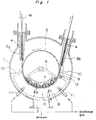
- a vacuum vessel 1 having circular cross section.
- a hollow roll 5 which constitutes a rotatable cathode is contained.
- the hollow roll 5 consists of non-magnetic and conductive material, for example, carbon, stainless steal, copper, copper alloy or metal material coated with conductive ceramic.
- the vacuum vessel 1 is provided with two sealing nozzles 3a, 3b.
- a metal strip W is inserted into the vacuum vessel 1 via the sealing nozzle 3a and is bent along the hollow roll 5 in a little over 1/3 range of the periphery of the hollow roll 5 and is extended to the outside of the vacuum vessel 1 via the sealing nozzle 3b, so that the metal strip W is capable of traveling from the sealing nozzle 3a of inlet side to the sealing nozzle 3b of outlet side as being guided by the hollow roll 5.
- a magnet holder 6 is attached on both internal end walls of the vacuum vessel 1.
- a permanent magnets 7 having longer length than the width of the metal strip W is arranged in the hollow roll 5 in the range that the metal strip W is bent and is held by the magnet holders 6, so that there exists a little gap between the outer surface of the permanent magnets 7 and the internal surface of the hollow roll 5.
- the permanent magnets 7 may be replaced by electromagnets.
- An anode 8 is supported on the internal surface of the hollow roll 5 with a small gap in the range opposed to the bent portion of the metal strip W. Both side edge portions of the anode 8 are bent and extended to the vicinity of the external surface of the hollow roll 5. Moreover the side edge portion of the anode 8 existing in the outlet side of the metal strip W is bent along the metal strip W and constitutes an adherence-proof portion 9. The space between the anode 8 and the hollow roll 5 (cathode) forms the electric discharge space 13. Alternatively, the anode 8 may be perforated.
- a discharge-proof plate 10 In the vicinity of both side edges of the anode 8 a discharge-proof plate 10 one end of which secured to the internal surface of the vacuum vessel 1 is provided respectively.
- the vacuum vessel 1 is provided with an exhaust port 2 to evacuate the vacuum vessel 1 with a vacuum pump not shown and hold a vacuum of 10 ⁇ 4 - 10 ⁇ 1 Torr.
- the vacuum vessel 1 is also provided with discharge gas inlet nozzles 11 to feed the discharge gas, for example, Argon gas into the electric discharge space 13.
- Aforementioned sealing nozzles 3a, 3b have an internal passage 4 of which cross sectional configuration is slightly larger than that of the metal strip W to prevent as much as possible the atmospheric air from infiltrating into the vacuum vessel 1.
- An adherence-proof gas nozzle 12 is provided in the vicinity of the adherence-proof portion 9.
- the metal strip surface cleaning apparatus described above is operated as follows.
- the vacuum vessel 1 is evacuated from the exhaust port 2 and is held a predetermined degree of vacuum, while the electric discharge gas is fed into the electric discharge space 13.
- a voltage is applied to the anode 8 and the hollow roll (cathode) 5 and then the metal strip W travels.
- the metal strip W constitutes the cathode because of being contacted with the hollow roll 5.
- the electric discharge therefore, occurs in the electric discharge space 13 between the metal strip W and the anode 8.
- the electron is trapped by the magnetic field formed by the permanent magnets 7 and makes cycloid motion on the metal strip W so that the ionization of the discharge gas is accelerated.
- the electric discharge is concentrated on the range opposed to the permanent magnets 7.
- the surface of the metal strip W traveling along the said range receives ion-bombard so that the surface is slightly etched and cleaned.
- the discharge-proof plate 10 prevents discharging in the range except for the electric discharge space 13.
- the particles, i.e., atom or molecule etc. spattered from the metal strip W are prevented from scattering and adhering to the metal strip W again by means of the gas flow fed from the adherence-proof gas inlet nozzle 12 to the space between the adherence-proof portion 9 and the metal strip W.
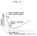
- the distance l1 between the anode 8 and the vacuum vessel 1 is comparatively smaller than the distance l2 between the anode 8 and the hollow roll (cathode) 5 (i.e., l1 is less than 1/3 of l2), for the electric discharge in the electric discharge space 13 having large anode-cathode distance starts at lower voltage than that in the space between the anode 8 and the vacuum vessel 1 having small distance according to Fig.2 showing the relation between anode-cathode distance and discharge starting voltage based on Paschen's law.
Landscapes
- Chemical & Material Sciences (AREA)
- Engineering & Computer Science (AREA)
- Physics & Mathematics (AREA)
- Plasma & Fusion (AREA)
- Analytical Chemistry (AREA)
- General Chemical & Material Sciences (AREA)
- Chemical Kinetics & Catalysis (AREA)
- Materials Engineering (AREA)
- Mechanical Engineering (AREA)
- Metallurgy (AREA)
- Organic Chemistry (AREA)
- Physical Vapour Deposition (AREA)
- ing And Chemical Polishing (AREA)
Applications Claiming Priority (2)
| Application Number | Priority Date | Filing Date | Title |
|---|---|---|---|
| JP251420/91 | 1991-09-30 | ||
| JP3251420A JPH0768620B2 (ja) | 1991-09-30 | 1991-09-30 | 金属ストリップの表面清浄化装置 |
Publications (1)
| Publication Number | Publication Date |
|---|---|
| EP0535568A1 true EP0535568A1 (de) | 1993-04-07 |
Family
ID=17222588
Family Applications (1)
| Application Number | Title | Priority Date | Filing Date |
|---|---|---|---|
| EP92116545A Withdrawn EP0535568A1 (de) | 1991-09-30 | 1992-09-28 | Vorrichtung zum Reinigen von einem metallischen Band |
Country Status (2)
| Country | Link |
|---|---|
| EP (1) | EP0535568A1 (de) |
| JP (1) | JPH0768620B2 (de) |
Cited By (9)
| Publication number | Priority date | Publication date | Assignee | Title |
|---|---|---|---|---|
| EP0780485A1 (de) * | 1995-12-20 | 1997-06-25 | RECHERCHE ET DEVELOPPEMENT DU GROUPE COCKERILL SAMBRE, en abrégé: RD-CS | Verfahren und Vorrichtung zum Reinigen eines Metallsubstrats |
| EP0878565A1 (de) * | 1997-04-10 | 1998-11-18 | RECHERCHE ET DEVELOPPEMENT DU GROUPE COCKERILL SAMBRE, en abrégé: RD-CS | Verfahren und Vorrichtung zum Ätzen |
| EP0908535A1 (de) * | 1997-10-08 | 1999-04-14 | RECHERCHE ET DEVELOPPEMENT DU GROUPE COCKERILL SAMBRE, en abrégé: RD-CS | Verfahren zum Reinigen eines Substrats und Vorrichtung zur Durchführung des Verfahrens |
| WO1999028520A3 (de) * | 1997-12-03 | 1999-07-15 | Fraunhofer Ges Forschung | Einrichtung zur behandlung von werkstücken in einem niederdruck-plasma |
| FR2774400A1 (fr) * | 1998-02-04 | 1999-08-06 | Physiques Et Chimiques | Dispositif electrique pour degraissage, decapage ou passivation plasmachimique de metaux |
| WO2004101844A1 (en) * | 2002-12-18 | 2004-11-25 | Cardinal Cg Company | Plasma-enhanced film deposition |
| EP0879897B2 (de) † | 1997-02-11 | 2006-08-02 | ARCELOR France | Verfahren zum Durchlaufglühen von Metallsubstraten |
| EP1783815A1 (de) * | 2005-11-07 | 2007-05-09 | ARCELOR France | Verfahren und Anlage zum Ätzen eines Metallbandes mittels Vakuum-Magnetron-Zerstäubung |
| US7931750B2 (en) | 2003-05-23 | 2011-04-26 | Arcelor France | Sealing lock for a deposition line in vacuum on a flat product |
Citations (6)
| Publication number | Priority date | Publication date | Assignee | Title |
|---|---|---|---|---|
| US2867912A (en) * | 1956-05-11 | 1959-01-13 | Horace Dawson | Method for the decontamination of metal foils |
| US4394236A (en) * | 1982-02-16 | 1983-07-19 | Shatterproof Glass Corporation | Magnetron cathode sputtering apparatus |
| WO1986007391A1 (fr) * | 1985-06-14 | 1986-12-18 | Leybold-Heraeus Gmbh | Procede et appareil d'enduction de substrats par decharge de plasma |
| EP0270144A1 (de) * | 1986-10-31 | 1988-06-08 | N.V. Bekaert S.A. | Verfahren und Vorrichtung zur kontinuierlichen Reinigung von langgestrecktem Gut und so gereinigte Gegenstände |
| US4896813A (en) * | 1989-04-03 | 1990-01-30 | Toyo Kohan Co., Ltd. | Method and apparatus for cold rolling clad sheet |
| EP0397952A1 (de) * | 1989-05-18 | 1990-11-22 | Nisshin Steel Co., Ltd. | Verfahren und Vorrichtung zum kontinuierlichen Ätzen und Beschichten von rostfreien Stahlbändern mit Aluminium |
-
1991
- 1991-09-30 JP JP3251420A patent/JPH0768620B2/ja not_active Expired - Fee Related
-
1992
- 1992-09-28 EP EP92116545A patent/EP0535568A1/de not_active Withdrawn
Patent Citations (6)
| Publication number | Priority date | Publication date | Assignee | Title |
|---|---|---|---|---|
| US2867912A (en) * | 1956-05-11 | 1959-01-13 | Horace Dawson | Method for the decontamination of metal foils |
| US4394236A (en) * | 1982-02-16 | 1983-07-19 | Shatterproof Glass Corporation | Magnetron cathode sputtering apparatus |
| WO1986007391A1 (fr) * | 1985-06-14 | 1986-12-18 | Leybold-Heraeus Gmbh | Procede et appareil d'enduction de substrats par decharge de plasma |
| EP0270144A1 (de) * | 1986-10-31 | 1988-06-08 | N.V. Bekaert S.A. | Verfahren und Vorrichtung zur kontinuierlichen Reinigung von langgestrecktem Gut und so gereinigte Gegenstände |
| US4896813A (en) * | 1989-04-03 | 1990-01-30 | Toyo Kohan Co., Ltd. | Method and apparatus for cold rolling clad sheet |
| EP0397952A1 (de) * | 1989-05-18 | 1990-11-22 | Nisshin Steel Co., Ltd. | Verfahren und Vorrichtung zum kontinuierlichen Ätzen und Beschichten von rostfreien Stahlbändern mit Aluminium |
Cited By (16)
| Publication number | Priority date | Publication date | Assignee | Title |
|---|---|---|---|---|
| BE1009839A3 (fr) * | 1995-12-20 | 1997-10-07 | Cockerill Rech & Dev | Procede et dispositif pour le nettoyage d'un substrat metallique. |
| EP0780485A1 (de) * | 1995-12-20 | 1997-06-25 | RECHERCHE ET DEVELOPPEMENT DU GROUPE COCKERILL SAMBRE, en abrégé: RD-CS | Verfahren und Vorrichtung zum Reinigen eines Metallsubstrats |
| EP0879897B2 (de) † | 1997-02-11 | 2006-08-02 | ARCELOR France | Verfahren zum Durchlaufglühen von Metallsubstraten |
| US6066241A (en) * | 1997-04-10 | 2000-05-23 | Recherche Et Development Du Groupe Cockerill Sambre En Abrege "Rdcs" | Pickling (etching) process and device |
| EP0878565A1 (de) * | 1997-04-10 | 1998-11-18 | RECHERCHE ET DEVELOPPEMENT DU GROUPE COCKERILL SAMBRE, en abrégé: RD-CS | Verfahren und Vorrichtung zum Ätzen |
| BE1011098A3 (fr) * | 1997-04-10 | 1999-04-06 | Cockerill Rech & Dev | Procede et dispositif de decapage. |
| US6231727B1 (en) | 1997-10-08 | 2001-05-15 | Recherche Et Developpement Du Groupe Cockerill Sambre, En Abrege Rd-Cs | Process for stripping the surface of a substrate and apparatus for implementing this process |
| EP0908535A1 (de) * | 1997-10-08 | 1999-04-14 | RECHERCHE ET DEVELOPPEMENT DU GROUPE COCKERILL SAMBRE, en abrégé: RD-CS | Verfahren zum Reinigen eines Substrats und Vorrichtung zur Durchführung des Verfahrens |
| WO1999028520A3 (de) * | 1997-12-03 | 1999-07-15 | Fraunhofer Ges Forschung | Einrichtung zur behandlung von werkstücken in einem niederdruck-plasma |
| FR2774400A1 (fr) * | 1998-02-04 | 1999-08-06 | Physiques Et Chimiques | Dispositif electrique pour degraissage, decapage ou passivation plasmachimique de metaux |
| WO2004101844A1 (en) * | 2002-12-18 | 2004-11-25 | Cardinal Cg Company | Plasma-enhanced film deposition |
| US7157123B2 (en) | 2002-12-18 | 2007-01-02 | Cardinal Cg Company | Plasma-enhanced film deposition |
| US7931750B2 (en) | 2003-05-23 | 2011-04-26 | Arcelor France | Sealing lock for a deposition line in vacuum on a flat product |
| EP1783815A1 (de) * | 2005-11-07 | 2007-05-09 | ARCELOR France | Verfahren und Anlage zum Ätzen eines Metallbandes mittels Vakuum-Magnetron-Zerstäubung |
| WO2007051917A1 (fr) * | 2005-11-07 | 2007-05-10 | Arcelormittal France | Procede et installation d’avivage sous vide par pulverisation magnetron d’une bande metallique |
| RU2369937C1 (ru) * | 2005-11-07 | 2009-10-10 | Арселормитталь Франс | Способ и установка для травления в вакууме при помощи магнетронного распыления металлической полосы |
Also Published As
| Publication number | Publication date |
|---|---|
| JPH0768620B2 (ja) | 1995-07-26 |
| JPH0593259A (ja) | 1993-04-16 |
Similar Documents
| Publication | Publication Date | Title |
|---|---|---|
| US6812648B2 (en) | Method of cleaning ion source, and corresponding apparatus/system | |
| EP0663019B1 (de) | Topographisch genaues duennfilm-beschichtungssystem | |
| US6117279A (en) | Method and apparatus for increasing the metal ion fraction in ionized physical vapor deposition | |
| KR100322330B1 (ko) | 재료의 이온 스퍼터링 방법 및 장치 | |
| JPS60155673A (ja) | 金属又は半導体の化合物の反応性スパツタリング法及びそのための装置 | |
| EP0801413A1 (de) | Induktivgekoppelter Plasmareaktor mit Zerstäubung verhinderndem Faraday-Schirm | |
| EP0535568A1 (de) | Vorrichtung zum Reinigen von einem metallischen Band | |
| GB2086434A (en) | Sputtering method and apparatus utilizing improved ion source | |
| EP0628986A1 (de) | Selbstreinigender Kollimator | |
| US5369337A (en) | DC or HF ion source | |
| US6988463B2 (en) | Ion beam source with gas introduced directly into deposition/vacuum chamber | |
| US5591313A (en) | Apparatus and method for localized ion sputtering | |
| JPH0831358A (ja) | Ecrイオンラジカル源 | |
| US5948294A (en) | Device for cathodic cleaning of wire | |
| US5240584A (en) | Apparatus for the reactive coating of a substrate | |
| JPH116049A (ja) | 真空成膜装置 | |
| US6342139B1 (en) | Sputtering system | |
| JPH07116598B2 (ja) | スパツタリング装置 | |
| US6471836B2 (en) | Sputtering apparatus | |
| JP4230564B2 (ja) | スパッタリング装置 | |
| JPH07258844A (ja) | 磁気中性線放電プラズマを利用した成膜装置 | |
| JPH0578829A (ja) | スパツタリング装置 | |
| KR0119732Y1 (ko) | 이온주입기의 이온소스장치 | |
| JPH02197567A (ja) | プラズマスパッタ装置 | |
| KR100397751B1 (ko) | 자성체 재료 코팅용 마그네트론 원 |
Legal Events
| Date | Code | Title | Description |
|---|---|---|---|
| PUAI | Public reference made under article 153(3) epc to a published international application that has entered the european phase |
Free format text: ORIGINAL CODE: 0009012 |
|
| AK | Designated contracting states |
Kind code of ref document: A1 Designated state(s): DE FR GB |
|
| 18W | Application withdrawn |
Withdrawal date: 19930809 |
|
| R18W | Application withdrawn (corrected) |
Effective date: 19930809 |