EP0535574A1 - Weiche dünne Bahnmaterialien mit durch Hydroschall eingebrachten Einbettungen und Verfahren zu deren Herstellung - Google Patents
Weiche dünne Bahnmaterialien mit durch Hydroschall eingebrachten Einbettungen und Verfahren zu deren Herstellung Download PDFInfo
- Publication number
- EP0535574A1 EP0535574A1 EP19920116573 EP92116573A EP0535574A1 EP 0535574 A1 EP0535574 A1 EP 0535574A1 EP 19920116573 EP19920116573 EP 19920116573 EP 92116573 A EP92116573 A EP 92116573A EP 0535574 A1 EP0535574 A1 EP 0535574A1
- Authority
- EP
- European Patent Office
- Prior art keywords
- film material
- soft film
- fibers
- thin soft
- thin
- Prior art date
- Legal status (The legal status is an assumption and is not a legal conclusion. Google has not performed a legal analysis and makes no representation as to the accuracy of the status listed.)
- Ceased
Links
Images



Classifications
-
- B—PERFORMING OPERATIONS; TRANSPORTING
- B32—LAYERED PRODUCTS
- B32B—LAYERED PRODUCTS, i.e. PRODUCTS BUILT-UP OF STRATA OF FLAT OR NON-FLAT, e.g. CELLULAR OR HONEYCOMB, FORM
- B32B37/00—Methods or apparatus for laminating, e.g. by curing or by ultrasonic bonding
-
- B—PERFORMING OPERATIONS; TRANSPORTING
- B29—WORKING OF PLASTICS; WORKING OF SUBSTANCES IN A PLASTIC STATE IN GENERAL
- B29C—SHAPING OR JOINING OF PLASTICS; SHAPING OF MATERIAL IN A PLASTIC STATE, NOT OTHERWISE PROVIDED FOR; AFTER-TREATMENT OF THE SHAPED PRODUCTS, e.g. REPAIRING
- B29C35/00—Heating, cooling or curing, e.g. crosslinking or vulcanising; Apparatus therefor
- B29C35/02—Heating or curing, e.g. crosslinking or vulcanizing during moulding, e.g. in a mould
- B29C35/0261—Heating or curing, e.g. crosslinking or vulcanizing during moulding, e.g. in a mould using ultrasonic or sonic vibrations
-
- B—PERFORMING OPERATIONS; TRANSPORTING
- B26—HAND CUTTING TOOLS; CUTTING; SEVERING
- B26F—PERFORATING; PUNCHING; CUTTING-OUT; STAMPING-OUT; SEVERING BY MEANS OTHER THAN CUTTING
- B26F1/00—Perforating; Punching; Cutting-out; Stamping-out; Apparatus therefor
- B26F1/26—Perforating by non-mechanical means, e.g. by fluid jet
-
- B—PERFORMING OPERATIONS; TRANSPORTING
- B29—WORKING OF PLASTICS; WORKING OF SUBSTANCES IN A PLASTIC STATE IN GENERAL
- B29C—SHAPING OR JOINING OF PLASTICS; SHAPING OF MATERIAL IN A PLASTIC STATE, NOT OTHERWISE PROVIDED FOR; AFTER-TREATMENT OF THE SHAPED PRODUCTS, e.g. REPAIRING
- B29C59/00—Surface shaping of articles, e.g. embossing; Apparatus therefor
- B29C59/02—Surface shaping of articles, e.g. embossing; Apparatus therefor by mechanical means, e.g. pressing
- B29C59/04—Surface shaping of articles, e.g. embossing; Apparatus therefor by mechanical means, e.g. pressing using rollers or endless belts
-
- B—PERFORMING OPERATIONS; TRANSPORTING
- B29—WORKING OF PLASTICS; WORKING OF SUBSTANCES IN A PLASTIC STATE IN GENERAL
- B29C—SHAPING OR JOINING OF PLASTICS; SHAPING OF MATERIAL IN A PLASTIC STATE, NOT OTHERWISE PROVIDED FOR; AFTER-TREATMENT OF THE SHAPED PRODUCTS, e.g. REPAIRING
- B29C70/00—Shaping composites, i.e. plastics material comprising reinforcements, fillers or preformed parts, e.g. inserts
- B29C70/58—Shaping composites, i.e. plastics material comprising reinforcements, fillers or preformed parts, e.g. inserts comprising fillers only, e.g. particles, powder, beads, flakes, spheres
- B29C70/64—Shaping composites, i.e. plastics material comprising reinforcements, fillers or preformed parts, e.g. inserts comprising fillers only, e.g. particles, powder, beads, flakes, spheres the filler influencing the surface characteristics of the material, e.g. by concentrating near the surface or by incorporating in the surface by force
-
- B—PERFORMING OPERATIONS; TRANSPORTING
- B32—LAYERED PRODUCTS
- B32B—LAYERED PRODUCTS, i.e. PRODUCTS BUILT-UP OF STRATA OF FLAT OR NON-FLAT, e.g. CELLULAR OR HONEYCOMB, FORM
- B32B27/00—Layered products comprising a layer of synthetic resin
- B32B27/06—Layered products comprising a layer of synthetic resin as the main or only constituent of a layer, which is next to another layer of the same or of a different material
- B32B27/08—Layered products comprising a layer of synthetic resin as the main or only constituent of a layer, which is next to another layer of the same or of a different material of synthetic resin
-
- B—PERFORMING OPERATIONS; TRANSPORTING
- B32—LAYERED PRODUCTS
- B32B—LAYERED PRODUCTS, i.e. PRODUCTS BUILT-UP OF STRATA OF FLAT OR NON-FLAT, e.g. CELLULAR OR HONEYCOMB, FORM
- B32B27/00—Layered products comprising a layer of synthetic resin
- B32B27/32—Layered products comprising a layer of synthetic resin comprising polyolefins
-
- B—PERFORMING OPERATIONS; TRANSPORTING
- B32—LAYERED PRODUCTS
- B32B—LAYERED PRODUCTS, i.e. PRODUCTS BUILT-UP OF STRATA OF FLAT OR NON-FLAT, e.g. CELLULAR OR HONEYCOMB, FORM
- B32B27/00—Layered products comprising a layer of synthetic resin
- B32B27/40—Layered products comprising a layer of synthetic resin comprising polyurethanes
-
- B—PERFORMING OPERATIONS; TRANSPORTING
- B32—LAYERED PRODUCTS
- B32B—LAYERED PRODUCTS, i.e. PRODUCTS BUILT-UP OF STRATA OF FLAT OR NON-FLAT, e.g. CELLULAR OR HONEYCOMB, FORM
- B32B5/00—Layered products characterised by the non- homogeneity or physical structure, i.e. comprising a fibrous, filamentary, particulate or foam layer; Layered products characterised by having a layer differing constitutionally or physically in different parts
- B32B5/16—Layered products characterised by the non- homogeneity or physical structure, i.e. comprising a fibrous, filamentary, particulate or foam layer; Layered products characterised by having a layer differing constitutionally or physically in different parts characterised by features of a layer formed of particles, e.g. chips, powder or granules
-
- B—PERFORMING OPERATIONS; TRANSPORTING
- B32—LAYERED PRODUCTS
- B32B—LAYERED PRODUCTS, i.e. PRODUCTS BUILT-UP OF STRATA OF FLAT OR NON-FLAT, e.g. CELLULAR OR HONEYCOMB, FORM
- B32B5/00—Layered products characterised by the non- homogeneity or physical structure, i.e. comprising a fibrous, filamentary, particulate or foam layer; Layered products characterised by having a layer differing constitutionally or physically in different parts
- B32B5/22—Layered products characterised by the non- homogeneity or physical structure, i.e. comprising a fibrous, filamentary, particulate or foam layer; Layered products characterised by having a layer differing constitutionally or physically in different parts characterised by the presence of two or more layers which are next to each other and are fibrous, filamentary, formed of particles or foamed
- B32B5/24—Layered products characterised by the non- homogeneity or physical structure, i.e. comprising a fibrous, filamentary, particulate or foam layer; Layered products characterised by having a layer differing constitutionally or physically in different parts characterised by the presence of two or more layers which are next to each other and are fibrous, filamentary, formed of particles or foamed one layer being a fibrous or filamentary layer
- B32B5/26—Layered products characterised by the non- homogeneity or physical structure, i.e. comprising a fibrous, filamentary, particulate or foam layer; Layered products characterised by having a layer differing constitutionally or physically in different parts characterised by the presence of two or more layers which are next to each other and are fibrous, filamentary, formed of particles or foamed one layer being a fibrous or filamentary layer another layer next to it also being fibrous or filamentary
-
- B—PERFORMING OPERATIONS; TRANSPORTING
- B32—LAYERED PRODUCTS
- B32B—LAYERED PRODUCTS, i.e. PRODUCTS BUILT-UP OF STRATA OF FLAT OR NON-FLAT, e.g. CELLULAR OR HONEYCOMB, FORM
- B32B2262/00—Composition or structural features of fibres which form a fibrous or filamentary layer or are present as additives
- B32B2262/02—Synthetic macromolecular fibres
- B32B2262/0253—Polyolefin fibres
-
- B—PERFORMING OPERATIONS; TRANSPORTING
- B32—LAYERED PRODUCTS
- B32B—LAYERED PRODUCTS, i.e. PRODUCTS BUILT-UP OF STRATA OF FLAT OR NON-FLAT, e.g. CELLULAR OR HONEYCOMB, FORM
- B32B2262/00—Composition or structural features of fibres which form a fibrous or filamentary layer or are present as additives
- B32B2262/02—Synthetic macromolecular fibres
- B32B2262/0261—Polyamide fibres
-
- B—PERFORMING OPERATIONS; TRANSPORTING
- B32—LAYERED PRODUCTS
- B32B—LAYERED PRODUCTS, i.e. PRODUCTS BUILT-UP OF STRATA OF FLAT OR NON-FLAT, e.g. CELLULAR OR HONEYCOMB, FORM
- B32B2262/00—Composition or structural features of fibres which form a fibrous or filamentary layer or are present as additives
- B32B2262/06—Vegetal fibres
- B32B2262/062—Cellulose fibres, e.g. cotton
- B32B2262/067—Wood fibres
-
- B—PERFORMING OPERATIONS; TRANSPORTING
- B32—LAYERED PRODUCTS
- B32B—LAYERED PRODUCTS, i.e. PRODUCTS BUILT-UP OF STRATA OF FLAT OR NON-FLAT, e.g. CELLULAR OR HONEYCOMB, FORM
- B32B2262/00—Composition or structural features of fibres which form a fibrous or filamentary layer or are present as additives
- B32B2262/10—Inorganic fibres
- B32B2262/103—Metal fibres
-
- B—PERFORMING OPERATIONS; TRANSPORTING
- B32—LAYERED PRODUCTS
- B32B—LAYERED PRODUCTS, i.e. PRODUCTS BUILT-UP OF STRATA OF FLAT OR NON-FLAT, e.g. CELLULAR OR HONEYCOMB, FORM
- B32B2310/00—Treatment by energy or chemical effects
- B32B2310/028—Treatment by energy or chemical effects using vibration, e.g. sonic or ultrasonic
-
- B—PERFORMING OPERATIONS; TRANSPORTING
- B32—LAYERED PRODUCTS
- B32B—LAYERED PRODUCTS, i.e. PRODUCTS BUILT-UP OF STRATA OF FLAT OR NON-FLAT, e.g. CELLULAR OR HONEYCOMB, FORM
- B32B2323/00—Polyalkenes
- B32B2323/04—Polyethylene
-
- B—PERFORMING OPERATIONS; TRANSPORTING
- B32—LAYERED PRODUCTS
- B32B—LAYERED PRODUCTS, i.e. PRODUCTS BUILT-UP OF STRATA OF FLAT OR NON-FLAT, e.g. CELLULAR OR HONEYCOMB, FORM
- B32B2323/00—Polyalkenes
- B32B2323/10—Polypropylene
-
- Y—GENERAL TAGGING OF NEW TECHNOLOGICAL DEVELOPMENTS; GENERAL TAGGING OF CROSS-SECTIONAL TECHNOLOGIES SPANNING OVER SEVERAL SECTIONS OF THE IPC; TECHNICAL SUBJECTS COVERED BY FORMER USPC CROSS-REFERENCE ART COLLECTIONS [XRACs] AND DIGESTS
- Y10—TECHNICAL SUBJECTS COVERED BY FORMER USPC
- Y10S—TECHNICAL SUBJECTS COVERED BY FORMER USPC CROSS-REFERENCE ART COLLECTIONS [XRACs] AND DIGESTS
- Y10S428/00—Stock material or miscellaneous articles
- Y10S428/902—High modulus filament or fiber
-
- Y—GENERAL TAGGING OF NEW TECHNOLOGICAL DEVELOPMENTS; GENERAL TAGGING OF CROSS-SECTIONAL TECHNOLOGIES SPANNING OVER SEVERAL SECTIONS OF THE IPC; TECHNICAL SUBJECTS COVERED BY FORMER USPC CROSS-REFERENCE ART COLLECTIONS [XRACs] AND DIGESTS
- Y10—TECHNICAL SUBJECTS COVERED BY FORMER USPC
- Y10T—TECHNICAL SUBJECTS COVERED BY FORMER US CLASSIFICATION
- Y10T428/00—Stock material or miscellaneous articles
- Y10T428/24—Structurally defined web or sheet [e.g., overall dimension, etc.]
- Y10T428/24273—Structurally defined web or sheet [e.g., overall dimension, etc.] including aperture
-
- Y—GENERAL TAGGING OF NEW TECHNOLOGICAL DEVELOPMENTS; GENERAL TAGGING OF CROSS-SECTIONAL TECHNOLOGIES SPANNING OVER SEVERAL SECTIONS OF THE IPC; TECHNICAL SUBJECTS COVERED BY FORMER USPC CROSS-REFERENCE ART COLLECTIONS [XRACs] AND DIGESTS
- Y10—TECHNICAL SUBJECTS COVERED BY FORMER USPC
- Y10T—TECHNICAL SUBJECTS COVERED BY FORMER US CLASSIFICATION
- Y10T428/00—Stock material or miscellaneous articles
- Y10T428/24—Structurally defined web or sheet [e.g., overall dimension, etc.]
- Y10T428/24273—Structurally defined web or sheet [e.g., overall dimension, etc.] including aperture
- Y10T428/24322—Composite web or sheet
- Y10T428/24331—Composite web or sheet including nonapertured component
-
- Y—GENERAL TAGGING OF NEW TECHNOLOGICAL DEVELOPMENTS; GENERAL TAGGING OF CROSS-SECTIONAL TECHNOLOGIES SPANNING OVER SEVERAL SECTIONS OF THE IPC; TECHNICAL SUBJECTS COVERED BY FORMER USPC CROSS-REFERENCE ART COLLECTIONS [XRACs] AND DIGESTS
- Y10—TECHNICAL SUBJECTS COVERED BY FORMER USPC
- Y10T—TECHNICAL SUBJECTS COVERED BY FORMER US CLASSIFICATION
- Y10T428/00—Stock material or miscellaneous articles
- Y10T428/249921—Web or sheet containing structurally defined element or component
-
- Y—GENERAL TAGGING OF NEW TECHNOLOGICAL DEVELOPMENTS; GENERAL TAGGING OF CROSS-SECTIONAL TECHNOLOGIES SPANNING OVER SEVERAL SECTIONS OF THE IPC; TECHNICAL SUBJECTS COVERED BY FORMER USPC CROSS-REFERENCE ART COLLECTIONS [XRACs] AND DIGESTS
- Y10—TECHNICAL SUBJECTS COVERED BY FORMER USPC
- Y10T—TECHNICAL SUBJECTS COVERED BY FORMER US CLASSIFICATION
- Y10T428/00—Stock material or miscellaneous articles
- Y10T428/25—Web or sheet containing structurally defined element or component and including a second component containing structurally defined particles
- Y10T428/253—Cellulosic [e.g., wood, paper, cork, rayon, etc.]
-
- Y—GENERAL TAGGING OF NEW TECHNOLOGICAL DEVELOPMENTS; GENERAL TAGGING OF CROSS-SECTIONAL TECHNOLOGIES SPANNING OVER SEVERAL SECTIONS OF THE IPC; TECHNICAL SUBJECTS COVERED BY FORMER USPC CROSS-REFERENCE ART COLLECTIONS [XRACs] AND DIGESTS
- Y10—TECHNICAL SUBJECTS COVERED BY FORMER USPC
- Y10T—TECHNICAL SUBJECTS COVERED BY FORMER US CLASSIFICATION
- Y10T428/00—Stock material or miscellaneous articles
- Y10T428/29—Coated or structually defined flake, particle, cell, strand, strand portion, rod, filament, macroscopic fiber or mass thereof
- Y10T428/2913—Rod, strand, filament or fiber
-
- Y—GENERAL TAGGING OF NEW TECHNOLOGICAL DEVELOPMENTS; GENERAL TAGGING OF CROSS-SECTIONAL TECHNOLOGIES SPANNING OVER SEVERAL SECTIONS OF THE IPC; TECHNICAL SUBJECTS COVERED BY FORMER USPC CROSS-REFERENCE ART COLLECTIONS [XRACs] AND DIGESTS
- Y10—TECHNICAL SUBJECTS COVERED BY FORMER USPC
- Y10T—TECHNICAL SUBJECTS COVERED BY FORMER US CLASSIFICATION
- Y10T428/00—Stock material or miscellaneous articles
- Y10T428/29—Coated or structually defined flake, particle, cell, strand, strand portion, rod, filament, macroscopic fiber or mass thereof
- Y10T428/2913—Rod, strand, filament or fiber
- Y10T428/2933—Coated or with bond, impregnation or core
Definitions
- the field of the present invention encompasses film materials having fibers and/or particulates embedded therein.
- Ultrasonics is basically the science of the effects of sound vibrations beyond the limit of audible frequencies. Ultrasonics has been used in a wide variety of applications. For example, ultrasonics has been used for (1) dust, smoke and mist precipitation; (2) preparation of colloidal dispersions; (3) cleaning of metal parts and fabrics; (4) friction welding; (5) the formation of catalysts; (6) the degassing and solidification of molten metals; (7) the extraction of flavor oils in brewing; (8) electroplating; (9) drilling hard materials; (10) fluxless soldering and (10) nondestructive testing such as in diagnostic medicine.
- the object of high power ultrasonic applications is to bring about some permanent physical change in the material treated. This process requires the flow of vibratory power per unit of area or volume. Depending on the application, the power density may range from less than a watt to thousands of watts per square centimeter. Although the original ultrasonic power devices operated at radio frequencies, today most operate at 20-69 kHz.
- the piezoelectric sandwich-type transducer driven by an electronic power supply has emerged as the most common source of ultrasonic power.
- the overall efficiency of such equipment (net acoustic power per electric-line power) is typically greater than 70%.
- the maximum power from a conventional transducer is inversely proportional to the square of the frequency.
- ultrasonic force has been use to bond or weld nonwoven webs. See, for example, U.S. patent numbers 3,575,752 to Carpenter , 3,660,186 to Sager et al. , 3,966,519 to Mitchell et al. and 4,695,454 to Sayovitz et al. which disclose the use of ultrasonics to bond or weld nonwoven webs.
- U.S. patent number 3,488,240 to Roberts describes the use of ultrasonics to bond or weld thin films such as oriented polyesters.
- Ultrasonic force has also been utilized to aperture nonwoven webs. See, for example, U.S. patent numbers 3,949,127 to Ostermeier et al. and 3,966,519 to Mitchell et al. .
- U.S. patent number 4,815,714 to Douglas discusses the aperturing of a thin film by first abrading the film, which is in filled and unoriented form, and then subjecting the film to corona discharge treatment.
- soft material refers to any material that is capable of having fibers or particulates embedded therein by hydrosonic processing.
- soft materials include, without limitation, certain thermoplastic film materials and certain materials derived from natural materials. Some experimentation is necessary because if the material is too hard fibers and/or particulates cannot be embedded therein. Conversely, if the material is too elastic fibers and particulates cannot be embedded because, it is believed, they bounce off of the material during hydrosonic processing.
- soft film material refers to a generally nonporous film formed from a material that can be arranged in generally planar configuration which. This term is also intended to include multilayer materials which include, as a surface layer thereof, at least one such soft film material as a layer thereof.
- thin soft film material refers to a soft film material having an average thickness generally of less than about ten (10) mils. Average thickness is determined by randomly selecting five (5) locations on a given film material, measuring the thickness of the film material at each location to the nearest 0.1 mil, and averaging the five values (sum of the five values divided by five).
- the term "mesh count” refers to the number which is the product of the number of wires in a wire mesh screen in both the machine (MD) and cross-machine (CD) directions in a given unit area.
- MD machine
- CD cross-machine
- a wire mesh screen having 100 wires per inch in the machine direction and 100 wires per inch in the cross machine direction would have a mesh count of 10,000 per square inch.
- raised areas are present on both sides of the mesh screen.
- the number of raised areas on one side of such a wire mesh screen is generally one-half of the mesh count.
- aperture refers to a generally linear hole or passageway. Aperture is to be distinguished from and does not include holes or passageways having the greatly tortuous path or passageways found in membranes.
- microaperture refers to an aperture which has an area of less than about 100,000 square micrometers. The area of the microaperture is to be measured at the narrowest point in the linear passageway or hole.
- ultrasonic vibrations refers to vibrations having a frequency of at least about 20,000 cycles per second.
- the frequency of the ultrasonic vibrations may range from about 20,000 to about 400,000 cycles per second.
- hydrosonics refers to the application of ultrasonic vibrations to a material where the area of such application is has had a liquid applied thereto to the extent that the liquid is present in sufficient quantity to generally fill the gap between the tip of the ultrasonic horn and the surface of the material.
- thin sheet materials may be microapertured if they are subjected to hydrosonic treatment against an anvil where the anvil is a pattern anvil having a pattern of raised areas that have a height which is greater than the thickness of the thin sheet material to be apertured. While conducting the experiments discussed in detail in the referenced related applications, some experiments were conducted to determine whether the presence of solids in the fluid would affect the microaperturing process. Much to our surprise, not only was the microaperturing process generally not affected, but we discovered that the hydrosonic force actually embedded the fibers and particulates which we had added to the coupling fluid to act as impurities into the sheet material while the sheet material was still apertured.
- the fibers to be embedded may be of any type which is able to withstand hydrosonic treatment.
- the fibers to be embedded may be selected from the group including metallic fibers such as are found in steel wool; naturally occurring fibers such as, for example, wood pulp fibers, cotton fibers and wool fibers; and synthetic fibers such as polyolefin fibers, rayon fibers and nylon fibers.
- the particulates to be embedded may be of any type which is able to withstand hydrosonic treatment.
- the particulates may be selected from the group including calcium carbonate, silicon carbide, diamond or activated charcoal. In some embodiments both fibers and particulates may be embedded into the thin soft film material.
- the thin soft film material may be formed from the group of materials selected from the group including soft polypropylenes, soft polyethylenes, soft urethanes, soft alginates or carrageenan.
- the thin soft film which is embedded with fibers and/or particulates may also be microapertured so that it defines at least about 1,000 microapertures per square inch.
- the thin soft film material which is embedded with fibers and/or particulates may also be microapertured so that it defines at least about 5,000 microapertures per square inch.
- the thin soft film material which is embedded with fibers and/or particulates may also be microapertured so that it defines at least about 20,000 microapertures per square inch.
- the thin soft film material which is embedded with fibers and/or particulates may also be microapertured so that it defines at least about 90,000 microapertures per square inch.
- the thin soft film material which is embedded with fibers and/or particulates may also be microapertured so that it defines at least about 160,000 microapertures per square inch.
- the average thickness of the thin soft film material is less than about ten mils. Additionally, the average thickness of the thin soft film material is at least about 0.25 mil. For example, the average thickness of the thin soft film material may range from at least about 0.25 mil to about 5 mils. More particularly, the average thickness of the film material may range from at least about 0.25 mil to about 2 mils. Even more particularly, the average thickness of the film material may range from at least about 0.5 mil to about 1 mil.
- the invention also is directed to a method for embedding fibers and/or particulates, or both, in a thin soft film material.
- the process includes the steps of (a) placing the thin soft film material on an anvil means; (b) conveying the thin soft film material, while placed on the anvil means, through an area where a mixture of a fluid and fibers and/or particulates, or both, is applied to the thin soft film material; and (c) subjecting the thin soft film material to a sufficient amount of ultrasonic vibrations in the area where the fluid and fibers and/or particulates, or both, are applied to the thin soft film material to embed the fibers, particulates or both into the thin soft film material.
- the fluid may be selected from the group including one or more of water, mineral oil, a chlorinated hydrocarbon, ethylene glycol or a solution of 50 volume percent water and 50 volume percent 2 propanol.
- the chlorinated hydrocarbon may be selected form the group including 1,1,1 trichloroethane or carbon tetrachloride.
- the embedding may be confined to a predesignated area or areas of the soft thin film. This result may be obtained where only a portion of the soft thin film is subjected to ultrasonic vibrations.
- the anvil means may be selected from the group including a smooth, nonpatterned, stainless steel shim material or a smooth, non-patterned roller coated with a resilient material.
- the anvil means should be a pattern anvil mechanism having a pattern of raised areas.
- Figure I is a schematic representation of apparatus which utilizes ultrasonic vibrations to embed fibers and/or particulates in thin soft film materials.
- Figure II is a cross sectional view of the transport mechanism for transporting the thin soft film material to the area where it is subjected to ultrasonic vibrations.
- Figure III is a detailed view of the area where the thin soft film material is subjected to ultrasonic vibrations. The area is designated by the dotted circle in Figure I.
- Figure IV is a photomicrograph of a 0.5 mil thick thin soft film of polyethylene which has had southern softwood fibers embedded therein in accordance with the present invention.
- the photomicrograph is accompanied by a scale where each unit represents ten microns (micrometers).
- Figure V is a photomicrograph of a 0.5 mil thick thin soft film of polyethylene which has been microapertured and has had southern softwood fibers embedded therein in accordance with the present invention.
- the photomicrograph is accompanied by a scale where each unit represents ten microns (micrometers).
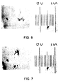
- Figure VI is a photomicrograph of a 0.5 mil thick thin soft film of polyethylene which has been microapertured and has had calcium carbonate particulates embedded therein in accordance with the present invention.
- the photomicrograph is accompanied by a scale where each unit represents ten microns (micrometers).
- Figure VII is a photomicrograph of a 0.5 mil thick thin soft film of polyethylene which has been microapertured and has had silicon carbide particulates embedded therein in accordance with the present invention.
- the photomicrograph is accompanied by a scale where each unit represents ten microns (micrometers).
- a supply roll 12 of a thin soft film material 14 into which fibers, particulates, or both are to be embedded is supplied.
- the term thin soft film material refers to film materials which have an average thickness of about ten (10) mils or less. Additionally, generally speaking the average thickness of the thin soft film material 14 will be at least about 0.25 mil. For example, the average thickness of the thin soft film 14 material may range from about 0.25 mil to about 5 mils. More particularly, the average thickness of the thin soft film material 14 may range from about 0.25 mil to about 2 mils. Even more specifically, the average thickness of the thin soft film material 14 may range from about 0.5 mil to about 1 mil.
- the thin soft film material 14 may be formed from any suitable material meeting the definition of soft contained herein.
- the thin soft film material may be formed from soft materials such as soft polyolefins such as, for example, soft polypropylenes or soft polyethylenes; soft urethanes or soft alginlates such as carrageenan.
- the thin soft film material 14 is transported to a first nip 16 formed by a first transport roll 18 and a first nip roller 20 by the action of an endless transport mechanism 22 which moves in the direction indicated by the arrow 24.
- the transport mechanism 22 is driven by the rotation of the first transport roller 18 in conjunction with a second transport roller 26 which, in turn, are driven by a conventional power source, not shown.
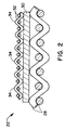
- Figure II is a cross sectional view of the transport mechanism 22 taken along lines A-A in Figure I.
- Figure II discloses that the transport mechanism 22 includes a heavy duty transport wire mesh screen 28 usually having a mesh count of less than about 400 (i.e. less than a 20 wires per inch MD by 20 wires per inch CD mesh screen if machine direction (MD) and cross machine direction (CD) wire count is the same).
- Heavy duty mesh wire screens of this type may be made from a variety of materials such as, for example, plastics, nylons or polyesters, and are readily available to those in the art.
- Located above and attached to the transport screen 28 is an endless flat shim plate 30.
- the shim plate 30 desirably is formed from stainless steel. However, those of skill in the art will readily recognize that other materials may be utilized.
- the thin soft film material 14 is transported by the transport mechanism 22 over a tension roll 36 to an area 38 (defined in Figure I by the dotted lined circle) where the thin soft film material 14 is subjected to ultrasonic vibrations.
- the assembly for subjecting the thin soft film material 14 to the ultrasonic vibrations is conventional and is generally designated at 40.
- the assembly 40 includes a power supply 42 which, through a power control 44, supplies power to a piezoelectric transducer 46.
- the piezoelectric transducer 46 transforms electrical energy into mechanical movement as a result of the transducer's vibrating in response to an input of electrical energy.
- the vibrations created by the piezoelectric transducer 46 are transferred, in conventional manner, to a mechanical movement booster or amplifier 48.
- the mechanical movement booster 48 may be designed to increase the amplitude of the vibrations (mechanical movement) by a known factor depending upon the configuration of the booster 48.
- the mechanical movement is transferred from the mechanical movement booster 48 to a conventional knife edge ultrasonic horn 50.
- a conventional knife edge ultrasonic horn 50 could be utilized.
- the ultrasonic horn 50 may be designed to effect yet another boost or increase in the amplitude of the mechanical movement (vibrations) which is to be applied to the thin soft film material 14.
- the assembly includes an actuator 52 which includes a pneumatic cylinder, not shown. The actuator 52 provides a mechanism for raising and lowering the assembly 40 so that the tip 54 of the ultrasonic horn 50 can apply tension to the transport mechanism 22 upon the assembly 40 being lowered.
- Figure III is a schematic representation of the area 38 where the ultrasonic vibrations are applied to the thin soft film material 14.
- the transport mechanism 22 forms an angle 56 with the tip 54 of the ultrasonic horn 50. While some embedding will occur if the angle 56 is as great as 45 degrees, it has been found that it is desirable for the angle 56 to range from about 5 degrees to about 15 degrees. For example, the angle 56 may range from about 7 to about 13 degrees. More particularly, the angle 56 may range from about 9 to about 11 degrees.
- Figure III also illustrates that the transport mechanism 22 is supported from below by the first tension roll 36 and a second tension roll 58.
- a spray nozzle 60 Positioned somewhat prior to the tip 54 of the ultrasonic horn 50 is a spray nozzle 60 which is configured to apply a mixture of a fluid and the fibers, particulates, etc. 62 which are to be embedded into the surface of the thin soft film material 14 just prior to the sheet material 14 being subjected to ultrasonic vibrations by the tip 54 of the ultrasonic horn 50.
- the fluid portion of the mixture 62 desirably may be selected from the group including one or more of water, mineral oil, a chlorinated hydrocarbon, ethylene glycol or a solution of 50 volume percent water and 50 volume percent 2 propanol.
- the chlorinated hydrocarbon may be selected from the group including 1,1,1 trichloroethane or carbon tetrachloride.
- the fibers and/or particulates or both which may be utilized in the mixture 62 may be any type of fibers having sufficient rigidity to allow there being embedded into the thin soft film material 14.
- the fibers may be selected from the group including metallic fibers such as are found in steel wool; naturally occurring fibers such as, for example, wood pulp fibers, cotton fibers and wool fibers; and synthetic fibers such as polyolefin fibers, rayon fibers and nylon fibers.
- the particulates to be embedded may be of any type which is able to withstand hydrosonic treatment.
- the particulates may be selected from the group including calcium carbonate, silicon carbide, diamond or activated charcoal.
- the wedge-shaped area 64 formed by the tip 54 of the ultrasonic horn 50 and the transport mechanism 22 should be subjected to a sufficient amount of the mixture 62 for the fluid to act as both a heat sink and a coupling agent for the most desirable results.
- a mixture collection tank 66 Positioned below the transport mechanism 22 in the area where the tip 54 of the ultrasonic horn 50 is located is a mixture collection tank 66. (See Figure I.)
- the mixture collection tank 66 serves to collect mixture 62 which has been applied to the surface of the thin soft film material 14 and which has been driven through the transport mechanism 22 or over the edges of the transport mechanism 22 by the action of the vibrations of the tip 54 of the ultrasonic horn 50.
- Mixture 62 which is collected in the collection tank 66 is transported by tubing 68 to a mixture holding tank 70.
- Figure I illustrates that the mixture holding tank 70 contains a pump 72 which, by way of additional tubing 74, supplies the mixture 62 to the mixture spray nozzle 60. Accordingly, the mixture 62 may be recycled for a considerable period of time.
- the presence of the fluid portion of the mixture 62 in the wedge-shaped area 64 during operation of the ultrasonic horn 50 accomplishes two separate and distinct functions.
- the presence of the fluid portion allows the fluid to act as a heat sink which allows the ultrasonic vibrations to be applied to the thin soft film material 14 without the thin soft film material 14 being altered or destroyed as by melting.
- the presence of the fluid portion of the mixture 62 in the wedge-shaped area 64 allows the fluid to act as a coupling agent in the application of the vibrations from the ultrasonic horn 50 to the thin soft film material 14.
- fine mesh wire pattern screen 32 usually having a mesh count of at least about 2,000 (i.e. at least about 45 wires per inch MD by 45 wires per inch CD mesh screen if MD and CD wire count is the same). Fine mesh wire screens of this type are readily available to those in the art.
- the fine mesh wire screen 32 has raised areas or knuckles 34 which preform the function of a pattern anvil as will be discussed later.
- the microapertures are punched through the thin soft film material 14 in the pattern of the raised areas or knuckles 34 of the fine mesh wire pattern screen 32.
- the number of microapertures produced will be equal to the number of raised areas or knuckles 34 on the upper surface of the fine mesh wire screen 32. That is, the number of microapertures will generally be one-half the mesh count of a given area of pattern screen 32. For example, if the pattern screen 32 is 100 wires per inch MD by 100 wires per inch CD, the total number of knuckles or raised areas 34 on one side of the pattern wire, per square inch, 32 will be 100 times 100 divided by 2.
- the number of microapertures formed may also vary with the number of ultrasonic vibrations to which the thin soft film material 14 is subjected per unit area for a given period of time. This factor may be varied in a number of ways. For example, the number and size of the microapertures will vary somewhat with the line speed of the thin soft film material 14 as it passes underneath the tip 54 of the ultrasonic horn 50. Generally speaking, as line speed increases, first the size of the microapertures decreases and then the number of microapertures decreases. As the number of microapertures decreases the less the pattern of microapertures resembles the pattern of raised areas 34 on the pattern screen 32.
- line speeds that usually yields microapertures varies with the soft material utilized to form the thin soft film material 14 and the material used as the fluid in the mixture 62.
- typical line speeds which usually yield microapertures for a variety of fluids range from about 7 to about 25 feet per minute.
- typical line speeds which usually yield microapertures range from about 7 to about 23 feet per minute. It is believed that, to some extent, the variations in the number of microapertures formed and the size of the microapertures occurs due to the minute variations in the height of the raised areas or knuckles 34 of the fine mesh pattern screen 32.
- fine mesh pattern screens used to date have been obtained from conventional everyday sources such as a hardware store. It is also believed that if a pattern screen 32 could be created where all of the raised areas 34 of the screen 32 were of exactly the same height these variations would only occur in uniform fashion with variations of line speed.
- each of the microapertures formed will also vary with the parameters discussed above.
- the area of the microapertures will also vary with the area of the raised areas of the pattern anvil such as the knuckles 34 on the fine mesh wire screen 32.
- the type of soft material used in forming the thin soft film material 14 will also vary the area of the microapertures formed if all other parameters are maintained the same. For example, the softer the thin soft film material 14, the easier it is to push the thin soft film material 14 through the raised areas of the fine mesh pattern screen 32. Because the raised areas (knuckles) on the fine mesh screen are generally pyramidal in shape, the deeper the raised area penetrates the thin soft film material 14, the larger the microaperture.
- the height of the raised areas must be greater than the thickness of the thin sheet material 14 for microapertures to be formed and the degree of excess necessary may vary with the type of soft film material 14 to be microapertured Generally speaking, the more stretchable the material, the greater the height of the raised areas 34 must exceed the thickness of the thin soft film material 14.
- the thin soft film material 14 may be necessary to subject the thin soft film material 14 to multiple passes through the apparatus 10 in order to microaperture the thin sheet material 14.
- the thin sheet material 14 will initially only be thinned in the pattern of the pattern anvil's raised areas.
- two or more passes through the apparatus 10, with the thin soft film material 14 being aligned in the same configuration with respect to the pattern anvil yields microapertures.
- the thin soft film material 14 is repeatedly thinned by repeated application of ultrasonic vibrational force until such time as microapertures are formed.
- the fine mesh wire diameter size may be increased with the consequent decrease in mesh count. Increasing the wire diameter size of the fine mesh screen 32 increases the likelihood that microapertures will be formed.
- the microapertures or thinned areas or microareas can be formed in a predesignated area or areas of the thin soft film material 14. This can be accomplished in a number of ways.
- the thin soft film material 14 may be subjected to ultrasonic vibrations only at certain areas of the thin soft film material 14.
- the entire thin soft film material 14 could be subjected to ultrasonic vibrations with the pattern anvil having raised areas 34 only at certain locations and otherwise being flat. Accordingly, the thin soft film material 14 would be microapertured only in those areas which corresponded to areas on the pattern anvil having raised areas.
- the area of each of the microapertures is greater than about ten square micrometers. That is the area of each of the microapertures of each of the may range from at least about 10 square micrometers to about 100,000 square micrometers. For example, the area of each of the microapertures may generally range from at least about 10 square micrometers to about 10,000 square micrometers. More particularly, the area of each of the microapertures may generally range from at least about 10 square micrometers to about 1,000 square micrometers. Even more particularly, the area of each of the microapertures may generally range from at least about 10 square micrometers to about 100 square micrometers.
- the presence of the fluid portion of the mixture 62 is highly important to the present inventive process which uses the fluid as a coupling agent. Because a coupling agent is present, the fibers, particulates or both are embedded into the thin soft film material 14. Additionally, the presence of the shim plate 30 or its equivalent is necessary in order to provide an anvil mechanism against which the thin soft film material 14 may be worked, that is apertured, by the action of the tip 54 of the ultrasonic horn 50.
- the vibrating tip 54 of the ultrasonic horn 50 is acting in a hammer and anvil manner when operated in conjunction with the heavy duty wire mesh screen 28/shim plate 30/fine wire mesh 32 combination, it should be readily recognized that a certain degree of tension must be placed upon the transport mechanism 22 by the downward displacement of the ultrasonic horn 50. If there is little or no tension placed upon the transport mechanism 22, the shim plate 30 cannot preform its function as an anvil and microaperturing generally does not occur. Because both the shim plate 30 and the fine mesh pattern wire 32 form the resistance that the ultrasonic horn 50 works against, they are collectively referred herein as a pattern anvil combination.
- the function of the pattern anvil can be accomplished by other arrangements than the heavy duty wire mesh screen 28/shim plate 30/fine mesh screen 32 combination.
- the pattern anvil could be a flat plate with raised portions acting to direct the microaperturing force of the ultrasonic horn 50.
- the pattern anvil could be a cylindrical roller having raised areas. If the pattern anvil is a cylindrical roller, it is desirable for the pattern anvil to be wrapped or coated with or made from a resilient material.
- the pattern anvil is a mesh Screen the resiliency is provided by the fact that the screen is unsupported directly below the point of application of ultrasonic vibrations to the mesh screen.
- a Branson type J4 power level control which has the ability to regulate the ultimate output of the model 1120 power supply from 0 to 100%, was connected to the model 1120 power supply. In this example, the power level control was set at 100%. The actual amount of power consumed was indicated by a Branson model A410A wattmeter. This amount was about 1,100 watts.
- the output of the power supply was fed to a model 402 piezoelectric ultrasonic transducer obtained from the Branson Company.
- the transducer converts the electrical energy to mechanical movement. At 100% power the amount of mechanical movement of the transducer is about 0.8 micrometers.
- the piezoelectric transducer was connected to a mechanical movement booster section obtained from the Branson Company.
- the booster is a solid titanium metal shaft with a length equal to one-half wave length of the 20 kilohertz resonant frequency.
- Boosters can be machined so that the amount of mechanical movement at their output end is increased or decreased as compared to the amount of movement of the transducer. In this example the booster increased the amount of movement and has a gain ratio of about 1:2.5. That is, the amount of mechanical movement at the output end of the booster is about 2.5 times the amount of movement of the transducer.
- the output end of the booster was connected to an ultrasonic horn obtained from the Branson Company.
- the horn in this example is made of titanium with a working face of about 9 inches by about 1/2 inch.
- the leading and trailing edges of the working face of the horn are each curved on a radius of about 1/8 inch.
- the horn step area is exponential in shape and yields about a two-fold increase in the mechanical movement of the booster. That is, the horn step area has about a 1:2 gain ratio.
- the combined increase, by the booster and the horn step area, in the original mechanical movement created by the transducer yields a mechanical movement of about 4.0 micrometers.
- the forming table arrangement included a small forming table which was utilized to transport and support the polyethylene film which is to have fiber embedded in it.
- the forming table included two 2-inch diameter idler rollers which were spaced about 12 inches apart on the surface of the forming table.
- a transport mesh belt encircles the two idler rollers so that a continuous conveying or transport surface is created.
- the transport mesh belt is a square weave 20 x 20 mesh web of 0.020 inch diameter plastic filaments.
- the belt is about 10 inches wide and is raised above the surface of the forming table.
- the transducer/booster/horn assembly hereinafter the assembly, is secured in a Branson series 400 actuator.
- the actuator by means of a pneumatic cylinder with a piston area of about 4.4 square inches, lowers the assembly so that the output end of the horn contacts the sheet of polyethylene film which is to have fibers embedded therein.
- the actuator also raises the assembly so that the output end of the horn is removed from contact with the sheet of polyethylene film when power is switched off.
- the assembly is positioned so that the output end of the horn is adapted so that it may be lowered to contact the transport mesh belt between the two idler rollers.
- An 8-inch wide 0.005-inch thick stainless steel shim stock having a length of about 60 inches was placed on the plastic mesh transport belt to provide an anvil mechanism.
- the sheet of polyethylene film which was to have fibers embedded therein was then fastened onto the metal shim using masking tape.
- the forming table arrangement also included a mixture circulating system.
- the circulating system includes a mixture reservoir tank, a mixture circulating pump which may conveniently be located within the tank, associated tubing for transporting the mixture from the tank to a slotted boom which is designed to direct a curtain of mixture into the juncture of the output end of the horn and sheet of polyethylene film which is to have fibers embedded therein.
- the assembly was positioned so that the output end of the horn was at an angle of from about 10 to 15 degrees to the sheet of polyethylene film. Accordingly, a wedge shaped chamber was formed between the output end of the horn and the sheet of polyethylene film.
- the mixture in this example a slurry of water and southern softwood obtained from the Kimberly-Clark Corporation Company under the trade designation CR54 was directed by the slotted boom.
- the slurry was prepared by placing the pulp into a British Disintegrator for about 3,000 revolutions. The slurry was maintained at room temperature.
- the actuator was positioned at a height to insure that, when the assembly is lowered, the downward movement of the output end of the horn is stopped by the tension of the transport mesh before the actuator reaches the limit of its stroke.
- actuating pressure was adjusted to 12 pounds per square inch as read on a pressure gauge which is attached to the pneumatic cylinder of the actuator. This adjustment results in a total downward force of 52.8 pounds. (12 psi times 4.4 square inches of piston area equals 52.8 pounds of force.)
- the sequence of operation was (1) the mixture pump was switched on and the area where the output end of the horn was to contact the polyethylene film was flooded with the mixture; (2) the transport mesh conveyor system was switched on and the polyethylene film started moving at 5 feet per minute; and (3) power to the assembly was supplied and the assembly was lowered so that the output end of the horn contacted the polyethylene film while the film continued to pass under the output end of the horn until the end of the sample was reached.
- the reading on the A410A wattmeter during the process is an indication of the energy required to maintain maximum mechanical movement at the output end of the horn while working against the combined mass of the mixture, the polyethylene film, the shim stock, and the transport wire.
- This example yielded a polyethylene film having fibers embedded therein.
- Figure IV is a photomicrograph of the polyethylene film processed by Example I having fibers embedded therein.
- Example I The process of Example I was repeated with the exception that a 250 mesh wire was placed on top of the shim. The power utilized was about 1,200 watts. The results of this experiment were generally the same as those of Example I with the exception that the polyethylene film was both embedded with fibers and microapertured.
- Figure V is a photomicrograph of the polyethylene film of Example II having fibers embedded therein.
- Example II The process of Example II was repeated with the exception that the mixture was a mixture of water and calcium carbonate. About 127.6 rams of calcium carbonate was mixed with about 23 kilograms of water. The calcium carbonate was obtained from the Aldrich Chemical Company of Milwaukee, Wisconsin and was a crystalline material of cubic shape and approximately 8 microns in size. The watts utilized was read as about 800. The line speed of the polyethylene film was 7 feet per minute and the actuating pressure was about 8 pounds per square inch. The results of this experiment were generally the same as those of Example II. The size of the microapertures was about 5 micrometers by 10 micrometers.
- Figure VI is a photomicrograph of the polyethylene film of Example III having particulates embedded therein.
- Example III The process of Example III was repeated except that about 262.1 grams of calcium carbonate was used.
- Example III The process of Example III was repeated except that about 125.5 grams of 280 mesh, irregular shape silicon carbide obtained from the Supreme Felt & Abrasive Co. of Melrose, Illinois was substituted for the calcium carbonate.
- the silicon carbide had an approximate size of eight microns.
- Figure VII is a photomicrograph of the polyethylene film of Example VII having silicon carbide embedded therein.
- Example V The process of Example V was repeated with the exception that about 151.1 grams of silicon carbide was used. The results of this experiment were generally the same as those of Example V.
- Figure VII is a photomicrograph of polyethylene film of having silicon carbide particulates embedded therein in accordance with Example V.
- the thin soft film material having fibers, particulates or other solids embedded may be put are numerous.
- the material may be utilized as abrasive cloths such as sandpaper.
- the material could provide a cotton-like film sheet for use as an outer cover for a diaper.
- the process of manufacturing many plastic materials could be modified by the teachings of the present invention so that their coefficient of friction was increased and they are less slippery.
Landscapes
- Engineering & Computer Science (AREA)
- Mechanical Engineering (AREA)
- Life Sciences & Earth Sciences (AREA)
- Physics & Mathematics (AREA)
- Health & Medical Sciences (AREA)
- Oral & Maxillofacial Surgery (AREA)
- Thermal Sciences (AREA)
- Forests & Forestry (AREA)
- Chemical & Material Sciences (AREA)
- Composite Materials (AREA)
- Wood Science & Technology (AREA)
- Chemical Or Physical Treatment Of Fibers (AREA)
- Physical Or Chemical Processes And Apparatus (AREA)
- Processing And Handling Of Plastics And Other Materials For Molding In General (AREA)
- Paper (AREA)
- Manufacture Of Macromolecular Shaped Articles (AREA)
- Shaping Of Tube Ends By Bending Or Straightening (AREA)
- Absorbent Articles And Supports Therefor (AREA)
- Moulding By Coating Moulds (AREA)
- Molding Of Porous Articles (AREA)
- Laminated Bodies (AREA)
Applications Claiming Priority (2)
| Application Number | Priority Date | Filing Date | Title |
|---|---|---|---|
| US768494 | 1991-09-30 | ||
| US07/768,494 US5443886A (en) | 1991-09-30 | 1991-09-30 | Hydrosonically embedded soft thin film materials |
Publications (1)
| Publication Number | Publication Date |
|---|---|
| EP0535574A1 true EP0535574A1 (de) | 1993-04-07 |
Family
ID=25082661
Family Applications (1)
| Application Number | Title | Priority Date | Filing Date |
|---|---|---|---|
| EP19920116573 Ceased EP0535574A1 (de) | 1991-09-30 | 1992-09-28 | Weiche dünne Bahnmaterialien mit durch Hydroschall eingebrachten Einbettungen und Verfahren zu deren Herstellung |
Country Status (9)
| Country | Link |
|---|---|
| US (2) | US5443886A (de) |
| EP (1) | EP0535574A1 (de) |
| JP (1) | JPH07144373A (de) |
| KR (1) | KR930005782A (de) |
| AU (1) | AU656025B2 (de) |
| CA (1) | CA2057355A1 (de) |
| MX (1) | MX9205402A (de) |
| TW (1) | TW210315B (de) |
| ZA (1) | ZA927000B (de) |
Families Citing this family (10)
| Publication number | Priority date | Publication date | Assignee | Title |
|---|---|---|---|---|
| DE69422999T2 (de) * | 1993-11-18 | 2000-08-17 | The Procter & Gamble Company, Cincinnati | Bahn für absorbierende artikel mit texturierter trägerberührungsoberfläche |
| WO1995013773A1 (en) * | 1993-11-18 | 1995-05-26 | The Procter & Gamble Company | Fibrous and apertured, three-dimensional, macroscopically expanded plastic web |
| US5954909A (en) * | 1997-02-28 | 1999-09-21 | Gsma Systems, Inc. | Direct adhesive process |
| US5919177A (en) * | 1997-03-28 | 1999-07-06 | Kimberly-Clark Worldwide, Inc. | Permeable fiber-like film coated nonwoven |
| US6482514B1 (en) * | 2001-04-06 | 2002-11-19 | Minabegawa Village Co-Op Forest | Deodorant rayon fibers and method for producing the same |
| US20040074847A1 (en) * | 2002-10-16 | 2004-04-22 | Jaquess Percy A. | Stable N-bromo-2-pyrrolidone and methods to make the same |
| KR100522453B1 (ko) * | 2003-01-14 | 2005-10-20 | 넥슨 주식회사 | 음향 진동 에너지를 이용한 목재 내 물질 함침방법 |
| US20040194869A1 (en) * | 2003-04-07 | 2004-10-07 | Sca Hygiene Products Gmbh | Method and arrangement for bonding plies of tissue paper together |
| US10137631B2 (en) * | 2015-10-26 | 2018-11-27 | Toyota Motor Engineering & Manufacturing North America, Inc. | Device, system, and method for fused deposition modeling |
| WO2018106243A1 (en) | 2016-12-08 | 2018-06-14 | General Mills, Inc. | Method of ultrasonically bonding paperboard |
Citations (8)
| Publication number | Priority date | Publication date | Assignee | Title |
|---|---|---|---|---|
| FR1334711A (fr) * | 1962-09-26 | 1963-08-09 | Philips Nv | Feuille de protection ou d'isolement notamment en substance synthétique |
| US3451884A (en) * | 1964-08-05 | 1969-06-24 | Mitsubishi Petrochemical Co | Waterproof pile coated sheet for laminating |
| US3966519A (en) * | 1974-12-27 | 1976-06-29 | Kimberly-Clark Corporation | Method of bonding fibrous webs and resulting products |
| US4414244A (en) * | 1982-06-16 | 1983-11-08 | The United States Of America As Represented By The United States Department Of Energy | Surface modification to waveguides |
| US4438167A (en) * | 1979-10-15 | 1984-03-20 | Biax Fiberfilm Corporation | Novel porous fabric |
| EP0141556A2 (de) * | 1983-10-19 | 1985-05-15 | Sears Manufacturing Company | Verfahren zum Porösmachen von luftdichten Folien und Produkte nach diesem Verfahren |
| EP0259003A2 (de) * | 1986-08-04 | 1988-03-09 | REXENE PRODUCTS COMPANY (A Delaware Corporation) | Verfahren zum Herstellen mikroporöser Filme |
| US4778644A (en) * | 1987-08-24 | 1988-10-18 | The Procter & Gamble Company | Method and apparatus for making substantially fluid-impervious microbubbled polymeric web using high pressure liquid stream |
Family Cites Families (97)
| Publication number | Priority date | Publication date | Assignee | Title |
|---|---|---|---|---|
| US1982587A (en) * | 1934-11-27 | Electrolytic foil | ||
| US3097149A (en) * | 1963-07-09 | Methods of manufacturing microporous metallic membranes | ||
| US2289177A (en) * | 1939-02-09 | 1942-07-07 | Perfotex Company | Composite foraminous material |
| US2533609A (en) * | 1949-03-19 | 1950-12-12 | Bell Aircraft Corp | Process for manufacturing minutely orificed articles |
| US2740184A (en) * | 1951-03-01 | 1956-04-03 | Albert G Thomas | Electrically charged material |
| US3814101A (en) * | 1970-09-17 | 1974-06-04 | Union Carbide Corp | Disposable absorbent articles |
| US3025585A (en) * | 1959-11-19 | 1962-03-20 | Chicopec Mfg Corp | Apparatus and method for making nonwoven fabric |
| US3155460A (en) * | 1960-05-20 | 1964-11-03 | Norman B Mears | Fine mesh screens |
| GB1018971A (en) | 1962-08-16 | 1966-02-02 | Ronald Oliver Hargreaves Bull | Improvements in or relating to the joining of fibrous materials |
| US3253317A (en) * | 1962-10-22 | 1966-05-31 | Kendall & Co | Methods of producing textured nonwoven fabric |
| GB1073605A (en) | 1962-12-21 | 1967-06-28 | Smith & Nephew | Improvements in and relating to perforating films of thermoplastic material |
| US3333032A (en) * | 1963-11-12 | 1967-07-25 | Union Carbide Corp | Treated polymer surfaces of shaped articles |
| US3400188A (en) * | 1966-08-31 | 1968-09-03 | Kendall & Co | Method for producing reticulated film |
| US3352769A (en) * | 1967-01-11 | 1967-11-14 | Ruben Samuel | Process for producing microperforated stainless steel sheets |
| US3549742A (en) | 1967-09-29 | 1970-12-22 | Scott Paper Co | Method of making a foraminous drainage member |
| US3575752A (en) * | 1968-05-22 | 1971-04-20 | Hercules Inc | Nonwoven bonding method |
| US3640786A (en) * | 1968-05-22 | 1972-02-08 | Hercules Inc | Pile fabric and method of making the same |
| US3488240A (en) * | 1968-05-27 | 1970-01-06 | Ltv Electrosystems Inc | Ultrasonic welding method |
| US3635609A (en) * | 1968-07-26 | 1972-01-18 | Cavitron Corp | Apparatus for embossing of materials with high-frequency vibrations |
| US3713960A (en) * | 1968-10-04 | 1973-01-30 | W Cochran | Antistatic tufted product |
| NL6814644A (de) * | 1968-10-14 | 1970-04-16 | ||
| US3594292A (en) * | 1968-12-30 | 1971-07-20 | Gen Electric | Process for producing articles with apertures or recesses of small crosssection and articles produced thereby |
| US3660186A (en) * | 1969-04-08 | 1972-05-02 | Kimberly Clark Co | Method for bonding webs employing ultrasonic energy |
| BE754974A (fr) * | 1969-06-27 | 1971-02-18 | Cellu Prod Co | Procede de fabrication de materiaux thermoplastiques reticulaires ou analogues, produits pour son execution et articles ainsi obtenus, |
| US3839525A (en) * | 1969-06-27 | 1974-10-01 | Cellu Prod Co | Method of producing a net-like thermoplastic material |
| JPS5031757B1 (de) * | 1970-08-27 | 1975-10-14 | ||
| US3683736A (en) * | 1970-12-23 | 1972-08-15 | Guenter H Loose | Ultrasonic perforating of a sheet of film, paper or the like |
| US3756880A (en) * | 1971-03-19 | 1973-09-04 | Eastman Kodak Co | Moval ultrasonic perforating a sheet of film paper or the like with chip re |
| US3790652A (en) * | 1971-06-08 | 1974-02-05 | Breveteam Sa | Method for producing a thermoplastic net by slitting and shrinking operations |
| JPS5126113B1 (de) * | 1971-07-19 | 1976-08-04 | ||
| US3794174A (en) * | 1972-01-11 | 1974-02-26 | Atomic Energy Commission | Porous metal insulator sandwich membrane |
| DE2217759A1 (de) * | 1972-04-13 | 1973-10-25 | Calottan Ag | Luftfoerderndes polstermaterial |
| US3832267A (en) * | 1972-09-19 | 1974-08-27 | Hercules Inc | Embossed film |
| AT332763B (de) * | 1972-12-15 | 1976-10-11 | Swarovski & Co | Reflexfolie |
| US3989867A (en) * | 1973-02-16 | 1976-11-02 | The Procter & Gamble Company | Absorptive devices having porous backsheet |
| US3949127A (en) * | 1973-05-14 | 1976-04-06 | Kimberly-Clark Corporation | Apertured nonwoven webs |
| US3881489A (en) * | 1973-08-20 | 1975-05-06 | Procter & Gamble | Breathable, liquid inpervious backsheet for absorptive devices |
| NL160303C (nl) * | 1974-03-25 | 1979-10-15 | Verto Nv | Werkwijze voor het vervaardigen van een vezelfilter. |
| US3886941A (en) * | 1974-06-18 | 1975-06-03 | Union Carbide Corp | Diaper insert |
| GB1470196A (en) * | 1974-11-13 | 1977-04-14 | Cooling Dev Ltd | Contact packing |
| US3929135A (en) * | 1974-12-20 | 1975-12-30 | Procter & Gamble | Absorptive structure having tapered capillaries |
| US4028033A (en) * | 1975-04-21 | 1977-06-07 | Branson Ultrasonics Corporation | Apparatus for embossing a plastic workpiece using vibratory energy |
| FR2368803A1 (fr) * | 1976-10-22 | 1978-05-19 | Comp Generale Electricite | Generateur electrochimique sodium-soufre |
| US4215682A (en) * | 1978-02-06 | 1980-08-05 | Minnesota Mining And Manufacturing Company | Melt-blown fibrous electrets |
| CH626214GA3 (de) * | 1979-02-07 | 1981-11-13 | ||
| US4242392A (en) * | 1979-10-18 | 1980-12-30 | Schlegel Corporation | Soft barrier fin weatherstrip and method of manufacture |
| US4369219A (en) * | 1980-06-26 | 1983-01-18 | University Patents, Inc. | Custom valved cervical cap with deformable margin |
| US4375718A (en) * | 1981-03-12 | 1983-03-08 | Surgikos, Inc. | Method of making fibrous electrets |
| DK150061C (da) * | 1981-05-26 | 1987-12-21 | Clean Tex As | Vaskbar vand- og snavsbindende renholdelsesmaatte, hvor bagsidelaget ikke lader vand passere under maattens normale brug |
| US4389211A (en) * | 1981-06-01 | 1983-06-21 | Lenaghan Arlene R | Catamenial bandage |
| US4472328A (en) * | 1981-06-09 | 1984-09-18 | Mitsubishi Chemical Industries, Ltd. | Process for producing porous film or sheet |
| US4406720A (en) * | 1981-11-06 | 1983-09-27 | Burlington Industries, Inc. | Ultrasonic production of nonwovens |
| US4414045A (en) * | 1982-02-22 | 1983-11-08 | Burlington Industries, Inc. | High speed ultrasonic bonding |
| US4601868A (en) * | 1982-04-21 | 1986-07-22 | The Procter & Gamble Company | Method of imparting a three-dimensional fiber-like appearance and tactile impression to a running ribbon of thermoplastic film |
| GB2124134B (en) | 1982-06-28 | 1986-08-06 | Gammacross Limited | Forming holes in artificial textile materials |
| US4605454A (en) * | 1982-09-01 | 1986-08-12 | Kimberly-Clark Corporation | Method of ultrasonically bonding nonwoven webs |
| US4900317A (en) * | 1982-11-15 | 1990-02-13 | The Procter & Gamble Company | Disposable garment with breathable leg cuffs |
| AU565762B2 (en) * | 1983-02-04 | 1987-09-24 | Minnesota Mining And Manufacturing Company | Method and apparatus for manufacturing an electret filter medium |
| US4488928A (en) * | 1983-05-16 | 1984-12-18 | Kimberly-Clark Corporation | Method and apparatus for forming soft, bulky absorbent webs and resulting product |
| US4731282A (en) * | 1983-10-14 | 1988-03-15 | Hitachi Chemical Co., Ltd. | Anisotropic-electroconductive adhesive film |
| US4623438A (en) * | 1983-11-08 | 1986-11-18 | Celanese Corporation | Electret making process using corona discharge |
| US4944854A (en) * | 1983-11-08 | 1990-07-31 | Celanese Corporation | Electret process and products |
| JPS60168511A (ja) * | 1984-02-10 | 1985-09-02 | Japan Vilene Co Ltd | エレクトレツトフイルタの製造方法 |
| US4695422A (en) * | 1984-02-16 | 1987-09-22 | The Procter & Gamble Company | Production of formed material by solid-state formation with a high-pressure liquid stream |
| GB2167304B (en) * | 1984-11-23 | 1988-11-30 | Graig Med Prod Ltd | Non-return valve assembly |
| EP0195113A2 (de) * | 1985-02-14 | 1986-09-24 | Kargunis, Ltd. | Texturiertes thermoplastisches Band und Vorrichtung zu seiner Herstellung |
| US4609518A (en) * | 1985-05-31 | 1986-09-02 | The Procter & Gamble Company | Multi-phase process for debossing and perforating a polymeric web to coincide with the image of one or more three-dimensional forming structures |
| US4629643A (en) * | 1985-05-31 | 1986-12-16 | The Procter & Gamble Company | Microapertured polymeric web exhibiting soft and silky tactile impression |
| DE3521374A1 (de) * | 1985-06-14 | 1986-12-18 | Unilever N.V., Rotterdam | Verfahren zum herstellen eines folienverbundes und danach hergestellter folienverbund |
| US4931343A (en) * | 1985-07-31 | 1990-06-05 | Minnesota Mining And Manufacturing Company | Sheet material used to form portions of fasteners |
| GB8521254D0 (en) * | 1985-08-24 | 1985-10-02 | Smith & Nephew Ass | Contoured film |
| JPS62242517A (ja) * | 1986-04-14 | 1987-10-23 | Kureha Chem Ind Co Ltd | ポリパラフェニレンスルフィド2軸延伸フィルム及びその製造方法 |
| USRE33063E (en) * | 1986-06-05 | 1989-09-19 | Apparatus and method for ultrasonically joining sheets of thermoplastic materials | |
| CH671709A5 (de) * | 1986-07-23 | 1989-09-29 | Sulzer Ag | |
| JPS6341542A (ja) * | 1986-08-04 | 1988-02-22 | レクセン・プロダクツ・カンパニー | 微多孔性フイルム製造のための研磨方法 |
| US4815714A (en) * | 1986-08-04 | 1989-03-28 | El Paso Products Company | Process for the manufacture of microporous film |
| US4747895A (en) * | 1986-08-20 | 1988-05-31 | American White Cross Laboratories, Inc. | Continuous ultrasonic perforating system and method |
| US4735843A (en) * | 1986-12-18 | 1988-04-05 | The Procter & Gamble Company | Selectively surface-hydrophilic porous or perforated sheets |
| DE3705482A1 (de) * | 1987-02-20 | 1988-09-01 | Hoechst Ag | Verfahren und anordnung zur oberflaechenvorbehandlung von kunststoff mittels einer elektrischen koronaentladung |
| US4777073A (en) * | 1987-03-11 | 1988-10-11 | Exxon Chemical Patents Inc. | Breathable films prepared from melt embossed polyolefin/filler precursor films |
| DE3723404A1 (de) * | 1987-07-15 | 1989-01-26 | Aoe Plastic Gmbh | Fluessigkeitsdurchlaessige folie, insbesondere als deckfolie fuer saugstoff, sowie verfahren zu deren herstellung |
| US4842794A (en) * | 1987-07-30 | 1989-06-27 | Applied Extrusion Technologies, Inc. | Method of making apertured films and net like fabrics |
| US4898761A (en) * | 1987-09-11 | 1990-02-06 | Reemay, Inc. | Barrier fabric and method |
| JP2763776B2 (ja) | 1988-05-27 | 1998-06-11 | 日本原子力研究所 | 細孔化コンタクトレンズの製造法 |
| US4980215A (en) * | 1988-08-26 | 1990-12-25 | Aldine Technologies, Inc. | Absorbent package |
| KR0147284B1 (ko) * | 1989-01-27 | 1998-08-17 | 스즈끼 세이지 | 다공성 필름 및 그의 제조방법 |
| US5059454A (en) * | 1989-04-26 | 1991-10-22 | Flex Products, Inc. | Method for making patterned thin film |
| US4955164A (en) * | 1989-06-15 | 1990-09-11 | Flow Research, Inc | Method and apparatus for drilling small diameter holes in fragile material with high velocity liquid jet |
| US5225018A (en) * | 1989-11-08 | 1993-07-06 | Fiberweb North America, Inc. | Method and apparatus for providing uniformly distributed filaments from a spun filament bundle and spunbonded fabric obtained therefrom |
| US5116662A (en) * | 1989-12-15 | 1992-05-26 | Kimberly-Clark Corporation | Multi-direction stretch composite elastic material |
| CH683899A5 (de) * | 1990-09-21 | 1994-06-15 | Breveteam Sa | Verfahren zum Herstellen einer Oeffnungen aufweisenden Kunststoff-Folie, insbesondere eines eine Netzstruktur enthaltenden Gebildes und ein nach dem Verfahren hergestelltes Gebilde. |
| US5098755A (en) * | 1990-11-21 | 1992-03-24 | Tanquary Albert C | Textured thermoplastic elastomeric film, articles comprising same, and method of making such textured thermoplastic elastomeric film and articles |
| US5269981A (en) * | 1991-09-30 | 1993-12-14 | Kimberly-Clark Corporation | Process for hydrosonically microaperturing |
| EP0535581A1 (de) * | 1991-09-30 | 1993-04-07 | Kimberly-Clark Corporation | Bearbeitungsverfahren dünner Folien mittels Hydroschall zur Erzeugung von Mikroperforationen |
| US5314737A (en) * | 1991-09-30 | 1994-05-24 | Kimberly-Clark Corporation | Area thinned thin sheet materials |
| US5370830A (en) * | 1992-09-23 | 1994-12-06 | Kimberly-Clark Corporation | Hydrosonic process for forming electret filter media |
| US5336452A (en) * | 1992-09-23 | 1994-08-09 | Kimberly-Clark Corporation | Process for hydrosonically area embossing thin thermoplastic film materials |
-
1991
- 1991-09-30 US US07/768,494 patent/US5443886A/en not_active Expired - Fee Related
- 1991-12-10 CA CA 2057355 patent/CA2057355A1/en not_active Abandoned
-
1992
- 1992-09-14 ZA ZA927000A patent/ZA927000B/xx unknown
- 1992-09-16 TW TW81107308A patent/TW210315B/zh active
- 1992-09-23 MX MX9205402A patent/MX9205402A/es unknown
- 1992-09-28 EP EP19920116573 patent/EP0535574A1/de not_active Ceased
- 1992-09-29 AU AU26030/92A patent/AU656025B2/en not_active Ceased
- 1992-09-29 KR KR1019920017770A patent/KR930005782A/ko not_active Withdrawn
- 1992-09-30 JP JP28344992A patent/JPH07144373A/ja active Pending
-
1995
- 1995-01-11 US US08/371,326 patent/US5514308A/en not_active Expired - Fee Related
Patent Citations (8)
| Publication number | Priority date | Publication date | Assignee | Title |
|---|---|---|---|---|
| FR1334711A (fr) * | 1962-09-26 | 1963-08-09 | Philips Nv | Feuille de protection ou d'isolement notamment en substance synthétique |
| US3451884A (en) * | 1964-08-05 | 1969-06-24 | Mitsubishi Petrochemical Co | Waterproof pile coated sheet for laminating |
| US3966519A (en) * | 1974-12-27 | 1976-06-29 | Kimberly-Clark Corporation | Method of bonding fibrous webs and resulting products |
| US4438167A (en) * | 1979-10-15 | 1984-03-20 | Biax Fiberfilm Corporation | Novel porous fabric |
| US4414244A (en) * | 1982-06-16 | 1983-11-08 | The United States Of America As Represented By The United States Department Of Energy | Surface modification to waveguides |
| EP0141556A2 (de) * | 1983-10-19 | 1985-05-15 | Sears Manufacturing Company | Verfahren zum Porösmachen von luftdichten Folien und Produkte nach diesem Verfahren |
| EP0259003A2 (de) * | 1986-08-04 | 1988-03-09 | REXENE PRODUCTS COMPANY (A Delaware Corporation) | Verfahren zum Herstellen mikroporöser Filme |
| US4778644A (en) * | 1987-08-24 | 1988-10-18 | The Procter & Gamble Company | Method and apparatus for making substantially fluid-impervious microbubbled polymeric web using high pressure liquid stream |
Also Published As
| Publication number | Publication date |
|---|---|
| ZA927000B (en) | 1993-03-18 |
| MX9205402A (es) | 1993-03-01 |
| TW210315B (de) | 1993-08-01 |
| CA2057355A1 (en) | 1993-03-31 |
| KR930005782A (ko) | 1993-04-20 |
| AU656025B2 (en) | 1995-01-19 |
| US5514308A (en) | 1996-05-07 |
| US5443886A (en) | 1995-08-22 |
| AU2603092A (en) | 1993-04-01 |
| JPH07144373A (ja) | 1995-06-06 |
Similar Documents
| Publication | Publication Date | Title |
|---|---|---|
| US5269981A (en) | Process for hydrosonically microaperturing | |
| CA2043179C (en) | Porous film manufacturing apparatus | |
| US5514308A (en) | Method for hydrosonically embedding a material in a soft thin film material | |
| US6165298A (en) | Patterned anvil-roll | |
| AU703215B2 (en) | Ultrasonic system and method | |
| US6120629A (en) | Ultrasonic processing | |
| EP0535579A1 (de) | Thermoplastisches dünnes Bahnmaterial mit durch Hydroschall erzeugten Mikroperforationen | |
| US4400227A (en) | Dynamic ultrasonic laminating apparatus having post-bonding pressure roll, and concomitant method | |
| US5370830A (en) | Hydrosonic process for forming electret filter media | |
| CN1176616A (zh) | 薄片材料穿孔方法 | |
| EP0535581A1 (de) | Bearbeitungsverfahren dünner Folien mittels Hydroschall zur Erzeugung von Mikroperforationen | |
| US6517671B2 (en) | Ramped ultrasonic bonding anvil and method for intermittent bonding | |
| US5336452A (en) | Process for hydrosonically area embossing thin thermoplastic film materials | |
| EP0589222A2 (de) | Durch Hydroschall verbundener Vliesstoff/Papier und Verfahren zu seiner Herstellung | |
| EP0589224A1 (de) | Verfahren zur Herstellung von netzartigem Material aus thermoplastischem Bahnmaterial | |
| US5314737A (en) | Area thinned thin sheet materials | |
| EP0535580A1 (de) | Druckempfindliches Ventilsystem und Verfahren zu dessen Herstellung | |
| EP0589225A1 (de) | Verfahren zur Herstellung Ultra-Mikroperforationen in thermoplastisches, dünnes Bahnmaterial und daraus hergestellte Produkte | |
| CA2057706A1 (en) | Hydrosonically microapertured thin metallic sheet materials | |
| CA2057695A1 (en) | Hydrosonically microapertured thin naturally occurring polymeric sheet materials and method of making the same | |
| CA2057366A1 (en) | Hydrosonically micrapertured thin thermoset sheet materials |
Legal Events
| Date | Code | Title | Description |
|---|---|---|---|
| PUAI | Public reference made under article 153(3) epc to a published international application that has entered the european phase |
Free format text: ORIGINAL CODE: 0009012 |
|
| AK | Designated contracting states |
Kind code of ref document: A1 Designated state(s): BE DE ES FR GB IT NL SE |
|
| 17P | Request for examination filed |
Effective date: 19930909 |
|
| 17Q | First examination report despatched |
Effective date: 19950110 |
|
| 18R | Application refused |
Effective date: 19960518 |