EP0535855A2 - Becherabgabevorrichtung - Google Patents
Becherabgabevorrichtung Download PDFInfo
- Publication number
- EP0535855A2 EP0535855A2 EP19920308685 EP92308685A EP0535855A2 EP 0535855 A2 EP0535855 A2 EP 0535855A2 EP 19920308685 EP19920308685 EP 19920308685 EP 92308685 A EP92308685 A EP 92308685A EP 0535855 A2 EP0535855 A2 EP 0535855A2
- Authority
- EP
- European Patent Office
- Prior art keywords
- stack
- opening
- reserve
- dispensing
- cup
- Prior art date
- Legal status (The legal status is an assumption and is not a legal conclusion. Google has not performed a legal analysis and makes no representation as to the accuracy of the status listed.)
- Granted
Links
Images




Classifications
-
- G—PHYSICS
- G07—CHECKING-DEVICES
- G07F—COIN-FREED OR LIKE APPARATUS
- G07F13/00—Coin-freed apparatus for controlling dispensing or fluids, semiliquids or granular material from reservoirs
- G07F13/10—Coin-freed apparatus for controlling dispensing or fluids, semiliquids or granular material from reservoirs with associated dispensing of containers, e.g. cups or other articles
-
- G—PHYSICS
- G07—CHECKING-DEVICES
- G07F—COIN-FREED OR LIKE APPARATUS
- G07F11/00—Coin-freed apparatus for dispensing, or the like, discrete articles
- G07F11/46—Coin-freed apparatus for dispensing, or the like, discrete articles from movable storage containers or supports
- G07F11/50—Coin-freed apparatus for dispensing, or the like, discrete articles from movable storage containers or supports the storage containers or supports being rotatably mounted
- G07F11/54—Coin-freed apparatus for dispensing, or the like, discrete articles from movable storage containers or supports the storage containers or supports being rotatably mounted about vertical axes
Definitions
- This invention relates to cup dispensers, and more particularly to a dispenser for use in a beverage vending machine for dispensing cups from stacks of nested cups.
- the invention is especially directed to cup dispensers of the type in which cups are dispensed from a stack of nested cups at a cup dispensing station and wherein a reserve stack is automatically moved to the dispensing station when the stack at the dispensing station is depleted for continuing cup dispensing operations.
- a reserve stack is automatically moved to the dispensing station when the stack at the dispensing station is depleted for continuing cup dispensing operations.
- a cup dispenser of the stated type which is adapted to hold a relatively high number of cups, including a plurality of cups in a stack at a dispensing station and a plurality of cups in a plurality of reserve stacks, and to deliver a reserve stack to the dispensing station when the stack which was at a dispensing station is depleted; the provision of such a dispenser which is of relatively simplified, economical, compact construction having a single cup dispensing station and two reserve stack mechanisms, each holding a plurality of reserve stacks; the provision of such a dispenser which is operable reliably to deliver reserve stacks to the dispensing station without jamming; and the provision of cup dispenser apparatus adapted for dispensing cups of either of two sizes, with reserve stacks of cups of each of the two sizes.
- a cup dispenser of this invention for dispensing cups from a stack of nested cups each of which has a rim, comprises a base having a cup dispensing opening and dispensing means at the opening for holding up the lowermost cup of a stack in dispensing position by the rim of the lowermost cup in the opening and thereby holding up the stack in dispensing position generally in line with the opening.
- the dispensing means is operable to release the lowermost cup of the stack in dispensing position to drop down out of the dispenser and to hold up the next cup by its rim and thereby hold up the remainder of the stack.
- the dispenser further comprises first means for holding a first reserve stack adjacent the opening, second means for holding a second reserve stack adjacent the opening, and means operable in response to depletion of the stack in dispensing position to move one or the other of the reserve stacks into dispensing position with the rim of the lowermost cup engaging the dispensing means.
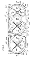
- a dual cup dispenser apparatus of this invention for dispensing two different sizes of cups is designated in its entirety by the reference numeral 1. It comprises a first dispenser 3A for cups of a first size and a second dispenser 3B for cups of either the first or a second size.
- the two dispensers 3A and 3B have a common base, generally designated 5, comprising a generally rectangular plate 7 having downwardly extending side and end flanges 9 and 11 and an assembly of parts on top of the plate forming a compartmented cover structure 13Aforthat portion of the base included in dispenser 3Aand a compartmented cover structure 13B for that portion of the base included in dispenser 3B.
- the first cup dispenser 3A is adapted for dispensing cups 15 each having a rim 17 from a stack of the cups wherein the cups are nested, the cups generally being of a size to be more frequently dispensed.
- the second cup dispenser 3B may hold the same size, or another size.
- the cover structure 13Aand the base plate 7 are made to provide an opening OA (see Figs. 4-6) for the stack of cups to be dispensed.
- This opening has an upper part 21 in the cover structure 13A tapered downwardly and inwardly at its upper end as indicated at 23 for guiding a stack down in the opening, and includes an opening 25 in the base plate 7 with which part 21 registers.
- the opening OA defines a cup dispensing station, also denoted OA, for the dispenser 3A.
- a cup ring 27A is secured to the bottom of the top plate 7 concentric with the opening OA, the opening 29 in the ring registering with the opening OA.
- the cup ring as herein illustrated, is basically similar to the cup ring disclosed in U.S. patent4,426,017 issued January 17, 1989, which is incorporated herein by reference.
- a stack S1 of cups is held up in dispensing position at the dispensing station OA by engagement of the rim 17 of the lowermost cup of the stack with escapement members 19 of the cup ring. These escapement members are rotatable to release the lowermost cup of the stack S1 to drop down away from the base and to hold up the next cup in the stack by its rim and thereby hold up the stack in the dispensing position.
- Rotation of the escapement members 19 is by operation of a lever 37 via gearing of the cup ring mechanism (see Fig 5). Details of the cup ring may be ascertained from the aforesaid U.S. patent4,426,017 and will not be repeated here. It will suffice to say that swinging of the lever in one direction from a retracted position rotates the escapement members in one direction to release the lowermost cup. On return of the lever to its retracted position, the escapement members rotate back to retracted position and the stack S1 drops down in opening OA to the point where the rim of the next cup engages shoulders 61 of members 19, all as disclosed in U.S. patent4,426,017.
- the cup ring is adjustable for holding stacks of cups for different sizes as detailed in said U.S. patent 4,426,017.
- Dispenser 3Afurther comprises means indicated generally at 41 for holding a first set of three reserve stacks RS1, RS2 and RS3 adjacent the dispensing opening OA and means indicated generally at 43 for holding a second set of three reserve stacks RS4, RS5 and RS6, and means indicated generally at 45 operable in response to depletion of the stack S1 in dispensing position in the opening OAformoving a reserve stack of one or the other of the first or second sets into dispensing position with the rim 17 of the lowermost cup of the fresh stack engaging the escapement members 19 of the cup ring 27A.
- the reserve stack RS1 in response to depletion of the stack S1, is advanced one step forward into dispensing position at station OA, and reserve stacks RS2 and RS3 are advanced one step for subsequent delivery to dispensing position.
- the reserve stack RS2 is advanced one step into dispensing position at the dispensing station, and reserve stack RS3 is advanced one step for subsequent transfer to dispensing position.
- the reserve stack RS3 is advanced one step to dispensing position.
- the operation is essentially similar for reserve stacks RS4-RS6.
- the reserve stacks are delivered to dispensing position before the last few cups are dispensed, e.g. when six cups are all that are left.
- Each of the reserve stack holding means 41 and 43 may be referred to as a turret.
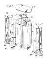
- a housing or canister which is common to the two turrets. This is mounted on top of the base cover structure 13A extending upward therefrom. It has straight side walls 49 and semicircular end walls 51 thereby being generally oval in horizontal cross section.
- Within the canister are curved walls 53 which in conjunction with the end walls define two vertical cylindrical chambers 55 and 57. These are located at diametrically opposite sides of the opening OA. Walls 53 terminate at the opening OA so that each of chambers 55 and 57 is open at the side toward the opening OA.
- the canister is open at the bottom, and has a lid 61.
- a rotary reserve stack pusher means designated in its entirety by the reference character P, one of which is specifically designated P1 and the other P2.
- P rotary reserve stack pusher means
- Each of these may also be referred to as a magazine, since it holds a number of reserve stacks.
- Each resembles a revolving door, comprising a tubular shaft 65 of square cross section journalled at its lower end as indicated at 67 in Fig. 6 in the base and at its upper end as indicated at 69 on a member 69 carried by a bracket 70 mounted at the upper end of the canister, and four vanes or partitions (pushers), each designated 73 extending radially outwardly from the shaft 65 spaced at 90° intervals around the shaft.
- each space constituting a chamber adapted to receive a reserve stack RS of nested cups extending upwardly therein.
- an inclined guide 79 At the lower end of each rotary pusher P in each space 77 is an inclined guide 79.
- Each reserve stack RS of cups extends upwardly in the respective space 77, its lower end being held away from the center shaft 65 by the guide 79 and bearing on the rim of a bottom plate 81 secured on the base centered with respect to the shaft.
- the plate 81 is of circular outline, having a raised rim 83 and a cut-out 85 registering with the opening OA.
- each reserve stack is held in the respective space 77 slightly inclined upwardly and inwardly to minimize its contact with the canister, thereby to minimize friction between the reserve stacks and the canister (see Fig. 3).
- the arrangement is such that on rotation of the pusher 1 to bring each space 77 into registry with the opening OA, the stack in that space is pushed around to drop down out of the space into the opening OAand drops down in OA into the remainder of the stack in OA (e.g. the last sir cups).
- the rim 83 of the plate is formed with guides 83a for guiding the reserve stack into said remainder of the stack in OA.
- Each holder or pusher means P1 ,P2 may be referred to as a magazine since it holds a number, specifically three reserve stacks.
- Each of the rotary pushers P with the partitions 73 spaced at 90° intervals there around is adapted to be indexed in 90° steps successively to bring each space 77(and the reserve stack therein) to the stack drop position generally in register with the opening OA by means comprising an electric motor and a Geneva indexing mechanism driven by this motor.
- the motor for the rotary pusher P1 in chamber 55 is designated MI and the motor for the rotary pusher P2 in chamber 57 is designated M2.
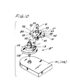
- the Geneva drive mechanism (see Fig. 10) for each rotary pusher is designated in its entirety by the reference numeral 87. It comprises an index wheel 89 having a center stub shaft 91 of square cross section extending up into the lower end of the rotary pusher shaft 65.
- the inder wheel has four radially extending arms 93 spaced at 90° intervals, these arms having arcuate end surfaces 95 on a circle having a diameter 97, and four arcuate recesses each designated 99 in its periphery spaced at 90° intervals. Each arm has a radial groove 101 in the bottom.
- the Geneva mechanism further comprises a drive wheel 103 having a center shaft 105 by means of which it is driven by the motor therefor for rotation on a vertical axis.
- the drive wheel has a portion 109 of circular outline having a recess 111 with a curved base curved on an arc having the same radius as that of the curved end surfaces 95 of the index wheel.
- Wheel 103 has a pin 113 extending upwardly adjacent its periphery in the central vertical plane of the recess 111 in the disk.
- the Geneva drive motor (M1 or M2) rotates the Geneva drive wheel 103 through one revolution on each cycle of operation of the motor and the Geneva drive mechanism.
- the pin 113 enters the groove in one of the arms 93 of the index wheel 89 and rotates the latterthrough one quarter of a revolution (i.e through 90°) thereby to index the respective rotary pusher or magazine P through 90°.
- portion 109 of the drive wheel is initially positioned in a recess 99 in the index wheel, locking the index wheel in position, and rotates around in the recess 99 while the index wheel remains fixed, until the pin 113 enters the groove in one of the arms 93 ofthe index wheel to rotate the index wheel one-quarter turn.
- the cup ring 27A is operated by means indicated generally at 115, comprising a slide bar 117 carried by the base structure for sliding movement relative to the base structure away from and back to a retracted position such as illustrated in Fig. 5, the slide bar being connected to the cup ring lever 37 as indicated at 119.
- the slide bar is biased by a spring 121 to its retracted position and is adapted to be moved away from its retracted position for swinging the cup ring lever 37 to actuate escapement members 19 of the cup ring to release the lowermost cup of the stack in dispensing position by an electric motor M3 driving a crank 123 engaging the slide bar 117 as indicated at 128.
- the arrangement is such that on operation of the motor M3 for one revolution of the crank 123, the slide bar 117 is first moved forward against the bias of spring 121 by the crank away from its retracted position, during a first part of the revolution, and then returned by the spring to retracted position during a second part of the revolution.
- the dispenser 3B corresponds essentially to the dispenser 3A except that it has only one rotary reserve stack pusher P3 corresponding to the pusher P1 and P2 of dispenser 3B, this pusher holding three reserve stacks RS7, RS8 and RS9, and an opening OB and a cup ring 27B corresponding to opening OA and cup ring 27A of dispenser 3A.
- the motor for actuating the cup ring 27B of dispenser 3B is designated M4, and the motor for indexing the reserve stack pusher of dispenser 1B is designated M5.
- the canister and lid for dispenser 3B are designated 47B and 61 B.
- the dispenser 1 is mounted on the inside of the door of the cabinet of a beverage (e.g. coffee) vendor (not shown) with the arrangement such that in dispensing of a cup from either of the two dispensers 3A or 3B the cup is guided to a beverage delivery station in a recess in the door.
- the dispenser 1 may have its base suitably hingedly mounted on the door for being swung out when the door is opened to a position convenient for loading the two reserve stack pushers P1 and P2 of turrets 41 and 43 of dispenser 1Awith reserve stacks RS1-RS6, (dispenser 1A) and for loading the pusher P3 of dispenser 1 B with reserve stacks RS7-RS9.
- Infra red sensors 125A and 125B are provided at stations OA and OB for sensing the depletion of a stack at OA and OB down to a small number, e.g. six, of cups.
- the vendor includes two switches such as indicated at 127 and 129 in Fig. 11, one of which is closed on selection of a vend calling for a first orA size of cup (e.g. an 8-1/4 oz.cup), and the other of which is closed on selection of a vend calling for the second or B size of cup (e.g. a 12 oz.cup).
- switch 129 closes for operation of dispenser 3B in a manner similar to that of dispenser 3A.
- both dispensers 1A and 1B may dispense the same size of cups, e.g. by delivering reserve stacks in the order RS1, RS7, RS2, RS8, RS3, RS9, RS4, RS5 and RS6.
Landscapes
- Physics & Mathematics (AREA)
- General Physics & Mathematics (AREA)
- Beverage Vending Machines With Cups, And Gas Or Electricity Vending Machines (AREA)
- De-Stacking Of Articles (AREA)
Applications Claiming Priority (2)
| Application Number | Priority Date | Filing Date | Title |
|---|---|---|---|
| US07/769,552 US5172828A (en) | 1991-10-01 | 1991-10-01 | Cup dispenser |
| US769552 | 1991-10-01 |
Publications (3)
| Publication Number | Publication Date |
|---|---|
| EP0535855A2 true EP0535855A2 (de) | 1993-04-07 |
| EP0535855A3 EP0535855A3 (de) | 1993-06-16 |
| EP0535855B1 EP0535855B1 (de) | 1996-03-06 |
Family
ID=25085791
Family Applications (1)
| Application Number | Title | Priority Date | Filing Date |
|---|---|---|---|
| EP92308685A Expired - Lifetime EP0535855B1 (de) | 1991-10-01 | 1992-09-24 | Becherabgabevorrichtung |
Country Status (4)
| Country | Link |
|---|---|
| US (1) | US5172828A (de) |
| EP (1) | EP0535855B1 (de) |
| DE (1) | DE69208795T2 (de) |
| SG (1) | SG54216A1 (de) |
Cited By (1)
| Publication number | Priority date | Publication date | Assignee | Title |
|---|---|---|---|---|
| CN109155095A (zh) * | 2016-03-16 | 2019-01-04 | 埃沃咖股份公司 | 饮料自动售货机的杯子分配器 |
Families Citing this family (17)
| Publication number | Priority date | Publication date | Assignee | Title |
|---|---|---|---|---|
| US5605249A (en) * | 1994-12-12 | 1997-02-25 | Gonyea; Gerald | Battery operated vending machine having a carousel stacking arrangement and plunger-type dispenser |
| US6786359B1 (en) | 2001-09-28 | 2004-09-07 | Roy D. Schroeder | Dispenser |
| NL1022294C2 (nl) * | 2002-12-31 | 2004-07-01 | F T T Internat B V | Afgeefinrichting voor bloemenvazen, bloemenvaas en werkwijze voor het in een vaas plaatsen van bloemen. |
| US7270248B2 (en) * | 2003-11-03 | 2007-09-18 | Schroeder Roy D | Adjustable dispenser for soft pliable lids |
| JP3971375B2 (ja) * | 2003-12-26 | 2007-09-05 | 株式会社コナミデジタルエンタテインメント | 自動販売機 |
| US7431176B2 (en) * | 2005-06-17 | 2008-10-07 | Barryco Technologies Inc. | Dispensing machine to store and dispense elongated containers vertically |
| PL2369559T3 (pl) * | 2010-03-11 | 2017-05-31 | Rheavendors Services S.P.A. | Automat towarowy i sposób dozowania napojów |
| AU2011246922B2 (en) * | 2010-04-26 | 2015-05-14 | Saga Coffee S.P.A. | A stirrer or spoon dispenser for beverage dispensing machines |
| US9038853B2 (en) * | 2011-08-26 | 2015-05-26 | Kil Jae Chang | Sanitized vending machine and method |
| CA2846821A1 (en) * | 2011-08-26 | 2013-03-07 | Crane Merchandising Systems, Inc. | Planetary gear drive cup turret for cup drop unit in beverage vending machine |
| DE202011105477U1 (de) * | 2011-09-08 | 2012-02-07 | Sielaff Gmbh & Co. Kg Automatenbau | Automat zur Zubereitung und Ausgabe eines Getränks |
| US8727178B1 (en) * | 2011-11-20 | 2014-05-20 | Irene Carter | Condiment packet dispenser |
| US9489791B2 (en) * | 2012-07-30 | 2016-11-08 | Kil Jae Chang | Sanitized vending machine having cup retention-and-release mechanism |
| US9384621B1 (en) * | 2012-07-30 | 2016-07-05 | Kil Jae Chang | Product and cup dispensing mechanisms concentrically arranged on common rotatable wheel in a sanitized vending machine |
| CN205575600U (zh) * | 2015-09-21 | 2016-09-14 | 上海巨昂实业有限公司 | 一种包括自动门板的榨汁机自动包装装置 |
| DE102020204364A1 (de) | 2020-04-03 | 2021-10-07 | Sielaff GmbH & Co. KG Automatenbau Herrieden | Automat und verfahren zum zubereiten und ausgeben eines getränks |
| EP4277863A4 (de) * | 2021-01-17 | 2024-12-18 | Aquabot Ltd. | Produktauswahlsystem |
Family Cites Families (7)
| Publication number | Priority date | Publication date | Assignee | Title |
|---|---|---|---|---|
| US2394262A (en) * | 1943-10-09 | 1946-02-05 | Lily Tulip Cup Corp | Multistack nested article dispensing apparatus |
| US3283951A (en) * | 1964-05-25 | 1966-11-08 | Alan D Gladfelder | Cup dispenser |
| DE1801185B2 (de) * | 1968-10-04 | 1971-09-02 | Kückens, Alexander, 2000 Hamburg | Vorrichtung zur beschleunigten ausgabe von bechern aus becher oder getraenkeautomaten |
| US3807600A (en) * | 1972-09-27 | 1974-04-30 | Vendo Co | Cup dispensing apparatus |
| CA1220457A (en) * | 1983-08-03 | 1987-04-14 | Manfred Garbe | Beverage dispenser and dispensing process |
| KR910005956B1 (ko) * | 1988-11-14 | 1991-08-09 | 삼성전자 주식회사 | 자동 판매기의 보조컵적재대를 갖는 컵디스펜서 및 그 제어 회로 |
| US4989753A (en) * | 1989-05-18 | 1991-02-05 | Pepsico Inc. | Cup dispenser for an automated drinkmaker system |
-
1991
- 1991-10-01 US US07/769,552 patent/US5172828A/en not_active Expired - Lifetime
-
1992
- 1992-09-24 DE DE69208795T patent/DE69208795T2/de not_active Expired - Lifetime
- 1992-09-24 SG SG1996004569A patent/SG54216A1/en unknown
- 1992-09-24 EP EP92308685A patent/EP0535855B1/de not_active Expired - Lifetime
Non-Patent Citations (1)
| Title |
|---|
| None |
Cited By (1)
| Publication number | Priority date | Publication date | Assignee | Title |
|---|---|---|---|---|
| CN109155095A (zh) * | 2016-03-16 | 2019-01-04 | 埃沃咖股份公司 | 饮料自动售货机的杯子分配器 |
Also Published As
| Publication number | Publication date |
|---|---|
| DE69208795T2 (de) | 1996-09-19 |
| DE69208795D1 (de) | 1996-04-11 |
| SG54216A1 (en) | 1998-11-16 |
| EP0535855B1 (de) | 1996-03-06 |
| EP0535855A3 (de) | 1993-06-16 |
| US5172828A (en) | 1992-12-22 |
Similar Documents
| Publication | Publication Date | Title |
|---|---|---|
| US5172828A (en) | Cup dispenser | |
| EP0166832B1 (de) | Becherabgabevorrichtung | |
| EP0719537B1 (de) | Abfüllgerät für Medikamente | |
| CA1040443A (en) | Ice cream dispensing machine | |
| EP0577293B1 (de) | Verfahren und Einrichtung zur Ausgabe von Bechern in Getränkeverkaufautomaten | |
| JPS5837199B2 (ja) | コップ積重体からコップを選択的に取り出す装置 | |
| CA1053194A (en) | Article vending machine | |
| US3807600A (en) | Cup dispensing apparatus | |
| US6378724B1 (en) | Machine and method for vending products one at a time from lower ends of circular row of columns | |
| EP0257751B1 (de) | Getränkeverkaufsautomat | |
| US4195751A (en) | Cup selection apparatus for beverage vending machine to the in-cup type | |
| WO2002025607A1 (en) | Machine with enhanced features for reliably vending products one at a time | |
| US4635816A (en) | Vending machine delivering cups containing freshly made beverages | |
| GB1604306A (en) | Beverage dispensing machines | |
| US2925196A (en) | Cup dispensing mechanism | |
| US2423265A (en) | Vending machine | |
| GB2090821A (en) | Vending apparatus | |
| US3698601A (en) | Magazine for dispensing machine | |
| US4429807A (en) | Adjustable dispensing mechanism for vending machine | |
| US4580697A (en) | Cup drop ring for drink machine | |
| EP0084695A1 (de) | Beweglicher Auswahlförderer | |
| US3576275A (en) | Cup-handling mechanism | |
| US3300086A (en) | Vending machine with coordinated package holders | |
| US3311260A (en) | Cup dispensing apparatus | |
| US4351452A (en) | Turret cup supply and delivery apparatus |
Legal Events
| Date | Code | Title | Description |
|---|---|---|---|
| PUAI | Public reference made under article 153(3) epc to a published international application that has entered the european phase |
Free format text: ORIGINAL CODE: 0009012 |
|
| AK | Designated contracting states |
Kind code of ref document: A2 Designated state(s): DE FR GB IT |
|
| PUAL | Search report despatched |
Free format text: ORIGINAL CODE: 0009013 |
|
| AK | Designated contracting states |
Kind code of ref document: A3 Designated state(s): DE FR GB IT |
|
| RIN1 | Information on inventor provided before grant (corrected) |
Inventor name: PODGORNY, GERALD J. CRANE NATIONAL VENDORS Inventor name: FICKEN, LEONARD A. CRANE NATIONAL VENDORS |
|
| 17P | Request for examination filed |
Effective date: 19930819 |
|
| 17Q | First examination report despatched |
Effective date: 19941207 |
|
| GRAH | Despatch of communication of intention to grant a patent |
Free format text: ORIGINAL CODE: EPIDOS IGRA |
|
| GRAA | (expected) grant |
Free format text: ORIGINAL CODE: 0009210 |
|
| AK | Designated contracting states |
Kind code of ref document: B1 Designated state(s): DE FR GB IT |
|
| REF | Corresponds to: |
Ref document number: 69208795 Country of ref document: DE Date of ref document: 19960411 |
|
| ITF | It: translation for a ep patent filed | ||
| ET | Fr: translation filed | ||
| PLBE | No opposition filed within time limit |
Free format text: ORIGINAL CODE: 0009261 |
|
| 26N | No opposition filed | ||
| PGFP | Annual fee paid to national office [announced via postgrant information from national office to epo] |
Ref country code: FR Payment date: 20000912 Year of fee payment: 9 |
|
| REG | Reference to a national code |
Ref country code: GB Ref legal event code: IF02 |
|
| PG25 | Lapsed in a contracting state [announced via postgrant information from national office to epo] |
Ref country code: FR Free format text: LAPSE BECAUSE OF NON-PAYMENT OF DUE FEES Effective date: 20020531 |
|
| REG | Reference to a national code |
Ref country code: FR Ref legal event code: ST |
|
| PGFP | Annual fee paid to national office [announced via postgrant information from national office to epo] |
Ref country code: IT Payment date: 20100925 Year of fee payment: 19 |
|
| PGFP | Annual fee paid to national office [announced via postgrant information from national office to epo] |
Ref country code: DE Payment date: 20100929 Year of fee payment: 19 |
|
| PGFP | Annual fee paid to national office [announced via postgrant information from national office to epo] |
Ref country code: GB Payment date: 20110928 Year of fee payment: 20 |
|
| REG | Reference to a national code |
Ref country code: DE Ref legal event code: R082 Ref document number: 69208795 Country of ref document: DE Representative=s name: W.P.THOMPSON & CO., GB |
|
| REG | Reference to a national code |
Ref country code: DE Ref legal event code: R071 Ref document number: 69208795 Country of ref document: DE |
|
| REG | Reference to a national code |
Ref country code: DE Ref legal event code: R071 Ref document number: 69208795 Country of ref document: DE |
|
| REG | Reference to a national code |
Ref country code: GB Ref legal event code: PE20 Expiry date: 20120923 |
|
| PG25 | Lapsed in a contracting state [announced via postgrant information from national office to epo] |
Ref country code: GB Free format text: LAPSE BECAUSE OF EXPIRATION OF PROTECTION Effective date: 20120923 Ref country code: DE Free format text: LAPSE BECAUSE OF EXPIRATION OF PROTECTION Effective date: 20120925 |