EP0535936A2 - Appareil et méthode magnéto-résistifs pour la lecture de caractères à encre magnétique - Google Patents
Appareil et méthode magnéto-résistifs pour la lecture de caractères à encre magnétique Download PDFInfo
- Publication number
- EP0535936A2 EP0535936A2 EP92308920A EP92308920A EP0535936A2 EP 0535936 A2 EP0535936 A2 EP 0535936A2 EP 92308920 A EP92308920 A EP 92308920A EP 92308920 A EP92308920 A EP 92308920A EP 0535936 A2 EP0535936 A2 EP 0535936A2
- Authority
- EP
- European Patent Office
- Prior art keywords
- sensors
- magnetoresistive
- width
- read head
- read
- Prior art date
- Legal status (The legal status is an assumption and is not a legal conclusion. Google has not performed a legal analysis and makes no representation as to the accuracy of the status listed.)
- Granted
Links
Images




Classifications
-
- G—PHYSICS
- G06—COMPUTING OR CALCULATING; COUNTING
- G06K—GRAPHICAL DATA READING; PRESENTATION OF DATA; RECORD CARRIERS; HANDLING RECORD CARRIERS
- G06K7/00—Methods or arrangements for sensing record carriers, e.g. for reading patterns
- G06K7/08—Methods or arrangements for sensing record carriers, e.g. for reading patterns by means detecting the change of an electrostatic or magnetic field, e.g. by detecting change of capacitance between electrodes
- G06K7/082—Methods or arrangements for sensing record carriers, e.g. for reading patterns by means detecting the change of an electrostatic or magnetic field, e.g. by detecting change of capacitance between electrodes using inductive or magnetic sensors
- G06K7/087—Methods or arrangements for sensing record carriers, e.g. for reading patterns by means detecting the change of an electrostatic or magnetic field, e.g. by detecting change of capacitance between electrodes using inductive or magnetic sensors flux-sensitive, e.g. magnetic, detectors
Definitions
- the present invention relates to a magnetic-ink-character reading apparatus and method.
- MICR characters or those printed on documents in magnetic ink according to EI3B and CMC 7 fonts have a magnetic field strength which is extremely weak.
- a poorly printed single printed bar in the CMC 7 font or coding, for example, may have a magnetic field strength of approximately 0.06 Gauss. Such a weak magnetic field strength can be detected reliably only through using a read head which employs inductive technology.
- magnetoresistive magnetic-ink-character reading apparatus characterized by a read head comprising a substrate having first and second magnetoresistive sensors thereon, said sensors being in the form of parallel strips spaced apart in a side by side relationship, and coupling means coupling said first and second magnetoresistive sensors into a read circuit.
- the present invention advantageously provides for a read head which is manufactured as a thin film device, making the read head inexpensive to manufacture and small in size.
- the signal strength or output of the read head is independent of the relative velocity between the characters on the document and the read head.
- a method of reading magnetic ink characters characterized by passing a read head comprising a substrate supporting first and second magnetoresistive sensors in the form of parallel strips space apart in a side by side relationship past said characters the combined width of said two strips and the spacing therebetween being equal or less than the width of a single bar of a character.
- Fig. 1 is a schematic diagram showing an apparatus 10 in which a read head made according to this invention may be used.
- the apparatus 10 includes a document track 14 which receives a document 16 to be read.
- the document 16 has a MICR band or zone 16-1 near the bottom of the document 16, as viewed in Fig. 1, with the MICR characters 16-2 to be read being located in the zone 16-1.
- the apparatus 10 also includes a document transport 18 which moves the document 16 to be read past a write head 20 to magnetize the magnetic ink on the document for the characters to be read.
- the document transport 18 then moves the document 16 in operative relationship with a read head 22 which is the subject of this invention.
- the output of the read head 22 is directed to a read circuit 24 whose output is fed to a controller 26.
- Fig. 2 shows a character 28 which is a "0" or zero printed in CMC 7 font
- Fig. 3 shows the associated wave form 30 which results when the character28 is moved relative to the read head 22.
- Fig. 4 shows a character 32 which is a "1" printed in the CMC 7 font
- Fig. 5 shows the associated wave form 34.
- Fig. 6 shows a character 36 which is a "0" or zero printed in EI3B font
- Fig. 7 shows the associated wave form 38 which results when the character 28 is moved relative to the read head 22.
- Fig. 2 shows a character 28 which is a "0" or zero printed in CMC 7 font
- Fig. 3 shows the associated wave form 30 which results when the character28 is moved relative to the read head 22.
- Fig. 4 shows a character 32 which is a "1" printed in the CMC 7 font
- Fig. 5 shows the associated wave form 34.
- Fig. 6 shows a character 36 which is a "0" or zero
- FIG. 8 shows a character 40 which is a "1" printed in the EI3B font
- Fig. 9 shows the associated wave form 42. While this invention is described in relation to these two fonts, the principles of this invention may be extended to other characters or data printed in magnetic ink.
- the read head 22 shown in Fig. 1 is shown in more detail in Figs. 10 and 11.
- the read head 22 includes first and second magnetoresistive elements 22-1 and 22-2 which are located or deposited on a silicon substrate 22-3 (Fig. 11) and mounted on a base 22-31, like glass. Connection means, like terminal pins 22-4 and 22-5, are used to couple the first magnetoresistive element 22-1 to an outside circuit, and similarly, terminal pins 22-6 and 22-7 are used to couple the second magnetoresistive element 22-2 to an outside circuit.
- the first and second magnetoresistive elements 22-1 and 22-2 are made of NiFe Permalloy and are deposited on the substrate 22-3 and mounted on the glass base 22-31.
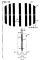
- Fig. 10 The relationship of the print head 22 to the MICR character to be read is shown best in Fig. 10.
- the top portion of Fig. 10 shows the character 28 which is a "0" as printed in CMC 7 font as discussed in relation to Fig. 2.
- the character 28 is enlarged in general and compressed in the vertical direction in Fig. 10; however, the width of the bars and spaces which make up the character are shown in the correct scale relative to the width of the first and second magnetoresistive elements 22-1 and 22-2 also shown in Fig. 10.
- the gap or distance between the magnetoresistive elements 22-1 and 22-2 is G1.
- W3 The width of all the bars, like 28-1, of a character in CMC 7 encoding or font is equal to W3, and this particular font has two different spacings between the bars.
- W3, W4, and W5, in various combinations, are dictated by the particular font used.
- W is equal to W1 + W2 + G1 or2W1 + G1.
- the above parameters provide for optimum performance of the read head 22 even on a worst case basis, as for example, for a situation in which, for a character, the bar width is a maximum and the space between the bars is at a minimum in CMC 7 font.
- the width (W3) of a bar, like 28-1 in Fig. 10, is equal to 0.006 inch (0.15mm), and the width of the narrow spacing (W4) is also 0.006 inch (0.15mm). Notice that the total width W (0.0029) (73.66 f..lm) of the read head 22 is less than the width W3 (0.006) (0.15mm) of a bar 28-1 in the CMC 7 font; this is shown in Fig. 10.
- Fig. 12 shows a prior art read head 44 having a width of about 0.010 inch (0.25mm); notice that this width is greater than the width of a bar, like 28-1, of a character 28.
- the resulting magnetic waveform 46 was not able to distinguish between the two bars 28-1 and 28-2 making up the portion of the character shown.
- a magnetic waveform 48 (Fig. 13) is generated, with the waveform 48 being positioned below waveform 46 to show the comparison when reading the same portion of the character 28.
- the width (W) of the read head 22 (Fig. 10) is less than the width of a bar 28-1 in the CMC 7 font.
- One of the problems with prior art readers was that they were not able to get the sensitivity required to read the low level signals which are provided by the MICR characters on a document or check.
- the magnetoresistive elements 22-1 and 22-2 of the read head 22 are made of nickel-iron permalloy and deposited on the substrate 22-3 as discussed in relation to Fig. 11.
- the total resistance of each magnetoresistive element 22-1 and 22-2 is 1.6K ohms.
- Another important feature is that when making the magnetoresistive elements 22-1 and 22-2, the maximum magnetic field that an element will be exposed to is about 200 gauss in one embodiment.
- One of the problems with readers of the type being described is that if the magnetoresistive elements are subjected to a high density field, these magnetoresistive elements will produce a reading; however, they will retain the changed resistance for a long time before returning to the initial state. This is why a field strength maximum is designated. If the read head 22 is to be used in an environment which has a high magnetic field, sufficient magnetic shielding should be provided to avoid the maximum magnetic field mentioned.
- Fig. 14 is a schematic diagram of the read circuit 24 shown only generally in Fig. 1.
- magnetoresistive elements MR1 and MR2, shown in Fig. 14, correspond to the first and second magnetoresistive sensing elements 22-1 and 22-2 shown in Fig. 10, for example.
- magnetoresistive element MR2 When a document 16 is moved to the right by the document transport shown in Fig. 1, it is the magnetoresistive element MR2 which is first encountered by the MICR characters on the document 16.
- magnetoresistive elements MR1 and MR2 each have a resistance of 1.6K ohms, and resistors R1 and R2 each have a resistance of 1.6 K ohms.
- the resistors R1 and R2 are shown in dashed outline in Figs. 10 and 11.
- the operation of the read circuit 24 (Fig. 14) is as follows. When there is no document 16 or no motion of a document 16 in front of the read head 22, the voltage at nodes 50 and 52 is 2.5 volts for the circuit shown. Nodes 50 and 52 are coupled to the (+) and (-) inputs of a differential amplifier 54 through capacitors C1 and C2 as shown. With nodes 50 and 52 at 2.5 volts, the output from the differential amplifier 54 is 0 volts.
- the read circuit 24 has the general configuration of a full bridge circuit whereas the prior art circuits are generally half bridge circuits for coupling a single sensing element as discussed in relation to Fig. 12.
- the MICR characters are magnetically activated by the write head 20 as is customarily done. Thereafter, the document 16 is moved into operative relationship with the read head 22 (as viewed in Fig. 1), and the magnetoresistive element MR2 is the first one which will encounter the MICR data on the document 16.
- the magnetoresistive element MR2 is the first one which will encounter the MICR data on the document 16.
- the resistance of this element is increased, making the voltage level at node 52 decrease below the 2.5 V level which occurs when no document is present in the example being described. Because of this difference in voltage between nodes 50 and 52, there will be an output from the differential amplifier 54.
- the lines of flux from the MICR character which influenced the magnetoresistive element MR2 will then influence the magnetoresistive element MR1.
- the lines offluxwhich influence the magnetoresistive element MR2 are the same which influence the magnetoresistive element MR1, although they are not always the same.
- the lines of flux hit the magnetoresistive element MR1 its resistance tends to rise, making the voltage at node 50 fall.
- the voltage level at node 52 has fallen, and shortly thereafter, the voltage level at node 50 also falls, it means that there is little, if any, voltage differential between the nodes 50 and 52. Consequently, it means that there is very little output from the differential amplifier 54.
- Increasing the output from a read head can advantageously be achieved as follows.
- Fig. 15 is a second embodiment of the read circuit 24 shown in Fig, 1, with the second embodiment being referred to as circuit 24-2.
- the circuit 24-2 contains the same components as discussed in relation to Fig. 14; however, they are arranged to provide a greater signal strength from the read head 22 than does the read circuit 24.
- the positions of the magnetoresistive element MR1 and its associated resistor are reversed as shown in Fig. 15. Assuming the same physical layout for the read head 22, essentially the same magnetic lines of force will be in flux coupling relationship with the magnetoresistive element MR 2 first, and shortly thereafter, the magnetic lines of force will encounter the magnetoresistive element MR1.
- the voltage at node 52 falls as previously discussed, and when the lines of force encounter the magnetoresistive element MR1, the voltage at node 50 rises.
- the voltage at node 52 (Fig. 15) falls to from 2.5 volts to about 2 volts, and the voltage at node 50 rises from 2.5 volts to about 3 volts, there will be a voltage differential of one volt supplied to the operational amplifier 54.
- the read circuit 24-2 (Fig. 15) is two times more sensitive than the read circuit 24 shown in Fig. 14.
- the changes in voltage at the nodes 50 and 52 amount to about 100 microvolts.
- the resistors R1 and R2 which appear in the circuits 24 and 24-2 tend to heat in use, and there is a thermal coefficient associated with them.
- the capacitors C1 and C2 are there for the purpose of screening out slow DC changes which occur when these resistors R1 and R2 just sit there with current passing through them. In other words, the AC changes which occur when a character on a document passes the read head 22 are the sought-after changes.
- the voltage level at node 52 changes from V/2 to (V/2 - e l ).
- the voltage level at node 50 changes from V/2 to (V/2 + e l ).
- the values e l and e l represent the voltage changes at the nodes 52 and 50.
- the differential amplifier 54 shown in Figs. 14, 15, and 16, provides a gain of 180 at node 56 (Fig. 16) in the embodiments described.
- the signal level from the read circuit24-2 is twice that of the read circuit 24.
- An operational or op amplifier 58 provides an additional gain of 10. The output of the op amplifier 58 is fed into the controller 26 for further processing which is not important to an understanding of this invention.
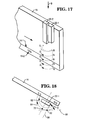
- Fig. 17 shows the magnetoresistive elements 22-1 and 22-2 as they are positioned relative to the face of the document 16 to read the magnetic waveshapes associated with the MICR characters 16-2.
- R o Isotropic resistance (values are the same at all angles of measurement);
- Theta Angle between the current and the magnetization.
- Fig. 17 shows the first and second magnetoresistive elements 22-1 and 22-2 as they appear in operative relationship with the MICR characters 16-2 appearing on the face of the document 16.
- Fig. 18 shows the magnetic fields, like magnetization lines 62 and 64, as they are in operative relationship with the first magnetoresistive element 22-1.
- the angle Theta referred to in the above equation, is shown in Fig. 18, and its vertex like point 60 is tangent to the magnetization lines shown as lines 64.
- One side of the angle Theta is formed by a line 66 which is perpendicular to the magnetoresistive element 22-1 and passes through the point 60, and the other side, like line 68, is tangent to the magnetic lines of force 64 at the point 60.
- the magnetoresistive element 22-1 produces the maximum signal level when the associated angle Theta is equal to zero which occurs at point 70 in Fig. 18.
- the cosine of 0 degrees is equal to "1" which means that the resistance R of the magnetoresistive element 22-1 is equal to its isotropic resistance R o .
- the angle Theta is 180 degrees, the associated cosine is equal to -1. From the above equation, the resistance R of the magnetoresistive element 22-1 is less than its resistance R o .
- Another feature of the present invention compared to the inductive technology mentioned earlier herein relates to the spacing between the document being read and the surface of the associated read head.
- the maximum space permissible between the document being read and the surface of the read head itself for the inductive technology mentioned is about .001 inch (25.4 ⁇ m).
- Sometimes a signal can be detected when the spacing is about .002 inch (50.8 pm); however, the signal received cannot be relied upon as being accurate.
- the read head 22 of the present invention the document being read can be spaced from the surface of the read head 22 by about .008 inch (0.20mm) and still provide a viable reading. This feature makes the cost of the read head 22 cheaper than the inductive type read head, and it also subjects the read head 22 to less wear when compared to an inductive read head.
- the read head 22 is not velocity dependent as is the case with the inductive read head.
- the document 16 can be moved past the read head 22 at speeds ranging from practically zero to 1,000 inches (25.4m) per second.
- the actual upper limit has not been determined as yet.
- the maximum signal frequency for CMC 7 encoding works out to be about 7 KH. If the document speed is increased to 200 inches (5.08m) per second, the maximum signal frequency becomes 14 KH, etc.
- the frequency response for EI3B is less than that for CMC 7. If the document speed were increased to 1000 inches (25.4m) per second, the maximum signal frequency would be 70 KH.
- the maximum signal response would be 210 KH.
- the maximum frequency response forthe system 10 is about 200 KH, so close to 3000 inches (76.2m) per second would appear to be the limit for the system 10.
- the point to be made is that it is just about impossible to drive a document at 1000 inches (25.4m) per second; in fact, just about 400 inches (10.16m) per second appears to be the maximum speed for moving a document in a controlled manner.
Landscapes
- Engineering & Computer Science (AREA)
- Artificial Intelligence (AREA)
- Computer Vision & Pattern Recognition (AREA)
- Physics & Mathematics (AREA)
- General Physics & Mathematics (AREA)
- Theoretical Computer Science (AREA)
- Character Input (AREA)
- Magnetic Heads (AREA)
- Character Discrimination (AREA)
Applications Claiming Priority (2)
| Application Number | Priority Date | Filing Date | Title |
|---|---|---|---|
| US769909 | 1991-10-01 | ||
| US07/769,909 US5266786A (en) | 1991-10-01 | 1991-10-01 | Magnetoresistive head for reading magnetic ink characters |
Publications (3)
| Publication Number | Publication Date |
|---|---|
| EP0535936A2 true EP0535936A2 (fr) | 1993-04-07 |
| EP0535936A3 EP0535936A3 (fr) | 1994-10-12 |
| EP0535936B1 EP0535936B1 (fr) | 1997-12-29 |
Family
ID=25086869
Family Applications (1)
| Application Number | Title | Priority Date | Filing Date |
|---|---|---|---|
| EP92308920A Expired - Lifetime EP0535936B1 (fr) | 1991-10-01 | 1992-09-30 | Appareil magnéto-résistif et méthode pour la lecture de caractères à encre magnétique |
Country Status (5)
| Country | Link |
|---|---|
| US (1) | US5266786A (fr) |
| EP (1) | EP0535936B1 (fr) |
| JP (1) | JP3377539B2 (fr) |
| CA (1) | CA2079566C (fr) |
| DE (1) | DE69223721T2 (fr) |
Cited By (3)
| Publication number | Priority date | Publication date | Assignee | Title |
|---|---|---|---|---|
| FR2742898A1 (fr) * | 1995-12-22 | 1997-06-27 | Tenenbaum Jean | Dispositif de lecture de caracteres magnetisables |
| EP0780837A3 (fr) * | 1995-12-19 | 2000-08-30 | Canon Denshi Kabushiki Kaisha | Support d'enregistrement sur lequel l'information est enregistré par façon intermittante et procédé et appareil de reproduction d'information |
| DE19800805B4 (de) * | 1998-01-12 | 2006-12-14 | Siemens Ag | Verfahren und Sensoranordnung zur Generierung eines Referenzsignals |
Families Citing this family (12)
| Publication number | Priority date | Publication date | Assignee | Title |
|---|---|---|---|---|
| JP3983312B2 (ja) * | 1995-01-12 | 2007-09-26 | ゼロックス コーポレイション | プリンタのセキュリティモジュール |
| US5613783A (en) * | 1995-03-27 | 1997-03-25 | International Business Machines Corporation | Point of sale printer with magnetic reader |
| US5650606A (en) * | 1995-08-07 | 1997-07-22 | Magnetic Products International, Corp | Accurate read/write head for preventing credit card alteration and counterfeiting of debit cards |
| US5729621A (en) * | 1995-08-31 | 1998-03-17 | Ncr Corporation | Method and apparatus for magnetic ink character recognition using a magneto-resistive read head |
| US5701222A (en) * | 1995-09-11 | 1997-12-23 | International Business Machines Corporation | Spin valve sensor with antiparallel magnetization of pinned layers |
| US6473519B1 (en) | 1996-02-21 | 2002-10-29 | Hand Held Products, Inc. | Check reader |
| FR2757986A1 (fr) * | 1996-12-31 | 1998-07-03 | Philips Electronics Nv | Systeme de lecture d'informations magnetiques integre |
| JP4617537B2 (ja) * | 2000-06-06 | 2011-01-26 | セイコーエプソン株式会社 | 磁気パターンの認識方法、情報記録媒体、磁気パターン認識装置及び複合処理装置 |
| US7762380B2 (en) * | 2006-03-09 | 2010-07-27 | Cummins-Allison Corp. | Currency discrimination system and method |
| DE102011110138A1 (de) | 2011-08-15 | 2013-02-21 | Meas Deutschland Gmbh | Messvorrichtung zum Messen magnetischer Eigenschaften der Umgebung der Messvorrichtung |
| JP2016189055A (ja) * | 2015-03-30 | 2016-11-04 | 日本電産サンキョー株式会社 | カードリーダ |
| US20200108649A1 (en) * | 2018-10-09 | 2020-04-09 | Toshiba Tec Kabushiki Kaisha | Reading apparatus, printer, and information processing method |
Family Cites Families (19)
| Publication number | Priority date | Publication date | Assignee | Title |
|---|---|---|---|---|
| US3796859A (en) * | 1971-12-27 | 1974-03-12 | Ibm | Magnetic ink recording system to both magnetize and read ink |
| US3814863A (en) * | 1972-10-11 | 1974-06-04 | Ibm | Internally biased magnetoresistive magnetic transducer |
| US3813692A (en) * | 1972-10-11 | 1974-05-28 | Ibm | Internally biased magnetoresistive magnetic transducer |
| US3840898A (en) * | 1972-12-29 | 1974-10-08 | Ibm | Self-biased magnetoresistive sensor |
| US3860965A (en) * | 1973-10-04 | 1975-01-14 | Ibm | Magnetoresistive read head assembly having matched elements for common mode rejection |
| US3921218A (en) * | 1973-12-26 | 1975-11-18 | Honeywell Inf Systems | Thin film magnetoresistive transducers with rotated magnetic easy axis |
| FR2389180A1 (fr) * | 1977-04-29 | 1978-11-24 | Cii Honeywell Bull | Dispositif de transduction magnetique de detection d'informations magnetiques codees et procede de fabrication dudit dispositif |
| FR2390778A1 (fr) * | 1977-05-13 | 1978-12-08 | Cii Honeywell Bull | Dispositif de lecture d'informations magnetiques |
| FR2402252A1 (fr) * | 1977-08-30 | 1979-03-30 | Cii Honeywell Bull | Dispositif de lecture de caracteres imprimes |
| US4703378A (en) * | 1984-03-01 | 1987-10-27 | Sony Corporation | Magnetic transducer head utilizing magnetoresistance effect |
| US4623867A (en) * | 1984-08-13 | 1986-11-18 | Ampex Corporation | Permanent magnet biased narrow track magnetoresistive transducer |
| JPS61214205A (ja) * | 1985-03-20 | 1986-09-24 | Sony Corp | ヨ−ク型磁気抵抗効果型磁気ヘツド |
| JPS6234316A (ja) * | 1985-08-07 | 1987-02-14 | Victor Co Of Japan Ltd | 磁気抵抗効果素子を用いた磁気ヘツド、及びその製作法 |
| JPS62184616A (ja) * | 1986-02-10 | 1987-08-13 | Hitachi Ltd | 磁気抵抗効果型磁気ヘツド |
| US4928188A (en) * | 1988-07-05 | 1990-05-22 | Eastman Kodak Company | Magnetoresistive element sandwiched between a sal ferrite substrateand a cover containing an easy axis biasing magnet |
| US4903158A (en) * | 1988-07-28 | 1990-02-20 | Eastman Kodak Company | MR head with complementary easy axis permanent magnet |
| US4899240A (en) * | 1988-07-28 | 1990-02-06 | Eastman Kodak Company | Biasing for a UMR head |
| US5084794A (en) * | 1990-03-29 | 1992-01-28 | Eastman Kodak Company | Shorted dual element magnetoresistive reproduce head exhibiting high density signal amplification |
| US5155643A (en) * | 1990-10-30 | 1992-10-13 | Mars Incorporated | Unshielded horizontal magnetoresistive head and method of fabricating same |
-
1991
- 1991-10-01 US US07/769,909 patent/US5266786A/en not_active Expired - Fee Related
-
1992
- 1992-09-30 CA CA002079566A patent/CA2079566C/fr not_active Expired - Fee Related
- 1992-09-30 JP JP28345992A patent/JP3377539B2/ja not_active Expired - Fee Related
- 1992-09-30 DE DE69223721T patent/DE69223721T2/de not_active Expired - Fee Related
- 1992-09-30 EP EP92308920A patent/EP0535936B1/fr not_active Expired - Lifetime
Cited By (4)
| Publication number | Priority date | Publication date | Assignee | Title |
|---|---|---|---|---|
| EP0780837A3 (fr) * | 1995-12-19 | 2000-08-30 | Canon Denshi Kabushiki Kaisha | Support d'enregistrement sur lequel l'information est enregistré par façon intermittante et procédé et appareil de reproduction d'information |
| FR2742898A1 (fr) * | 1995-12-22 | 1997-06-27 | Tenenbaum Jean | Dispositif de lecture de caracteres magnetisables |
| WO1997023841A1 (fr) * | 1995-12-22 | 1997-07-03 | Jean Tenenbaum | Dispositif de lecture de caracteres magnetisables |
| DE19800805B4 (de) * | 1998-01-12 | 2006-12-14 | Siemens Ag | Verfahren und Sensoranordnung zur Generierung eines Referenzsignals |
Also Published As
| Publication number | Publication date |
|---|---|
| CA2079566C (fr) | 1998-04-21 |
| US5266786A (en) | 1993-11-30 |
| EP0535936A3 (fr) | 1994-10-12 |
| JP3377539B2 (ja) | 2003-02-17 |
| JPH05314313A (ja) | 1993-11-26 |
| CA2079566A1 (fr) | 1993-04-02 |
| DE69223721D1 (de) | 1998-02-05 |
| DE69223721T2 (de) | 1998-07-30 |
| EP0535936B1 (fr) | 1997-12-29 |
Similar Documents
| Publication | Publication Date | Title |
|---|---|---|
| EP0535936B1 (fr) | Appareil magnéto-résistif et méthode pour la lecture de caractères à encre magnétique | |
| US4535375A (en) | Magnetoresistive head | |
| US5357388A (en) | Shorted dual element magnetoresistive reproduce head exhibiting high density signal amplification | |
| JP3244503B2 (ja) | シールドされていない水平型磁気抵抗ヘッド及びその製作方法 | |
| EP0801380A2 (fr) | Transducteurs à effet magnétorésistif géant avec un signal de sortie augmenté | |
| US4566050A (en) | Skew insensitive magnetic read head | |
| EP0216062A1 (fr) | Assemblage de transducteur de lecture magnétorésistif | |
| EP0215270A1 (fr) | Procédé et appareil de lecture au moyen d'une tête magnétorésistive de données enregistrées | |
| JP3206810B2 (ja) | 磁気検出装置 | |
| JPH0439738B2 (fr) | ||
| EP0605336B1 (fr) | Détecteur magnétorésistif de champ magnétique ayant une région active très longue | |
| BE1005586A0 (nl) | Optekeninrichting voorzien van een temperatuurafhankelijke schrijfstroomregeling. | |
| US5378885A (en) | Unshielded magnetoresistive head with multiple pairs of sensing elements | |
| US4212041A (en) | Apparatus and method for removing the effect of interference magnetic fields in a magnetic transducer device for detecting information magnetically coded on a carrier | |
| EP0101825A1 (fr) | Transducteur magnétique résistant pour données enregistrées verticalement et procédé pour convertir de telles données | |
| US6073845A (en) | Recording medium on which information is recorded in intermittent pattern, and method of and apparatus for reproducing the information | |
| US4246474A (en) | Method and apparatus for reading magnetically coded data | |
| JPH0337122Y2 (fr) | ||
| CA1325846C (fr) | Dispositif de lecture d'informations a tete magnetique | |
| Bajorek et al. | Hand-held magnetoresistive transducer | |
| US4097910A (en) | Single gap magnetic read head | |
| US4184631A (en) | Device for reading information magnetically coded on a carrier | |
| US4580175A (en) | Endless, folded magnetoresistive head | |
| EP0668511A2 (fr) | Appareil ou méthode pour capter un champ magnétique; capteur pour lire de l'information d'un milieu de stockage magnétique élément magnétorésistif; commutateur commandé par un champ magnétique | |
| ATE9518T1 (de) | Abgeschirmter magnetoresistiver sensor zum abtasten von informationsspuren eines magnetischen aufzeichnungstraegers. |
Legal Events
| Date | Code | Title | Description |
|---|---|---|---|
| PUAI | Public reference made under article 153(3) epc to a published international application that has entered the european phase |
Free format text: ORIGINAL CODE: 0009012 |
|
| AK | Designated contracting states |
Kind code of ref document: A2 Designated state(s): DE FR GB |
|
| PUAL | Search report despatched |
Free format text: ORIGINAL CODE: 0009013 |
|
| AK | Designated contracting states |
Kind code of ref document: A3 Designated state(s): DE FR GB |
|
| RAP1 | Party data changed (applicant data changed or rights of an application transferred) |
Owner name: AT&T GLOBAL INFORMATION SOLUTIONS INTERNATIONAL IN |
|
| 17P | Request for examination filed |
Effective date: 19950403 |
|
| RAP1 | Party data changed (applicant data changed or rights of an application transferred) |
Owner name: NCR INTERNATIONAL, INC. |
|
| 17Q | First examination report despatched |
Effective date: 19960422 |
|
| GRAG | Despatch of communication of intention to grant |
Free format text: ORIGINAL CODE: EPIDOS AGRA |
|
| GRAG | Despatch of communication of intention to grant |
Free format text: ORIGINAL CODE: EPIDOS AGRA |
|
| GRAH | Despatch of communication of intention to grant a patent |
Free format text: ORIGINAL CODE: EPIDOS IGRA |
|
| GRAH | Despatch of communication of intention to grant a patent |
Free format text: ORIGINAL CODE: EPIDOS IGRA |
|
| GRAA | (expected) grant |
Free format text: ORIGINAL CODE: 0009210 |
|
| AK | Designated contracting states |
Kind code of ref document: B1 Designated state(s): DE FR GB |
|
| REF | Corresponds to: |
Ref document number: 69223721 Country of ref document: DE Date of ref document: 19980205 |
|
| ET | Fr: translation filed | ||
| PLBE | No opposition filed within time limit |
Free format text: ORIGINAL CODE: 0009261 |
|
| 26N | No opposition filed | ||
| REG | Reference to a national code |
Ref country code: GB Ref legal event code: IF02 |
|
| PGFP | Annual fee paid to national office [announced via postgrant information from national office to epo] |
Ref country code: GB Payment date: 20030630 Year of fee payment: 12 |
|
| REG | Reference to a national code |
Ref country code: GB Ref legal event code: 746 Effective date: 20030624 |
|
| PGFP | Annual fee paid to national office [announced via postgrant information from national office to epo] |
Ref country code: DE Payment date: 20030918 Year of fee payment: 12 |
|
| REG | Reference to a national code |
Ref country code: FR Ref legal event code: D6 |
|
| PGFP | Annual fee paid to national office [announced via postgrant information from national office to epo] |
Ref country code: FR Payment date: 20040723 Year of fee payment: 13 |
|
| PG25 | Lapsed in a contracting state [announced via postgrant information from national office to epo] |
Ref country code: GB Free format text: LAPSE BECAUSE OF NON-PAYMENT OF DUE FEES Effective date: 20040930 |
|
| PG25 | Lapsed in a contracting state [announced via postgrant information from national office to epo] |
Ref country code: DE Free format text: LAPSE BECAUSE OF NON-PAYMENT OF DUE FEES Effective date: 20050401 |
|
| GBPC | Gb: european patent ceased through non-payment of renewal fee |
Effective date: 20040930 |
|
| PG25 | Lapsed in a contracting state [announced via postgrant information from national office to epo] |
Ref country code: FR Free format text: LAPSE BECAUSE OF NON-PAYMENT OF DUE FEES Effective date: 20060531 |
|
| REG | Reference to a national code |
Ref country code: FR Ref legal event code: ST Effective date: 20060531 |