EP0536355B1 - Procede pour appliquer un revetement sur un substrat - Google Patents
Procede pour appliquer un revetement sur un substrat Download PDFInfo
- Publication number
- EP0536355B1 EP0536355B1 EP92908161A EP92908161A EP0536355B1 EP 0536355 B1 EP0536355 B1 EP 0536355B1 EP 92908161 A EP92908161 A EP 92908161A EP 92908161 A EP92908161 A EP 92908161A EP 0536355 B1 EP0536355 B1 EP 0536355B1
- Authority
- EP
- European Patent Office
- Prior art keywords
- substrate
- matrix
- plasma burner
- coating
- diamond
- Prior art date
- Legal status (The legal status is an assumption and is not a legal conclusion. Google has not performed a legal analysis and makes no representation as to the accuracy of the status listed.)
- Expired - Lifetime
Links
Images
Classifications
-
- C—CHEMISTRY; METALLURGY
- C23—COATING METALLIC MATERIAL; COATING MATERIAL WITH METALLIC MATERIAL; CHEMICAL SURFACE TREATMENT; DIFFUSION TREATMENT OF METALLIC MATERIAL; COATING BY VACUUM EVAPORATION, BY SPUTTERING, BY ION IMPLANTATION OR BY CHEMICAL VAPOUR DEPOSITION, IN GENERAL; INHIBITING CORROSION OF METALLIC MATERIAL OR INCRUSTATION IN GENERAL
- C23C—COATING METALLIC MATERIAL; COATING MATERIAL WITH METALLIC MATERIAL; SURFACE TREATMENT OF METALLIC MATERIAL BY DIFFUSION INTO THE SURFACE, BY CHEMICAL CONVERSION OR SUBSTITUTION; COATING BY VACUUM EVAPORATION, BY SPUTTERING, BY ION IMPLANTATION OR BY CHEMICAL VAPOUR DEPOSITION, IN GENERAL
- C23C16/00—Chemical coating by decomposition of gaseous compounds, without leaving reaction products of surface material in the coating, i.e. chemical vapour deposition [CVD] processes
- C23C16/22—Chemical coating by decomposition of gaseous compounds, without leaving reaction products of surface material in the coating, i.e. chemical vapour deposition [CVD] processes characterised by the deposition of inorganic material, other than metallic material
- C23C16/26—Deposition of carbon only
- C23C16/27—Diamond only
- C23C16/276—Diamond only using plasma jets
-
- C—CHEMISTRY; METALLURGY
- C23—COATING METALLIC MATERIAL; COATING MATERIAL WITH METALLIC MATERIAL; CHEMICAL SURFACE TREATMENT; DIFFUSION TREATMENT OF METALLIC MATERIAL; COATING BY VACUUM EVAPORATION, BY SPUTTERING, BY ION IMPLANTATION OR BY CHEMICAL VAPOUR DEPOSITION, IN GENERAL; INHIBITING CORROSION OF METALLIC MATERIAL OR INCRUSTATION IN GENERAL
- C23C—COATING METALLIC MATERIAL; COATING MATERIAL WITH METALLIC MATERIAL; SURFACE TREATMENT OF METALLIC MATERIAL BY DIFFUSION INTO THE SURFACE, BY CHEMICAL CONVERSION OR SUBSTITUTION; COATING BY VACUUM EVAPORATION, BY SPUTTERING, BY ION IMPLANTATION OR BY CHEMICAL VAPOUR DEPOSITION, IN GENERAL
- C23C16/00—Chemical coating by decomposition of gaseous compounds, without leaving reaction products of surface material in the coating, i.e. chemical vapour deposition [CVD] processes
- C23C16/22—Chemical coating by decomposition of gaseous compounds, without leaving reaction products of surface material in the coating, i.e. chemical vapour deposition [CVD] processes characterised by the deposition of inorganic material, other than metallic material
- C23C16/26—Deposition of carbon only
- C23C16/27—Diamond only
- C23C16/278—Diamond only doping or introduction of a secondary phase in the diamond
-
- C—CHEMISTRY; METALLURGY
- C23—COATING METALLIC MATERIAL; COATING MATERIAL WITH METALLIC MATERIAL; CHEMICAL SURFACE TREATMENT; DIFFUSION TREATMENT OF METALLIC MATERIAL; COATING BY VACUUM EVAPORATION, BY SPUTTERING, BY ION IMPLANTATION OR BY CHEMICAL VAPOUR DEPOSITION, IN GENERAL; INHIBITING CORROSION OF METALLIC MATERIAL OR INCRUSTATION IN GENERAL
- C23C—COATING METALLIC MATERIAL; COATING MATERIAL WITH METALLIC MATERIAL; SURFACE TREATMENT OF METALLIC MATERIAL BY DIFFUSION INTO THE SURFACE, BY CHEMICAL CONVERSION OR SUBSTITUTION; COATING BY VACUUM EVAPORATION, BY SPUTTERING, BY ION IMPLANTATION OR BY CHEMICAL VAPOUR DEPOSITION, IN GENERAL
- C23C16/00—Chemical coating by decomposition of gaseous compounds, without leaving reaction products of surface material in the coating, i.e. chemical vapour deposition [CVD] processes
- C23C16/44—Chemical coating by decomposition of gaseous compounds, without leaving reaction products of surface material in the coating, i.e. chemical vapour deposition [CVD] processes characterised by the method of coating
- C23C16/50—Chemical coating by decomposition of gaseous compounds, without leaving reaction products of surface material in the coating, i.e. chemical vapour deposition [CVD] processes characterised by the method of coating using electric discharges
- C23C16/513—Chemical coating by decomposition of gaseous compounds, without leaving reaction products of surface material in the coating, i.e. chemical vapour deposition [CVD] processes characterised by the method of coating using electric discharges using plasma jets
-
- C—CHEMISTRY; METALLURGY
- C23—COATING METALLIC MATERIAL; COATING MATERIAL WITH METALLIC MATERIAL; CHEMICAL SURFACE TREATMENT; DIFFUSION TREATMENT OF METALLIC MATERIAL; COATING BY VACUUM EVAPORATION, BY SPUTTERING, BY ION IMPLANTATION OR BY CHEMICAL VAPOUR DEPOSITION, IN GENERAL; INHIBITING CORROSION OF METALLIC MATERIAL OR INCRUSTATION IN GENERAL
- C23C—COATING METALLIC MATERIAL; COATING MATERIAL WITH METALLIC MATERIAL; SURFACE TREATMENT OF METALLIC MATERIAL BY DIFFUSION INTO THE SURFACE, BY CHEMICAL CONVERSION OR SUBSTITUTION; COATING BY VACUUM EVAPORATION, BY SPUTTERING, BY ION IMPLANTATION OR BY CHEMICAL VAPOUR DEPOSITION, IN GENERAL
- C23C4/00—Coating by spraying the coating material in the molten state, e.g. by flame, plasma or electric discharge
- C23C4/12—Coating by spraying the coating material in the molten state, e.g. by flame, plasma or electric discharge characterised by the method of spraying
- C23C4/134—Plasma spraying
Definitions
- the invention relates to a method for applying a coating to a substrate using a plasma torch.
- Coatings are used to improve the properties of a specific base material in a wide variety of applications.
- One possible way of applying a coating is the so-called CVD process, in which one or two elements are deposited from the gas phase, which condenses when it hits a substrate. Two elements are always simple connections that are formed in a coupled reaction.
- An example of such a CVD coating is titanium carbide, the starting gases being methane and titanium tetrachloride, which react to form titanium carbide and HCl. HCl is removed.
- plasma spraying i.e. thermal spraying
- temperatures of up to 20,000 K are generated in a plasma torch in order to melt a layer material supplied as powder or wire and allow it to strike the substrate.
- the plasma torches used for the coating are primarily operated with argon and to a small extent with hydrogen or helium as the operating gas for generating the plasma, with a direct current between an anode and a cathode within the plasma torch is created; the plasma can also be generated via an electromagnetic high-frequency alternating field.
- An example of a plasma torch is described, for example, in the magazine “Werkstatt und strig strig fie", 1984, page 339.
- the supplied wire or powder can be pre-alloyed so that the most complicated connections, mixtures and structures can be sprayed on, namely metals as well as ceramic materials or mixtures thereof.
- the coating applied with a plasma torch consists of a composite material which consists of a matrix as a wear layer on the one hand and deposits to improve the matrix properties on the other hand.
- the matrix and the deposits are added to the plasma torch as a powder.
- a grading can also be achieved, that is to say a change in the concentration of the deposits from a point directly on the surface of the substrate to a point on the surface of the subsequent coating.
- a typical material for such a matrix is e.g. a nickel-chromium alloy with chromium carbides as deposits.
- the benefits of pure diamond coatings lie primarily in the excellent electrical insulation and excellent thermal conductivity of the diamond. This means that the diamond forms the ideal prerequisites for heat sinks on which thermally highly stressed electronic components are applied. Of course, the hardness of diamond coatings is also of interest in industrial applications, for example as wear protection. However, adequate adhesion to the base material is not easy to achieve.
- European patent application 90308570.2 describes a method and an apparatus for applying diamond layers by the CVD method.
- layer structures are presented with the help of one or more intermediate layers, care being taken to ensure that there is a corresponding compatibility between adjacent layers, in particular to control a different expansion coefficient between the substrate and the diamond material.
- the intermediate layers are applied with the same device with which the diamond layer is also applied.
- coatings consist of two-phase systems including carbon for diamond formation, which are also applied by the CVD process.
- One gaseous element serves as a carbon carrier, while the other gaseous element supports nucleation, where expressis verbis platinum, nickel, cobalt, iron, tungsten, silicon, molybdenum and titanium are mentioned.
- These elements are introduced into the plasma as fine powder and evaporated. Due to the specified operating parameters of 10 to 70 amperes and 50 to 150 volts, the plasma can be located in the region of a glow discharge that is not in thermal equilibrium, which moreover matches the disclosure in European patent application 90106785.0, according to which the deposition is based on the diamond modification a carbon carrier must occur during a "silent" discharge.
- methane (CH 4 ) is used to deposit diamonds on a substrate
- the radicals are CH 3 atoms and hydrogen atoms, which obviously play a major role in whether a carbon atom hits the substrate in the graphite modification or in the diamond modification crystallized.
- composition of the powder to form the matrix ie the wear layer or the pure binding material, which can be a completely conventional plasma spray.
- carbide formers such as titanium, chromium, hafnium or zircon leads to the binding of the free carbon to carbides that do not synthesize into diamond.
- the carbon not to be synthesized can also be dissolved, for example by adding cobalt. It should be noted that this influence on the crystallization of the carbon for the diamond modification is not achieved by a gaseous phase of the vaporized powder, but that the reaction takes place with the merely melted powder.
- the invention now proposes for the first time to vary the ratio between diamond particles and matrix as desired, one extreme being embodied by an almost pure diamond layer with the matrix as the binding material and the other extreme by a matrix with finely distributed diamond particles of only a few percent; in between there are all mixed forms, including applications in which both the diamond particles have a direct useful part and the matrix has a direct useful part. It has been shown that pure diamond layers adhere poorly to the substrate and have an inadequate bond in them, so that use of the diamond hardness under dynamic stress is virtually impossible. The invention therefore only comprises diamond particles bound in a matrix, it being understood that the bonding material can have a very small proportion as long as it is finely distributed.
- the substrate must be moved relatively close to the plasma torch nozzle because the radical concentration is highest at this point.
- the high concentration of radicals then ensures that the carbon atoms in the diamond modification are deposited on the substrate.
- This deposition is permeated time and again by matrix constituents, which are placed on the substrate as a primer and otherwise wet all diamond particles on all sides. Due to the close proximity of the substrate to the plasma torch nozzle, the substrate heats up very strongly, unless it is intensively cooled, for example, by a rear arrangement, which can be done by cold gas showers, spraying, applying cooled plates or by direct Flow through the substrate can be effected.
- carbide formers then increasingly having to be added to the matrix material in the starting form as a powder.
- the carbide formers such. B. titanium, chromium, hafnium or zircon ensure that the excess carbon does not deposit as graphite, but forms carbides with the carbide formers mentioned, which in turn have excellent wear properties and thus contribute to the wear resistance of the coating in addition to the dispersed diamond particles.
- a decision can be made as to which of the carbide formers is selected, the compatibility with the matrix being particularly important.
- each sub-process can also be run alternately in chronological order, that is to say alternately deposited as a coating of pure matrix material or pure diamond as hard material.
- a DC arc is used in particular to operate the plasma torch.
- the range of applications of sprayed-on coatings according to the invention is drastically expanded.
- For the dwell time of the individual components within the plasma torch it can be expedient to use a high-frequency alternating field to generate the plasma instead of a direct-current arc.
- Another possibility to improve the residence time is to provide an axial channel on the corresponding plasma torch for the supply of the carbon-containing gas or the liquid, through which this component lies in the center of the burner is entered.
- the cathode is also cooled.
- the coatings according to the invention are preferably implemented in a pressure range below atmospheric pressure. Satisfactory results can also be achieved in the region above atmospheric pressure, the distances having already been explained above. In practice, distances of the substrate from the plasma torch nozzle of 6 to 20 cm are practiced. Of course, a gas envelope made of an inert gas can be useful to protect the applied coating during the formation and immediately after the formation, which is known per se and can be accomplished with the help of ring nozzles around the Laval nozzle of the plasma torch. For higher pressures up to 5 bar and for subatmospheric pressures up to 50 mbar, a chamber for the substrate is of course required, the internal pressure of which is regulated.
- the application area includes a liquid coating, e.g. in water, specifically with a.
- the special feature of the invention is that thermal plasma spraying can be combined with the synthesis of diamonds without increasing the range of variation lose, which is made possible by the plasma spraying with regard to the layers which can be applied.
- the parameters for operating a plasma torch with a direct current arc are within the usual range, i.e. a current of up to 1000 A is reached at a voltage of approx. 100 V, which can range up to 500 V in individual cases, with powder quantities of up to 5 kg / Hour of argon at 50 to 300 l / min.
- the typical grain size for the supplied, optionally pre-alloyed powder is in the range from 5 to 100 ⁇ m.
- Coatings made of oxidation-resistant alloys or hot gas-resistant alloys or corrosion-resistant alloys can be sprayed on with diamonds as property improvers to improve the hardness, namely e.g. M-Cr-Al-Y alloys, where the letter M stands for the elements iron, cobalt and / or nickel.
- Wear-resistant and corrosion-resistant alloys as well as pure hard alloys based on iron, cobalt or nickel can also be sprayed with the addition of diamonds, as can pure cobalt alloys, e.g. are known under the commercial name Stellite.
- Hard alloys containing nickel, chromium, boron and silicon are used for similar purposes.
- hard metals can of course be injected on the basis of tungsten carbide-cobalt, on the basis of tungsten-titanium carbide / tantalum carbide-cobalt or on the basis of nickel-chromium carbide. Diamond modifications can also be added to these hard metals to change their properties.
- the aforementioned sprayable coatings are only mentioned as examples in the field of corrosion and wear protection. Because of the very high energy at Plasma spraying can also be sprayed with oxide-ceramic and non-oxide-ceramic materials, which can be mixed with molybdenum, which are known under the name Cermet. All pure oxides and mixed oxides as well as multicomponent oxides, which can be modified with the diamond material according to the invention, are thus sprayable. Silicates, known as cordierite, are also worth mentioning here.
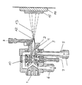
- the plasma torch shown consists of a base body 1, to which an anode 2 and a cathode 3 are attached, electrically insulated from one another. There is an arc zone 4 between the two electrodes, in which the electrical discharge occurs, which is the prerequisite for the formation of a plasma. Because of the high temperature load, the burner is cooled in flow with the aid of a cooling water inlet 5 and a cooling water outlet 6, anode 2 and cathode 3 being reached in equal measure. Argon or an argon-hydrogen mixture is supplied via a separate operating gas connection 7. At the front end of the anode 2 there is a powder feed 8 for entering the matrix material and the materials of the deposits in the plasma flame 12.
- the base body 1 and the cathode 3 are provided with an axial channel 10 through which a carbon-containing gas such as methane or a carbon-containing liquid such as an alcohol is introduced into the reaction zone of the plasma torch.
- a carbon-containing gas such as methane or a carbon-containing liquid such as an alcohol
- This component contains the carbon from which the dispersed diamond hard material is later formed.
- the methane can also be introduced into the plasma via the powder injector tube, ie the powder feed 8 will. All components involved in the coating leave the plasma torch as a spray jet 13 and strike a substrate 14 on which the coating 15 forms.
- the plasma torch together with the substrate 14 can be accommodated in a vacuum chamber, which is not shown in detail. This is continuously kept at a predetermined pressure, for example at a pressure of 50 mbar. Because of the continuously flowing plasma, this vacuum chamber must be kept at this pressure by continuous pumping. However, the introduction of the plasma torch and the substrate 14 into a vacuum chamber is not a requirement, since the coating according to the invention can also be produced under atmospheric pressure or under even higher pressure.
- the operating gas required to operate the plasma torch is argon or another noble gas with a certain proportion of hydrogen.
- the hydrogen has the property of etching away already formed graphite when the layer is formed, so that the presence of hydrogen also contributes to the reduction of the graphite content.
- these phenomena are known in themselves.
- the coating according to the invention is of course also successful if the carbon carrier in the form of a gas or a liquid such as e.g. Alcohol is introduced into the plasma flame 12, for example in or opposite the powder feed 8. It is then ensured in any case that no deposits can form in the Laval nozzle inside the anode 2.
- a gas or a liquid such as e.g. Alcohol
- the substrate is brought into the zone of a high radical concentration to a greater or lesser extent; on the other hand, in the range of low radical concentrations, a carbide former is added to the matrix material, which in addition to the hydrogen for the precipitation of the carbon, which does not condense in the diamond modification, worries.
- a carbide former is added to the matrix material, which in addition to the hydrogen for the precipitation of the carbon, which does not condense in the diamond modification, worries.
- the substrate is arranged in a zone of high radical concentration, the substrate usually has to be cooled, but this is not a serious obstacle. The easiest way to cool the substrate is to spray it under water.
- a grading can of course also be achieved with the method according to the invention, that is to say a change in the ratio between matrix and hard material storage measured over the layer thickness.
- a grading between the matrix and the storage there can of course also be multiple gradings, e.g. a tungsten, tungsten-molybdenum or a vanadium layer is injected, which slowly changes into titanium or tantalum, which in turn form the matrix for the diamond particles.
- a transition to another matrix material can also be formed in addition to the titanium or tantalum, e.g. to a highly active carbide former, in which case the aforementioned layer serves as a barrier layer.
- the invention can be used wherever a matrix can be applied to a substrate with good success, so that adhesion, porosity, cracking and the like are satisfactory.
Landscapes
- Chemical & Material Sciences (AREA)
- Engineering & Computer Science (AREA)
- Plasma & Fusion (AREA)
- Physics & Mathematics (AREA)
- Organic Chemistry (AREA)
- Chemical Kinetics & Catalysis (AREA)
- Materials Engineering (AREA)
- Mechanical Engineering (AREA)
- Metallurgy (AREA)
- General Chemical & Material Sciences (AREA)
- Inorganic Chemistry (AREA)
- Coating By Spraying Or Casting (AREA)
- Chemical Vapour Deposition (AREA)
- Crystals, And After-Treatments Of Crystals (AREA)
- Drying Of Semiconductors (AREA)
- Container, Conveyance, Adherence, Positioning, Of Wafer (AREA)
Abstract
Claims (7)
- Procédé d'application d'un revêtement sur un substrat à l'aide d'un brûleur à plasma, sous la forme d'un procédé de pulvérisation thermique, dans le cas duquel le revêtement est constitué d'une matrice, comme couche d'usage, et d'inclusions pour améliorer les propriétés de la matrice, ou est constitué d'une matrice comme matériau de liaison comportant des particules intégrées à l'intérieur, qui forment la couche d'usage proprement dite, avec les mesures suivantes:- exploitation d'un brûleur à plasma avec arrivée de poudre pour réalisation de la matrice,- amenée, au brûleur à plasma, de gaz ou d'un liquide contenant du carbone et se présentant sous la forme d'un composé destiné à former des particules de diamant, du genre diamant, incluses ou englobées,- ajustement de la distance entre le substrat et la buse du brûleur à plasma, pour déterminer la concentration en radicaux libres de la flamme du plasma au voisinage direct du substrat, une distance faible procurant une concentration élevée et une distance sensiblement de la longueur de la flamme procurant une concentration faible,- l'apport à la poudre de corps carburants, en fonction de la distance ajustée entre le substrat et la buse du brûleur à plasma, une distance faible déterminant un faible apport, et une distance sensiblement de la longueur de la flamme déterminant un apport plus important,- le cas échéant, refroidissement du substrat dans le cas de faibles distances jusqu'à la buse du brûleur à plasma.
- Procédé suivant la revendication 1, dans le cas duquel le gaz ou le liquide contenant du carbone est amené au centre, par un canal situé au centre du brûleur à plasma, ou est y amené radialement.
- Procédé suivant la revendication 1 ou la revendication 2, caractérisé en ce qu'à la poudre, est ajouté un élément dissolvant le carbone, par exemple du cobalt.
- Procédé suivant l'une des revendications 1 à 3, caractérisé en ce que la poudre pour la matrice est une poudre métallique, céramique ou un mélange des deux, c'est-à-dire un cermet.
- Procédé suivant la revendication 1, dans le cas duquel du méthane (CH4) est envoyé comme gaz contenant du carbone.
- Procédé suivant la revendication 1, dans le cas duquel, pour éviter la formation de graphite, de l'hydrogène est ajouté au gaz de fonctionnement du brûleur à plasma.
- Procédé suivant la revendication 1, dans le cas duquel le brûleur à plasma est alimenté en gaz réactifs contenant du silicium, de l'azote et/ou du bore, pour former d'autres inclusions correspondantes.
Applications Claiming Priority (3)
| Application Number | Priority Date | Filing Date | Title |
|---|---|---|---|
| DE4112156 | 1991-04-13 | ||
| DE4112156A DE4112156A1 (de) | 1991-04-13 | 1991-04-13 | Mit hilfe eines plasmabrenners aufgebrachte beschichtung sowie plasmabrenner |
| PCT/EP1992/000816 WO1992018664A1 (fr) | 1991-04-13 | 1992-04-10 | Procede pour appliquer un revetement sur un substrat, revetement et torche a plasma |
Publications (2)
| Publication Number | Publication Date |
|---|---|
| EP0536355A1 EP0536355A1 (fr) | 1993-04-14 |
| EP0536355B1 true EP0536355B1 (fr) | 1996-08-21 |
Family
ID=6429542
Family Applications (1)
| Application Number | Title | Priority Date | Filing Date |
|---|---|---|---|
| EP92908161A Expired - Lifetime EP0536355B1 (fr) | 1991-04-13 | 1992-04-10 | Procede pour appliquer un revetement sur un substrat |
Country Status (5)
| Country | Link |
|---|---|
| EP (1) | EP0536355B1 (fr) |
| JP (1) | JPH05509361A (fr) |
| CA (1) | CA2085246A1 (fr) |
| DE (2) | DE4112156A1 (fr) |
| WO (1) | WO1992018664A1 (fr) |
Families Citing this family (4)
| Publication number | Priority date | Publication date | Assignee | Title |
|---|---|---|---|---|
| DE4109979C2 (de) * | 1990-03-28 | 2000-03-30 | Nisshin Flour Milling Co | Verfahren zur Herstellung beschichteter Teilchen aus anorganischen oder metallischen Materialien |
| DE19958473A1 (de) * | 1999-12-04 | 2001-06-07 | Bosch Gmbh Robert | Verfahren zur Herstellung von Kompositschichten mit einer Plasmastrahlquelle |
| DE19958474A1 (de) * | 1999-12-04 | 2001-06-21 | Bosch Gmbh Robert | Verfahren zur Erzeugung von Funktionsschichten mit einer Plasmastrahlquelle |
| US12385130B2 (en) * | 2017-12-28 | 2025-08-12 | National University Corporation Ehime University | Device for forming diamond film etc. and method therefor |
Citations (2)
| Publication number | Priority date | Publication date | Assignee | Title |
|---|---|---|---|---|
| EP0469204A1 (fr) * | 1990-08-03 | 1992-02-05 | Fujitsu Limited | Méthode pour déposer en phase vapeur un film de diamant |
| EP0481722A1 (fr) * | 1990-10-17 | 1992-04-22 | Fujitsu Limited | Procédé et appareillage pour la production d'un film de revêtement |
-
1991
- 1991-04-13 DE DE4112156A patent/DE4112156A1/de not_active Withdrawn
-
1992
- 1992-04-10 CA CA002085246A patent/CA2085246A1/fr not_active Abandoned
- 1992-04-10 WO PCT/EP1992/000816 patent/WO1992018664A1/fr not_active Ceased
- 1992-04-10 EP EP92908161A patent/EP0536355B1/fr not_active Expired - Lifetime
- 1992-04-10 DE DE59206944T patent/DE59206944D1/de not_active Expired - Fee Related
- 1992-04-10 JP JP4507652A patent/JPH05509361A/ja active Pending
Patent Citations (2)
| Publication number | Priority date | Publication date | Assignee | Title |
|---|---|---|---|---|
| EP0469204A1 (fr) * | 1990-08-03 | 1992-02-05 | Fujitsu Limited | Méthode pour déposer en phase vapeur un film de diamant |
| EP0481722A1 (fr) * | 1990-10-17 | 1992-04-22 | Fujitsu Limited | Procédé et appareillage pour la production d'un film de revêtement |
Non-Patent Citations (1)
| Title |
|---|
| FUJITSU-SCIENTIFIC AND TECHNICAL JOURNAL. Bd. 25, Nr. 1, 1989, KAWASAKI JP, Seiten 44-51 * |
Also Published As
| Publication number | Publication date |
|---|---|
| DE4112156A1 (de) | 1992-10-15 |
| JPH05509361A (ja) | 1993-12-22 |
| WO1992018664A1 (fr) | 1992-10-29 |
| DE59206944D1 (de) | 1996-09-26 |
| EP0536355A1 (fr) | 1993-04-14 |
| CA2085246A1 (fr) | 1992-10-14 |
Similar Documents
| Publication | Publication Date | Title |
|---|---|---|
| EP1242649B1 (fr) | Procede de production de couches composites avec une source de jet de plasma | |
| EP2355126B1 (fr) | Couche dure | |
| DE60130827T2 (de) | Verfahren zur Herstellung von Gegenständen mit gestaffelten Beschichtungen | |
| DE2920198C2 (de) | Pulver zum Auftragen auf ein Metallsubstrat zur Ausbildung eines Überzugs mit hoher Verschleißfestigkeit und Korrosionsbeständigkeit | |
| EP1362931B2 (fr) | Procédé et dispositif pour la fabrication d'un système de couches de DLC | |
| DE69318856T2 (de) | Beschichtete Formkörper | |
| EP0748395B1 (fr) | Procede de fabrication de couches de nitrure de bore cubique | |
| DE2330545A1 (de) | Vorrichtung und verfahren zum ablagern eines karbidfilmes | |
| WO2006099758A2 (fr) | Procede d'utilisation d'une source d'arc pulsee | |
| DE102011051260A1 (de) | Verfahren und Vorrichtung zum Abscheiden von OLEDs | |
| EP0478909A1 (fr) | Procédé et appareillage pour la fabrication d'une couche de diamant | |
| EP1252365A1 (fr) | Procede de production de couches fonctionnelles avec une source de jet de plasma | |
| EP0845053B1 (fr) | Corps composite et son procede de production | |
| DE10256257A1 (de) | Vorrichtung und Verfahren zum Beschichten eines Substrates und Beschichtung auf einem Substrat | |
| EP1479788B1 (fr) | Procédé hybride thermique pour le dépôt d'un revêtment sur un substrat | |
| DE69029729T2 (de) | Verfahren zur Abscheidung aus der Gasphase eines Diamantfilmes | |
| WO1992018664A1 (fr) | Procede pour appliquer un revetement sur un substrat, revetement et torche a plasma | |
| EP0425623A1 (fr) | Procede pour appliquer un materiau ceramique. | |
| DE69922479T2 (de) | Verbesserte Stranggusskikille | |
| DE3014258A1 (de) | Verfahren zum aufbringen von metallischen, metalloidischen oder keramischen schichten mit verbesserten strukturellen eigenschaften durch plasmaspruehen | |
| EP0791226B1 (fr) | Dispositif pour le recouvrement de substrats au moyen d'un materiau en phase vapeur, sous pression reduite ou sous vide | |
| DE102010036332B4 (de) | Verfahren zum Beschichten von Elektroden für die Elektrolyse mittels eines Lichtbogens | |
| DE19538046C2 (de) | Schichtsystem | |
| DE19538045C1 (de) | Vorrichtung zur Beschichtung von Substraten | |
| DE10234856A1 (de) | Einrichtung zum Beschichten durch Magnetron-Sputtern |
Legal Events
| Date | Code | Title | Description |
|---|---|---|---|
| PUAI | Public reference made under article 153(3) epc to a published international application that has entered the european phase |
Free format text: ORIGINAL CODE: 0009012 |
|
| AK | Designated contracting states |
Kind code of ref document: A1 Designated state(s): AT BE CH DE DK ES FR GB GR IT LI LU NL SE |
|
| 17P | Request for examination filed |
Effective date: 19930428 |
|
| 17Q | First examination report despatched |
Effective date: 19941117 |
|
| GRAH | Despatch of communication of intention to grant a patent |
Free format text: ORIGINAL CODE: EPIDOS IGRA |
|
| GRAH | Despatch of communication of intention to grant a patent |
Free format text: ORIGINAL CODE: EPIDOS IGRA |
|
| GRAA | (expected) grant |
Free format text: ORIGINAL CODE: 0009210 |
|
| RBV | Designated contracting states (corrected) |
Designated state(s): DE FR IT LU SE |
|
| AK | Designated contracting states |
Kind code of ref document: B1 Designated state(s): DE FR IT LU SE |
|
| REF | Corresponds to: |
Ref document number: 59206944 Country of ref document: DE Date of ref document: 19960926 |
|
| ET | Fr: translation filed | ||
| ITF | It: translation for a ep patent filed | ||
| PG25 | Lapsed in a contracting state [announced via postgrant information from national office to epo] |
Ref country code: SE Effective date: 19970411 |
|
| PG25 | Lapsed in a contracting state [announced via postgrant information from national office to epo] |
Ref country code: LU Free format text: LAPSE BECAUSE OF NON-PAYMENT OF DUE FEES Effective date: 19970430 |
|
| PLBE | No opposition filed within time limit |
Free format text: ORIGINAL CODE: 0009261 |
|
| 26N | No opposition filed | ||
| PG25 | Lapsed in a contracting state [announced via postgrant information from national office to epo] |
Ref country code: FR Free format text: LAPSE BECAUSE OF NON-PAYMENT OF DUE FEES Effective date: 19971231 |
|
| PG25 | Lapsed in a contracting state [announced via postgrant information from national office to epo] |
Ref country code: DE Free format text: LAPSE BECAUSE OF NON-PAYMENT OF DUE FEES Effective date: 19980101 |
|
| EUG | Se: european patent has lapsed |
Ref document number: 92908161.0 |
|
| REG | Reference to a national code |
Ref country code: FR Ref legal event code: ST |
|
| PG25 | Lapsed in a contracting state [announced via postgrant information from national office to epo] |
Ref country code: IT Free format text: LAPSE BECAUSE OF NON-PAYMENT OF DUE FEES Effective date: 20050410 |