EP0536403A1 - Moteur eolien - Google Patents
Moteur eolien Download PDFInfo
- Publication number
- EP0536403A1 EP0536403A1 EP91914675A EP91914675A EP0536403A1 EP 0536403 A1 EP0536403 A1 EP 0536403A1 EP 91914675 A EP91914675 A EP 91914675A EP 91914675 A EP91914675 A EP 91914675A EP 0536403 A1 EP0536403 A1 EP 0536403A1
- Authority
- EP
- European Patent Office
- Prior art keywords
- wind
- prime mover
- wind power
- receiving members
- rotary shaft
- Prior art date
- Legal status (The legal status is an assumption and is not a legal conclusion. Google has not performed a legal analysis and makes no representation as to the accuracy of the status listed.)
- Granted
Links
Images
Classifications
-
- F—MECHANICAL ENGINEERING; LIGHTING; HEATING; WEAPONS; BLASTING
- F03—MACHINES OR ENGINES FOR LIQUIDS; WIND, SPRING, OR WEIGHT MOTORS; PRODUCING MECHANICAL POWER OR A REACTIVE PROPULSIVE THRUST, NOT OTHERWISE PROVIDED FOR
- F03D—WIND MOTORS
- F03D3/00—Wind motors with rotation axis substantially perpendicular to the air flow entering the rotor
- F03D3/06—Rotors
-
- F—MECHANICAL ENGINEERING; LIGHTING; HEATING; WEAPONS; BLASTING
- F03—MACHINES OR ENGINES FOR LIQUIDS; WIND, SPRING, OR WEIGHT MOTORS; PRODUCING MECHANICAL POWER OR A REACTIVE PROPULSIVE THRUST, NOT OTHERWISE PROVIDED FOR
- F03D—WIND MOTORS
- F03D3/00—Wind motors with rotation axis substantially perpendicular to the air flow entering the rotor
- F03D3/005—Wind motors with rotation axis substantially perpendicular to the air flow entering the rotor the axis being vertical
-
- F—MECHANICAL ENGINEERING; LIGHTING; HEATING; WEAPONS; BLASTING
- F05—INDEXING SCHEMES RELATING TO ENGINES OR PUMPS IN VARIOUS SUBCLASSES OF CLASSES F01-F04
- F05B—INDEXING SCHEME RELATING TO WIND, SPRING, WEIGHT, INERTIA OR LIKE MOTORS, TO MACHINES OR ENGINES FOR LIQUIDS COVERED BY SUBCLASSES F03B, F03D AND F03G
- F05B2240/00—Components
- F05B2240/20—Rotors
- F05B2240/21—Rotors for wind turbines
- F05B2240/211—Rotors for wind turbines with vertical axis
- F05B2240/216—Rotors for wind turbines with vertical axis of the anemometer type
-
- F—MECHANICAL ENGINEERING; LIGHTING; HEATING; WEAPONS; BLASTING
- F05—INDEXING SCHEMES RELATING TO ENGINES OR PUMPS IN VARIOUS SUBCLASSES OF CLASSES F01-F04
- F05B—INDEXING SCHEME RELATING TO WIND, SPRING, WEIGHT, INERTIA OR LIKE MOTORS, TO MACHINES OR ENGINES FOR LIQUIDS COVERED BY SUBCLASSES F03B, F03D AND F03G
- F05B2260/00—Function
- F05B2260/40—Transmission of power
- F05B2260/403—Transmission of power through the shape of the drive components
- F05B2260/4031—Transmission of power through the shape of the drive components as in toothed gearing
-
- Y—GENERAL TAGGING OF NEW TECHNOLOGICAL DEVELOPMENTS; GENERAL TAGGING OF CROSS-SECTIONAL TECHNOLOGIES SPANNING OVER SEVERAL SECTIONS OF THE IPC; TECHNICAL SUBJECTS COVERED BY FORMER USPC CROSS-REFERENCE ART COLLECTIONS [XRACs] AND DIGESTS
- Y02—TECHNOLOGIES OR APPLICATIONS FOR MITIGATION OR ADAPTATION AGAINST CLIMATE CHANGE
- Y02E—REDUCTION OF GREENHOUSE GAS [GHG] EMISSIONS, RELATED TO ENERGY GENERATION, TRANSMISSION OR DISTRIBUTION
- Y02E10/00—Energy generation through renewable energy sources
- Y02E10/70—Wind energy
- Y02E10/74—Wind turbines with rotation axis perpendicular to the wind direction
-
- Y—GENERAL TAGGING OF NEW TECHNOLOGICAL DEVELOPMENTS; GENERAL TAGGING OF CROSS-SECTIONAL TECHNOLOGIES SPANNING OVER SEVERAL SECTIONS OF THE IPC; TECHNICAL SUBJECTS COVERED BY FORMER USPC CROSS-REFERENCE ART COLLECTIONS [XRACs] AND DIGESTS
- Y02—TECHNOLOGIES OR APPLICATIONS FOR MITIGATION OR ADAPTATION AGAINST CLIMATE CHANGE
- Y02P—CLIMATE CHANGE MITIGATION TECHNOLOGIES IN THE PRODUCTION OR PROCESSING OF GOODS
- Y02P70/00—Climate change mitigation technologies in the production process for final industrial or consumer products
- Y02P70/50—Manufacturing or production processes characterised by the final manufactured product
Definitions
- the present invention relates to a wind power prime mover which is suitable for a power generating equipment by wind power.
- the present invention has been executed and improved in consideration to the above mentioned prior aspects of the electricity generation by wind power, therefore the invention aims to provide a wind power prime mover which is hardly affected by an instantaneous variation of wind velocity, of which costs of manufacturing, transport, assembly and maintenance are comparatively reasonable, and which is suitable for the electricity power generating equipment being hardly restricted to the location of installation.
- the present invention aims to execute the above-mentioned objects by constructing a wind power prime mover in which a windmill assembly comprising semicylindrical wind receiving members vertically erected on a plurality of equally spaced points on the circumference centering on a vertical rotary shaft in such manner that semicylindrical open parts of said wind receiving members are directed to the same circumferential directions with respect to individual tangents to said circumference and of knock-down-assembly construction with the major parts thereof joined to or disjoined from each other, and each of the top and bottom of said vertical rotary shaft are supported.
- this wind power prime mover can be designed to have comparatively lower height, as its plural semicylindrical wind receiving members are being horizontally rotated centering on a vertical rotary shaft, and also this prime mover is hardly affected by an instantaneous variation of wind velocity due to the flywheel effect being a fairly big rotary inertia moment, and furthermore, as the said prime mover is constructed with the major parts thereof joined to each other, the selection of its location is found easily and freely, and the costs of manufacturing, delivery, assembling and construction of the said prime mover are reasonable, and the said prime mover can be installed, for example, on the roof of the building, and its maintenance is easily executed because its height from the ground or from the floor is low.
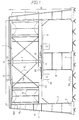
- FIG. 1 shows an outline side view of an embodiment of power generator utilizing a wind power prime mover of the present invention
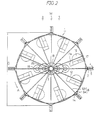
- FIG. 2 is a top view of FIG. 1.
- FIG. 1 an outline side view of an embodiment of power generator in relation to the present invention, shows that a wind power prime mover (hereinafter referred to as Windmill) 1 is installed on the ground level (GL) or on the floor level (FL), in which Windmill 1 is constructed with rotating horizontally around a vertical rotary shaft 3 inside eight supports 2, opposite diameter of which are disposed under regular octagonally.
- Windmill wind power prime mover
- each support 2 is provided with reinforcing support 4, and these supports 2 and 4 are fixed and installed upon each basic concrete 5 on the ground level GL or floor level FL, in which an upper frame 6 is composed of each frame member 6a mutually connecting between the adjacent supports and also between the diametrically opposed supports at the top of each support.
- a central support frame 8 having adequate height is formed upon the basic concrete 7 on the ground level GL of the center of the octagon being formed to each support 1, then, a lower frame 9 is constructed with each frame member similar to the aforementioned upper frame 6, including its top members.
- a Windmill 1 has each upper/lower rotating members 12/13 extending radially from each vertically rotating shaft with equally spaced eight angles in which the top parts of each member 12/13 are jointly reinforced by circular members 14 , and each set of upper/lower rotating members 12/13 corresponding to the upper and lower sides applied and reinforced in hardness by a reinforcing members 15 as diagonal members independently disposed in X shape.
- semicylindrical wind receiving members 16 having semicircular cross section are mounted firmly and vertically in such manner that their semicylindrical open parts are directed to the same circumferential directions with respect to individual tangents to said circumferenece, and a regulating plate 17 having a shape of vertical flat board is mounted firmly at the both of two vertical extreme parts and center of said semicylindrical open parts, and also a regulating plate 17a broader than said regulating plate 17 is mounted firmly at a little to center of said inside vertical extreme parts. Also, each of an upper and a lower extreme parts of each wind receiving members 16 are formed in slope by each semicircular plate 16a. A horizontal regulating plate having a plurality of radius direction may be disposed on said vertical regulating plates 17 and 17a.
- said major composing parts of Windmill are of assembly construction manufactured by mainly angle steel and steel plate thereof joined to each other with bolts, and therefore, its dismantling, transport, assembly, maintenance and so forth are designed to be of easy care.
- Windmill 1 Based upon the said construction, in FIG. 2, if this Windmill 1 receives wind from the direction of the arrow, Windmill is under a high motive pressure within the semicylindrical inside of each wind receiving members 16 in the left side of the drawing, meanwhile, in the right side of the drawing, the resistance to wind power is smaller because of smooth circumference of semicyrindrical parts. Windmill 1 generates rotary power rotating to the direction A of arrow by rotating power generated from the difference between the resistance values of wind power of said both left and right sides. And also this Windmill has fairly big rotary inertia moment from its structure, then it can be expected to provide a big flywheel effect, thereby it is hardly affected by an instantenous variation of wind velocity after it starts the rotation.
- a big toothed wheel 19 is firmly mounted on the lower part of rotary shaft 3 concentrically, and a small toothed wheel (pinion) 20, which is in gear with a big toothed wheel 19 respectively and is for the multiplying purpose, is also firmly mounted on a separate shaft respectively at the opposed diametrical location.
- Another big toothed wheel is mounted at the lower part of each pinion 20 which is constructed for multiplying each power generator by the rotary power of each second pinion shaft being mounted upon said each separate shaft.
- a braking system may be equipped to support compulsorily each circular material 14 as the parts braked at the upper and lower parts of Windmill, which is utilized to stop Windmill when maintenance and inspection are required.
- wind power prime mover of the present invention is constructed in the assembly comprising a plurality of semicylindrical wind receiving members horizontally rotating around vertically erected rotary shaft equally spaced and disposed on the circumference of Windmill, therefore this prime mover is expected to have comparatively grealer flywheel effect, has also not so tall, and is constructed with the major parts thereof joined to each other, the selection of its location is comparatively found easily and freely, and it is very advantageous for manufacturing, transferring, assembling and maintenance.
Landscapes
- Engineering & Computer Science (AREA)
- Life Sciences & Earth Sciences (AREA)
- Sustainable Development (AREA)
- Sustainable Energy (AREA)
- Chemical & Material Sciences (AREA)
- Combustion & Propulsion (AREA)
- Mechanical Engineering (AREA)
- General Engineering & Computer Science (AREA)
- Wind Motors (AREA)
Abstract
Applications Claiming Priority (3)
| Application Number | Priority Date | Filing Date | Title |
|---|---|---|---|
| JP55215/91 | 1991-03-20 | ||
| JP3055215A JPH04292579A (ja) | 1991-03-20 | 1991-03-20 | 風力原動機 |
| PCT/JP1991/001116 WO1992016745A1 (fr) | 1991-03-20 | 1991-08-22 | Moteur eolien |
Publications (3)
| Publication Number | Publication Date |
|---|---|
| EP0536403A1 true EP0536403A1 (fr) | 1993-04-14 |
| EP0536403A4 EP0536403A4 (en) | 1993-08-04 |
| EP0536403B1 EP0536403B1 (fr) | 1997-03-12 |
Family
ID=12992401
Family Applications (1)
| Application Number | Title | Priority Date | Filing Date |
|---|---|---|---|
| EP91914675A Expired - Lifetime EP0536403B1 (fr) | 1991-03-20 | 1991-08-22 | Moteur eolien |
Country Status (4)
| Country | Link |
|---|---|
| EP (1) | EP0536403B1 (fr) |
| JP (1) | JPH04292579A (fr) |
| AU (1) | AU8393491A (fr) |
| WO (1) | WO1992016745A1 (fr) |
Cited By (3)
| Publication number | Priority date | Publication date | Assignee | Title |
|---|---|---|---|---|
| WO2002014688A1 (fr) * | 2000-08-17 | 2002-02-21 | Hongsun Hua | Eolienne a ossature combinee |
| RU2256093C2 (ru) * | 2000-12-29 | 2005-07-10 | Житников Эдуард Дмитриевич | Устройство ветропривода карусельного типа |
| WO2013032415A1 (fr) * | 2011-08-26 | 2013-03-07 | Syrota Anatolii Vasyliovych | Tour éolienne |
Families Citing this family (4)
| Publication number | Priority date | Publication date | Assignee | Title |
|---|---|---|---|---|
| WO1998020256A1 (fr) * | 1996-11-05 | 1998-05-14 | Kosuke Ota | Eolienne produisant de l'energie |
| US6749393B2 (en) * | 2001-08-13 | 2004-06-15 | Yevgeniya Sosonkina | Wind power plant |
| CN102213180B (zh) * | 2010-04-04 | 2013-07-10 | 李锋 | 一种立轴风力发电机组的风机 |
| RU2508470C2 (ru) * | 2011-08-26 | 2014-02-27 | Владимир Анатольевич Сирота | Сироты башня ветроэнергетическая |
Family Cites Families (6)
| Publication number | Priority date | Publication date | Assignee | Title |
|---|---|---|---|---|
| US4037989A (en) * | 1975-05-12 | 1977-07-26 | Huther Jerome W | Vertical axis wind turbine rotor |
| JPS5381003A (en) * | 1976-12-27 | 1978-07-18 | Nippon Telegr & Teleph Corp <Ntt> | In-band signal system |
| JPS5573561U (fr) * | 1978-11-17 | 1980-05-21 | ||
| JPS58167778U (ja) * | 1982-05-07 | 1983-11-09 | 今永 博彬 | 翼状板による回転装置 |
| JPS61237885A (ja) * | 1985-04-11 | 1986-10-23 | Tadashi Sakaguchi | 風車 |
| DE3638620A1 (de) * | 1986-11-12 | 1988-05-26 | Adrian Van Hees | Windturbine mit senkrechter mittelachse mit lamellenbestueckten windfangmantel mit gedeckten ruecklauf der turbine |
-
1991
- 1991-03-20 JP JP3055215A patent/JPH04292579A/ja active Pending
- 1991-08-22 EP EP91914675A patent/EP0536403B1/fr not_active Expired - Lifetime
- 1991-08-22 AU AU83934/91A patent/AU8393491A/en not_active Abandoned
- 1991-08-22 WO PCT/JP1991/001116 patent/WO1992016745A1/fr not_active Ceased
Cited By (5)
| Publication number | Priority date | Publication date | Assignee | Title |
|---|---|---|---|---|
| WO2002014688A1 (fr) * | 2000-08-17 | 2002-02-21 | Hongsun Hua | Eolienne a ossature combinee |
| AU2000266814B2 (en) * | 2000-08-17 | 2004-02-05 | Hongsun Hua | Windmill |
| EP1310671A4 (fr) * | 2000-08-17 | 2005-06-01 | Hongsun Hua | Eolienne a ossature combinee |
| RU2256093C2 (ru) * | 2000-12-29 | 2005-07-10 | Житников Эдуард Дмитриевич | Устройство ветропривода карусельного типа |
| WO2013032415A1 (fr) * | 2011-08-26 | 2013-03-07 | Syrota Anatolii Vasyliovych | Tour éolienne |
Also Published As
| Publication number | Publication date |
|---|---|
| WO1992016745A1 (fr) | 1992-10-01 |
| AU8393491A (en) | 1992-10-21 |
| EP0536403A4 (en) | 1993-08-04 |
| EP0536403B1 (fr) | 1997-03-12 |
| JPH04292579A (ja) | 1992-10-16 |
Similar Documents
| Publication | Publication Date | Title |
|---|---|---|
| US7948111B2 (en) | Vertical axis wind system | |
| AU694862B2 (en) | Vertical axis wind turbine | |
| JP2015072004A (ja) | 増大した発電効率を有する可変ブレード型潮力及び風力発電機 | |
| WO2009106922A1 (fr) | Éolienne sans arbre, de type cage, présentant un axe vertical | |
| EP4155531A1 (fr) | Éolienne | |
| EP0536403B1 (fr) | Moteur eolien | |
| JP2001050149A (ja) | 風力発電装置 | |
| JP2023037601A (ja) | 現場用の杭頂部動的水平載荷をシミュレートする装置及び方法 | |
| EP2317128A1 (fr) | Éolienne à axe vertical | |
| US6072244A (en) | Wind power prime mover | |
| US20150152840A1 (en) | Dual-Turbine Wind Power Station Placed on a Vertical Axis | |
| CN112065655B (zh) | 叶片调节方法及模块、以及风轮和垂直轴风力发电机 | |
| JP2023095968A (ja) | 風力発電所 | |
| KR102001376B1 (ko) | 타워형 풍력발전기 | |
| RU2115825C1 (ru) | Ветряная электростанция парусная-3 (вэпг-3) | |
| GB2129060A (en) | Vertical axis windmills | |
| EP0533934B1 (fr) | Installation exploitant la force hydraulique | |
| CN100392239C (zh) | 一种垂直轴大功率风力发电机 | |
| JPH08240U (ja) | 風力原動機 | |
| CN221799990U (zh) | 一种多电机并列运行的发电装置 | |
| CN113738585A (zh) | 双机头风电机组及其运行方法 | |
| RU2786849C1 (ru) | Двухосный лопастной вертикальный ветрогенератор | |
| CN221462455U (zh) | 一种垂直轴风力发电机叶轮结构 | |
| KR200359792Y1 (ko) | 브라켓식 높낮이조절장치를 갖는 수평수차 | |
| ES2402455B1 (es) | Sistema amplificador de potencia mediante el aprovechamiento de la fuerza centrífuga y de la gravedad. |
Legal Events
| Date | Code | Title | Description |
|---|---|---|---|
| PUAI | Public reference made under article 153(3) epc to a published international application that has entered the european phase |
Free format text: ORIGINAL CODE: 0009012 |
|
| 17P | Request for examination filed |
Effective date: 19921217 |
|
| AK | Designated contracting states |
Kind code of ref document: A1 Designated state(s): FR IT |
|
| A4 | Supplementary search report drawn up and despatched |
Effective date: 19930615 |
|
| AK | Designated contracting states |
Kind code of ref document: A4 Designated state(s): FR IT |
|
| 17Q | First examination report despatched |
Effective date: 19940525 |
|
| GRAG | Despatch of communication of intention to grant |
Free format text: ORIGINAL CODE: EPIDOS AGRA |
|
| GRAH | Despatch of communication of intention to grant a patent |
Free format text: ORIGINAL CODE: EPIDOS IGRA |
|
| GRAH | Despatch of communication of intention to grant a patent |
Free format text: ORIGINAL CODE: EPIDOS IGRA |
|
| GRAA | (expected) grant |
Free format text: ORIGINAL CODE: 0009210 |
|
| AK | Designated contracting states |
Kind code of ref document: B1 Designated state(s): FR IT |
|
| ITF | It: translation for a ep patent filed | ||
| ET | Fr: translation filed | ||
| PGFP | Annual fee paid to national office [announced via postgrant information from national office to epo] |
Ref country code: FR Payment date: 19970721 Year of fee payment: 7 |
|
| PLBE | No opposition filed within time limit |
Free format text: ORIGINAL CODE: 0009261 |
|
| STAA | Information on the status of an ep patent application or granted ep patent |
Free format text: STATUS: NO OPPOSITION FILED WITHIN TIME LIMIT |
|
| 26N | No opposition filed | ||
| PG25 | Lapsed in a contracting state [announced via postgrant information from national office to epo] |
Ref country code: FR Free format text: LAPSE BECAUSE OF NON-PAYMENT OF DUE FEES Effective date: 19990430 |
|
| REG | Reference to a national code |
Ref country code: FR Ref legal event code: ST |
|
| PG25 | Lapsed in a contracting state [announced via postgrant information from national office to epo] |
Ref country code: IT Free format text: LAPSE BECAUSE OF NON-PAYMENT OF DUE FEES Effective date: 20050822 |