EP0536473A1 - Sous-tête militaire pour emploi à vol rasant - Google Patents
Sous-tête militaire pour emploi à vol rasant Download PDFInfo
- Publication number
- EP0536473A1 EP0536473A1 EP92109035A EP92109035A EP0536473A1 EP 0536473 A1 EP0536473 A1 EP 0536473A1 EP 92109035 A EP92109035 A EP 92109035A EP 92109035 A EP92109035 A EP 92109035A EP 0536473 A1 EP0536473 A1 EP 0536473A1
- Authority
- EP
- European Patent Office
- Prior art keywords
- submunition
- target
- sensor
- carrier
- flight
- Prior art date
- Legal status (The legal status is an assumption and is not a legal conclusion. Google has not performed a legal analysis and makes no representation as to the accuracy of the status listed.)
- Withdrawn
Links
- 238000005259 measurement Methods 0.000 claims description 5
- 230000000737 periodic effect Effects 0.000 claims 1
- 239000002360 explosive Substances 0.000 abstract 1
- 238000001514 detection method Methods 0.000 description 8
- 230000010355 oscillation Effects 0.000 description 4
- 230000008685 targeting Effects 0.000 description 4
- 238000013461 design Methods 0.000 description 3
- 230000000694 effects Effects 0.000 description 3
- 238000012545 processing Methods 0.000 description 2
- 238000005096 rolling process Methods 0.000 description 2
- 230000035945 sensitivity Effects 0.000 description 2
- 239000000969 carrier Substances 0.000 description 1
- 230000006378 damage Effects 0.000 description 1
- 230000001419 dependent effect Effects 0.000 description 1
- 230000007613 environmental effect Effects 0.000 description 1
- 238000011156 evaluation Methods 0.000 description 1
- 230000002349 favourable effect Effects 0.000 description 1
- 238000000034 method Methods 0.000 description 1
- 230000003534 oscillatory effect Effects 0.000 description 1
- 230000006641 stabilisation Effects 0.000 description 1
- 238000011105 stabilization Methods 0.000 description 1
- 230000001960 triggered effect Effects 0.000 description 1
Images


Classifications
-
- F—MECHANICAL ENGINEERING; LIGHTING; HEATING; WEAPONS; BLASTING
- F42—AMMUNITION; BLASTING
- F42C—AMMUNITION FUZES; ARMING OR SAFETY MEANS THEREFOR
- F42C11/00—Electric fuzes
- F42C11/001—Electric circuits for fuzes characterised by the ammunition class or type
- F42C11/002—Smart ammunition fuzes, i.e. having an integrated scanning, guiding and firing system
-
- F—MECHANICAL ENGINEERING; LIGHTING; HEATING; WEAPONS; BLASTING
- F41—WEAPONS
- F41G—WEAPON SIGHTS; AIMING
- F41G3/00—Aiming or laying means
- F41G3/22—Aiming or laying means for vehicle-borne armament, e.g. on aircraft
-
- F—MECHANICAL ENGINEERING; LIGHTING; HEATING; WEAPONS; BLASTING
- F42—AMMUNITION; BLASTING
- F42B—EXPLOSIVE CHARGES, e.g. FOR BLASTING, FIREWORKS, AMMUNITION
- F42B12/00—Projectiles, missiles or mines characterised by the warhead, the intended effect, or the material
- F42B12/02—Projectiles, missiles or mines characterised by the warhead, the intended effect, or the material characterised by the warhead or the intended effect
- F42B12/04—Projectiles, missiles or mines characterised by the warhead, the intended effect, or the material characterised by the warhead or the intended effect of armour-piercing type
- F42B12/10—Projectiles, missiles or mines characterised by the warhead, the intended effect, or the material characterised by the warhead or the intended effect of armour-piercing type with shaped or hollow charge
Definitions
- the present invention relates to a submunition, in particular for low-altitude use, which can be transported to a target area and ejected there by means of a carrier.
- the submunition travels a predetermined distance at a constant, low altitude with a controlled rolling movement, which runs at an angle to the carrier's flight axis, the submunition having a target sensor and an active charge.
- a submunition equipped with a search detonator scans the ground in a decelerating spiral strip in the braked steep descent according to target criteria.
- search fuse submunition either a projectile-forming charge is fired in a targeted manner (search fuse submunition) or the submunition itself is directed to the target.
- the submunition has to be brought to a high starting altitude, which means with air-to-surface weapons either an emission at this height and thus a great danger to the carrier, or a high effort for the ascent of the submunition plus a corresponding distribution of width in the event of a low-altitude launch .
- the submunition is designed as a guided missile with a forward-looking seeker.
- the submunition directs itself automatically to the target after target acquisition, but such a guided missile design is very complex and therefore very expensive.
- both possible solutions require larger target acquisition distances and thus a high sensitivity to influences other than those of the targets to be combated, whereby these targets still have the option of countermeasures; the risk of multiple targets cannot be ruled out.
- a submunition body which can be fired by means of an artillery projectile and can be ejected from it over a target area by executing a rotary movement; the submunition is equipped with a target detection sensor and a combat charge in a hollow cylinder.
- the structurally complex, space-consuming and function-critical measure for the destruction of the kinetic energy after the ejection and for the parachute-braked descent into the target area can be dispensed with by the gyroscopic movement of a dimensioned as a thick disc, ie flat cylinder, body ejected from the carrier floor with self-rotation is used for scanning the target area by means of a target detection sensor spot.
- Such an arrangement is unsuitable for deployment at high airspeeds, since a sufficiently stable position of the body can only be expected at very high internal speeds, but this is not yet technologically controllable for scanning and target accuracy.
- the other is detectable target area, ie the area covered by the spiral movement during low-flying is very limited, especially since only a very short free-flight distance can be used due to the inevitable wobble movement.
- the object of the present invention is to provide a submunition for combating hard, mobile group targets, which can be launched at low altitude, has a high effect against modern main battle tanks, ensures autonomous target recognition with a large search area and offers a low risk of multiple target combat with moderate effort .
- the submunition is provided with an altimeter and with a circuit that evaluates the altitude measurement results and with at least one rudder that can be controlled from this circuit and that is used for altitude and roll control.
- the submunition is ejected from a carrier during flight and controls - guided by the altimeter - a trajectory at low altitude parallel to the contour of the terrain.
- the submunition does not require a drive due to its large kinetic energy, but can be equipped with a drive.
- the submunition In this free flight at a constant low altitude above ground, the submunition continuously searches for targets in a strip below with the help of its target-detecting sensor. When the target is detected, it directs an effective charge onto the target and triggers it.
- the altimeter is advantageously a laser rangefinder, which can also serve as a target contour sensing sensor. Additional sensors can be used as a support or alternatively for target acquisition.
- the submunition is equipped with a laser range finder for height and target measurement, and also with a magnetic field sensor as the second target sensor, which are connected to a circuit which triggers the ignition of the active charge.
- the laser sensor and active charge are rigidly installed axially parallel to the direction of flight.
- the submunition continuously performs an oscillating rolling movement for scanning the search strip and for height measurement.
- the target-detecting sensor and the active charge have a certain broad effect, which is coordinated with one another. Both are again rigidly installed axially parallel to the direction of flight. The submunition flies here without any aim-related roll movements.
- the submunition according to the invention which is particularly suitable for use in fast low-altitude flight, offers a favorable compromise between the cost of the weapon and the required transportation. Due to the small target distance (a range of 20 to 50 m), the requirements for sensors, signal processing and tolerances can be kept low. The small target distance also leads to good target acquisition opportunities, since only small target concealments due to environmental influences are to be expected and there is little sensitivity to weather and countermeasures.
- the submunition according to the invention covers a relatively large area strip of a few thousand m2.
- the overlap of the search strips of several submunitions can be minimized. This means that a high degree of efficiency can be achieved in relation to the weight of the weapon and the entire target area, i.e. a high probability for the detection of all individual parts and a low probability for double combat of the mobile targets.
- the submunition according to the invention can also be used to combat other groups of mobile targets or also the position according to only roughly known vehicles, such as Rocket positions, helicopter bases, motorized rifle companies, artillery positions, control stations, etc.
- the trajectory can be curved horizontally either by structural design or selectable by appropriate roll control.
- the arrow running to the right denotes a submunition carrier track, which therefore takes the carrier that ejects one or more submunitions.
- a submunition After the release of a submunition, it goes into gliding flight and controls the predetermined height above ground, which e.g. With its height-maintaining device, it is 20 m and holds it until the minimum flight speed is undershot.
- the flight course over the ground is not guided and runs essentially in a straight line at an angle to the carrier web, which depends on the ejection conditions (FIG. 1c).
- the submunition controls its rollage so that its targeting sensor looks at the ground.
- the target detection device is pivoted continuously, essentially perpendicular to the flight axis, and thus searches for targets in a strip below the submunition (FIG. 1b).
- the target detection device has a wide detection window.
- the active charge is triggered, which is aligned with the target parallel to the axis of the target acquisition device.
- the carrier can contain a large number of submunitions, which are ejected in a defined sequence, possibly also adapted to the target geometry, in such a way that the search strips of the individual submunitions lie next to one another. As is indicated in FIG. 1c, the entire target area is thus searched for targets x.
- a narrow, undetected alley remains below the carrier path, which is dependent on the ejection height and which is due to the fact that the submunitions are only activated for a certain time after ejection from the carrier in such a way that they target the region below them can scan for targets.
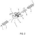
- Fig. 2 shows the schematic structure of a submunition according to the invention, with 1 denoting the main axis in the direction of flight, with 2 meandering arrows which are intended to indicate an oscillation around the main axis 1, with 3 an active charge, e.g. a projectile-forming hollow charge with a suitable securing device, with 4 the axis of the shaped charge, with 5 a height and target sensor, with 6 a second target sensor, with 7 a pair of adjustable rudders serving for height and roll control, with 8 a rigid tail unit for aerodynamic stabilization and with 9 a power supply and a signal processing circuit both for the target sensor system and for the roll and height control.
- active charge e.g. a projectile-forming hollow charge with a suitable securing device
- 4 the axis of the shaped charge
- 5 a height and target sensor
- 6 a second target sensor
- 7 a pair of adjustable rudders serving for height and roll control
- 8 a rigid tail unit for aero
- a laser rangefinder is particularly suitable as an altimeter, which can be used not only for height information, but also for target acquisition by measuring the characteristic target contours.
- a second target sensor for example a magnetic sensor, is provided, which supplies a second target determination criterion.
- the laser sensor is arranged such that its sensor direction essentially runs perpendicular to the main axis 1 of the submunition.
- the adjustable aerodynamic surfaces, ie the wings or rudders 7, serve to maintain a substantially constant distance above the ground and to hold the target-measuring laser sensor with the direction of detection to the ground.
- the submunition is e.g. high transverse speed ejected from a carrier in fast low-altitude flight at a speed of e.g. 0.8 Ma and at a height of 40 m. It unfolds into a free-flight configuration, stabilizes its main axis in the direction of flight and, with the help of its rudders 7, sets in rapid oscillatory movements.
- the laser range finder 6 determines - starting with its max. Detection range - the shortest echo range with each vibration of the submunition. This is interpreted as a height above ground and vertical, the control element for the rudder 7 being actuated depending on the distance in such a way that the predetermined target height of, for example, 20 m is controlled. At this height, the submunition glides over the ground (Fig. 1a). Furthermore, the rudders are deflected by superimposing a roll command for oscillation and height control so that the vertical corresponds to the center of the oscillation oscillation.
- the second target sensor for example a magnetic sensor, searches for target criteria. If this sensor responds in the presence of battle tanks, the signal from the altimeter, ie the laser rangefinder, is evaluated for changes in height profile, for example, which are characteristic of large vehicles. Such a jump in height with a simultaneous positive target message from the second sensor is interpreted as the target and the projectile-forming charge is ignited. As a result of their position parallel to the axis of the laser, the active charge is shot in a direction in which, according to the contour evaluation, the target lies.
- the signal from the altimeter ie the laser rangefinder
- 3a to d show sections through the submunition in planes perpendicular to the trajectory.
- 3a shows the shortest distance, which is interpreted as height above ground and vertical.
- Fig. 3c shows that a target has been detected and
- Fig. 3d shows schematically the fight against this target.
- 4a to d show these phases of targeting in plan view.
- the ignition timing can be chosen such that the maximum effect is achieved, e.g. an angle of impact that is as steep as possible or the control of horizontal high areas, e.g. the surfaces of the main battle tanks.
- the control circuit 9 can work with a time offset compared to the passage of the minimum distance, so that, depending on the setting, trajectories curved to the right or left can be generated over the ground. This means e.g. Course variations of submunitions emitted at the same time or in the same direction are possible, i.e. less double coverage of a strip of land or also reduction or closure of uncovered strips, i.e. the alleys below the beam (Fig. 1c).
- the setting of the courses followed by the submunitions can be determined by the carrier.
- optimal surface coverage can be achieved in spite of structurally identical submunition, and the detected surface can also be adapted to the relative position of the carrier-target and the target geometry.
- the submunition according to the invention enables a high combat probability even against widely spread main battle tanks from deep flight, with effective use of the weapon weight and moderate costs.
Landscapes
- Engineering & Computer Science (AREA)
- General Engineering & Computer Science (AREA)
- Aviation & Aerospace Engineering (AREA)
- Chemical & Material Sciences (AREA)
- Combustion & Propulsion (AREA)
- Aiming, Guidance, Guns With A Light Source, Armor, Camouflage, And Targets (AREA)
- Control Of Position, Course, Altitude, Or Attitude Of Moving Bodies (AREA)
Applications Claiming Priority (2)
| Application Number | Priority Date | Filing Date | Title |
|---|---|---|---|
| DE4133405A DE4133405C2 (de) | 1991-10-09 | 1991-10-09 | Submunition für Tiefflugeinsatz |
| DE4133405 | 1991-10-09 |
Publications (1)
| Publication Number | Publication Date |
|---|---|
| EP0536473A1 true EP0536473A1 (fr) | 1993-04-14 |
Family
ID=6442322
Family Applications (1)
| Application Number | Title | Priority Date | Filing Date |
|---|---|---|---|
| EP92109035A Withdrawn EP0536473A1 (fr) | 1991-10-09 | 1992-05-29 | Sous-tête militaire pour emploi à vol rasant |
Country Status (3)
| Country | Link |
|---|---|
| US (1) | US5301614A (fr) |
| EP (1) | EP0536473A1 (fr) |
| DE (1) | DE4133405C2 (fr) |
Cited By (2)
| Publication number | Priority date | Publication date | Assignee | Title |
|---|---|---|---|---|
| FR2721997A1 (fr) * | 1994-07-01 | 1996-01-05 | Thomson Csf | Systeme individuel de grenade intelligente et son moyen de lancement |
| RU2274823C1 (ru) * | 2004-09-13 | 2006-04-20 | Научно-исследовательский институт специального машиностроения Московского государственного технического университета им. Н.Э. Баумана | Танковый противовертолетный снаряд |
Families Citing this family (4)
| Publication number | Priority date | Publication date | Assignee | Title |
|---|---|---|---|---|
| SE505189C2 (sv) * | 1994-11-16 | 1997-07-14 | Bofors Ab | Sätt och anordning för att med från en bärfarkost frigjorda stridsdelar bekämpa längs bärfarkostens färdväg identifierade mål |
| DE29703458U1 (de) * | 1997-02-27 | 1997-04-30 | Schmitz, Oliver, 60325 Frankfurt | Lasche für Druckerzeugnisse |
| AUPQ524000A0 (en) * | 2000-01-24 | 2000-06-15 | Metal Storm Limited | Anti-missile missiles |
| AU2002950846A0 (en) * | 2002-08-16 | 2002-09-12 | Metal Storm Limited | Interception missile and method of interception |
Citations (5)
| Publication number | Priority date | Publication date | Assignee | Title |
|---|---|---|---|---|
| EP0071757A2 (fr) * | 1981-08-05 | 1983-02-16 | Rheinmetall GmbH | Dispositif de contrôle de la position d'un missile |
| DE3323685A1 (de) * | 1983-07-01 | 1985-01-10 | Dornier Gmbh, 7990 Friedrichshafen | Einrichtung zur bekaempfung von bodenzielen aus der luft |
| DE3345601C2 (de) * | 1983-12-16 | 1986-01-09 | Diehl GmbH & Co, 8500 Nürnberg | Submunitionskörper |
| DE3421140A1 (de) * | 1984-06-07 | 1986-01-30 | Messerschmitt-Bölkow-Blohm GmbH, 8012 Ottobrunn | Verfahren zur ortung und zielsuche von mit motorkraft angetriebenen zielen und munitionskoerper zur durchfuehrung des verfahrens |
| DE3843006A1 (de) * | 1988-12-21 | 1990-06-28 | Messerschmitt Boelkow Blohm | Vorrichtung fuer das auffinden und die identifizierung von einzelzielen |
Family Cites Families (7)
| Publication number | Priority date | Publication date | Assignee | Title |
|---|---|---|---|---|
| US3964694A (en) * | 1967-02-14 | 1976-06-22 | The United States Of America As Represented By The Secretary Of The Army | Aerial acoustic target seeker |
| US4522356A (en) * | 1973-11-12 | 1985-06-11 | General Dynamics, Pomona Division | Multiple target seeking clustered munition and system |
| DE2538665A1 (de) * | 1975-08-30 | 1977-03-10 | Messerschmitt Boelkow Blohm | Verfahren und einrichtung zum streuwurf von bomben |
| FR2406800A1 (fr) * | 1977-10-18 | 1979-05-18 | Aerospatiale | Missile d'attaque en survol |
| US4172407A (en) * | 1978-08-25 | 1979-10-30 | General Dynamics Corporation | Submunition dispenser system |
| US4417520A (en) * | 1980-04-14 | 1983-11-29 | General Dynamics, Pomona Division | Sequential time discrimination system for sub-delivery systems |
| DE3524925A1 (de) * | 1985-07-12 | 1987-01-22 | Diehl Gmbh & Co | Verfahren zum ansteuern eines zieles |
-
1991
- 1991-10-09 DE DE4133405A patent/DE4133405C2/de not_active Expired - Fee Related
-
1992
- 1992-05-29 EP EP92109035A patent/EP0536473A1/fr not_active Withdrawn
- 1992-09-30 US US07/953,266 patent/US5301614A/en not_active Expired - Fee Related
Patent Citations (5)
| Publication number | Priority date | Publication date | Assignee | Title |
|---|---|---|---|---|
| EP0071757A2 (fr) * | 1981-08-05 | 1983-02-16 | Rheinmetall GmbH | Dispositif de contrôle de la position d'un missile |
| DE3323685A1 (de) * | 1983-07-01 | 1985-01-10 | Dornier Gmbh, 7990 Friedrichshafen | Einrichtung zur bekaempfung von bodenzielen aus der luft |
| DE3345601C2 (de) * | 1983-12-16 | 1986-01-09 | Diehl GmbH & Co, 8500 Nürnberg | Submunitionskörper |
| DE3421140A1 (de) * | 1984-06-07 | 1986-01-30 | Messerschmitt-Bölkow-Blohm GmbH, 8012 Ottobrunn | Verfahren zur ortung und zielsuche von mit motorkraft angetriebenen zielen und munitionskoerper zur durchfuehrung des verfahrens |
| DE3843006A1 (de) * | 1988-12-21 | 1990-06-28 | Messerschmitt Boelkow Blohm | Vorrichtung fuer das auffinden und die identifizierung von einzelzielen |
Cited By (2)
| Publication number | Priority date | Publication date | Assignee | Title |
|---|---|---|---|---|
| FR2721997A1 (fr) * | 1994-07-01 | 1996-01-05 | Thomson Csf | Systeme individuel de grenade intelligente et son moyen de lancement |
| RU2274823C1 (ru) * | 2004-09-13 | 2006-04-20 | Научно-исследовательский институт специального машиностроения Московского государственного технического университета им. Н.Э. Баумана | Танковый противовертолетный снаряд |
Also Published As
| Publication number | Publication date |
|---|---|
| DE4133405A1 (de) | 1993-04-15 |
| US5301614A (en) | 1994-04-12 |
| DE4133405C2 (de) | 1995-02-23 |
Similar Documents
| Publication | Publication Date | Title |
|---|---|---|
| DE2833079C1 (de) | Lenkgeschoss | |
| DE19740888C2 (de) | Verfahren zum autonomen Lenken eines drallstabilisierten Artilleriegeschosses und autonom gelenktes Artilleriegeschoß zur Durchführung des Verfahrens | |
| DE68916058T2 (de) | Durch Laserstrahl und pyrotechnische Impulsgeber geführter Vektor. | |
| DE69628759T2 (de) | Verfahren zur erhöhung der luftabwehr-trefferwahrscheinlichkeit und danach entworfene waffe | |
| DE69121427T2 (de) | Geschoss und sein Verwendungsverfahren | |
| DE3427227A1 (de) | Endphasen-steuerbarer munitionsartikel und verfahren zu seiner zielnavigation | |
| DE69129815T2 (de) | Penetratormunition für Ziele mit hohem mechanischem Widerstand | |
| DE69410376T2 (de) | Waffensystem für die verteidigung eines gebietes | |
| DE69625927T2 (de) | Vorrichtung zur bekämpfung von luftzielen | |
| DE2845414A1 (de) | Beim ueberfliegen des ziels wirksam werdendes geschoss | |
| EP0547391A1 (fr) | Procédé pour élever la probabilité de succès pour une défence anti-aérienne utilisant des projectiles à dispersion télé-commandée | |
| DE2519507A1 (de) | Munition zur bekaempfung von zielen, insbesondere flugzielen im vorbeiflug | |
| DE4133405C2 (de) | Submunition für Tiefflugeinsatz | |
| DE3013405C2 (de) | Verfahren zum Vermeiden des Nachrichtens von Abschußgeräten für ballistische Flugkörper | |
| DE2829001A1 (de) | Multi-gefechtskopf | |
| EP0281675B1 (fr) | Capteur pour l'attaque d'hélicoptères | |
| DE4034618C2 (de) | Mine | |
| DE2922592C2 (de) | Verfahren zur Abwehr von Flugkörpern | |
| DE3711635C1 (de) | Schutzeinrichtung zur Abwehr von Geschossen | |
| DE3821309C2 (fr) | ||
| DE3821218A1 (de) | Verfahren zum bekaempfen eines zielobjektes von einem ueberflugprojektil aus und ueberflugprojektil zum ausueben des verfahrens | |
| DE3515496C2 (fr) | ||
| DE3216142C1 (en) | Fast-flying projectile with direction-forming charges | |
| EP1162428B1 (fr) | Procédé et dispositif pour allumer une tête de combat dans un missile suiveur de cible | |
| DE3603497C1 (de) | Geschoss fuer eine Panzerabwehrwaffe zur Bekaempfung eines Panzers von oben |
Legal Events
| Date | Code | Title | Description |
|---|---|---|---|
| PUAI | Public reference made under article 153(3) epc to a published international application that has entered the european phase |
Free format text: ORIGINAL CODE: 0009012 |
|
| AK | Designated contracting states |
Kind code of ref document: A1 Designated state(s): BE DE ES FR GB GR IT SE |
|
| 17P | Request for examination filed |
Effective date: 19930622 |
|
| RAP1 | Party data changed (applicant data changed or rights of an application transferred) |
Owner name: DAIMLER-BENZ AEROSPACE AKTIENGESELLSCHAFT |
|
| 17Q | First examination report despatched |
Effective date: 19950310 |
|
| STAA | Information on the status of an ep patent application or granted ep patent |
Free format text: STATUS: THE APPLICATION HAS BEEN WITHDRAWN |
|
| 18W | Application withdrawn |
Withdrawal date: 19960119 |