EP0536485A2 - Dispositif d'afficahge analogique de valeurs de mesure - Google Patents
Dispositif d'afficahge analogique de valeurs de mesure Download PDFInfo
- Publication number
- EP0536485A2 EP0536485A2 EP92112451A EP92112451A EP0536485A2 EP 0536485 A2 EP0536485 A2 EP 0536485A2 EP 92112451 A EP92112451 A EP 92112451A EP 92112451 A EP92112451 A EP 92112451A EP 0536485 A2 EP0536485 A2 EP 0536485A2
- Authority
- EP
- European Patent Office
- Prior art keywords
- pointer
- light
- dial
- hub part
- light source
- Prior art date
- Legal status (The legal status is an assumption and is not a legal conclusion. Google has not performed a legal analysis and makes no representation as to the accuracy of the status listed.)
- Withdrawn
Links
Images
Classifications
-
- G—PHYSICS
- G01—MEASURING; TESTING
- G01P—MEASURING LINEAR OR ANGULAR SPEED, ACCELERATION, DECELERATION, OR SHOCK; INDICATING PRESENCE, ABSENCE, OR DIRECTION, OF MOVEMENT
- G01P1/00—Details of instruments
- G01P1/07—Indicating devices, e.g. for remote indication
- G01P1/08—Arrangements of scales, pointers, lamps or acoustic indicators, e.g. in automobile speedometers
-
- G—PHYSICS
- G01—MEASURING; TESTING
- G01D—MEASURING NOT SPECIALLY ADAPTED FOR A SPECIFIC VARIABLE; ARRANGEMENTS FOR MEASURING TWO OR MORE VARIABLES NOT COVERED IN A SINGLE OTHER SUBCLASS; TARIFF METERING APPARATUS; MEASURING OR TESTING NOT OTHERWISE PROVIDED FOR
- G01D11/00—Component parts of measuring arrangements not specially adapted for a specific variable
- G01D11/28—Structurally-combined illuminating devices
-
- G—PHYSICS
- G01—MEASURING; TESTING
- G01D—MEASURING NOT SPECIALLY ADAPTED FOR A SPECIFIC VARIABLE; ARRANGEMENTS FOR MEASURING TWO OR MORE VARIABLES NOT COVERED IN A SINGLE OTHER SUBCLASS; TARIFF METERING APPARATUS; MEASURING OR TESTING NOT OTHERWISE PROVIDED FOR
- G01D13/00—Component parts of indicators for measuring arrangements not specially adapted for a specific variable
- G01D13/22—Pointers, e.g. settable pointer
- G01D13/28—Pointers, e.g. settable pointer with luminescent markings
Definitions
- the invention relates to a device for analog display of measured values of a measuring mechanism, in particular on the dashboard of a motor vehicle, with a dial corresponding to the measured values, with a pointer driven by the measuring mechanism and having a hub part, the pointer and hub part being made of a light-conducting material, and the Pointer is rotatably mounted on the hub part above the dial, and with a light source coupled to the pointer for illuminating the pointer.
- a carrier carrying the dial is designed as a light guide, which is penetrated centrally by a shaft of the pointer, which is also designed as a light guide, leaving an annular spacing area free.
- Light from a light source, which is used to illuminate the dial is introduced into the light-conducting carrier of the dial, usually again via another light guide.
- Part of the scattered light propagating in the light-conducting carrier is coupled into the shaft of the pointer and from there reaches the pointer with multiple refraction and scattering in order to illuminate it. Because of the inevitable loss of light, in particular because of the relatively long distances involved, the illuminance of the pointer is relatively low.
- the object is achieved in that the light from the light source is coupled in the axial direction of the pointer and essentially centrally in the hub part.
- the light from the light source reaches the pointer directly, so that it can be illuminated extremely brightly, even with the aid of relatively weak light sources.
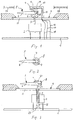
- Fig. 1 shows schematically the basic structure of a device for analog display of measured values, which is arranged for example on the dashboard of a motor vehicle.
- a measuring unit 2 for example a speed or rotational speed measuring unit of a motor vehicle, is attached to a base 1.
- a shaft 3 driven by the measuring mechanism 2 as a function of the measured value carries at its free end a bearing part 4 in which a pointer 5 made of light-conducting material is fastened.
- the pointer 5 consists of a pointer section 6 running into a tip and a hub part 7 connected to it, with which the pointer in the bearing part 4 is supported in a self-supporting manner.
- An obliquely running, light-reflecting surface 8 is formed in the hub part 7.
- the dial 9 is in turn arranged on the top of a dial carrier 11, for example applied by screen printing.
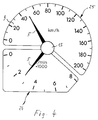
- the dial 9, as can be seen from Fig. 4, is sector-shaped, i.e. the measuring or rotating range of the pointer 5 does not extend over 360, but only over approximately 240 °.
- a cover 13 projecting beyond the hub part 7 of the pointer 5 is fixedly arranged with the aid of a stand 12.
- two light sources 14, 15 - in the form of conventional light-emitting diodes or incandescent lamps - are attached in such a way that the light emerging from them in the axial direction of the pointer 5 directly and essentially centrally into the hub part 7 and from there after corresponding deflection at the reflecting surface 8 into the pointer section 6. In this way, extremely powerful illumination of the pointer 5 is possible.
- the light sources 14, 15 can be connected to a current source via electrical lines 16, 17 and 18.
- two light sources 14, 15 are arranged on the cover 13, which can generate different colored light.
- the pointer 5 can be brightly illuminated with different colors, possibly also mixed colors, with one light source, for example, a smaller speed range, in particular below 50 km / h, and the other Light source can be assigned to a dial area that encompasses higher speeds.
- the light sources 14, 15 are switched over via known electrical scanning and switching means. Instead of different colors, different intensities of the light source could also be used.
- a device of the type shown schematically in FIG. 1 with a transparent cover glass 19 is usually used provided, which is shown schematically and broken off in Fig. 1. It is possible to arrange one or more light sources 14, 15 on the underside of this cover glass 19 with appropriate cover upwards. In this case, the stand 12 supported on the dial support 11 can be omitted.
- the light sources 14, 15 on the side facing away from the dial 9 of the hub part 7 are arranged centrally and directly above this part.
- the shaft 3 driven by the measuring mechanism 2 is designed as a hollow shaft.
- a light guide 21, through which the hub part 7 carrying the pointer section 6 is fastened, runs through this hollow shaft.
- the light guide 21 is rotatably connected to the shaft 3.
- a conically widened end 22 of the light guide 21 protruding from the shaft 3 at the bottom is opposite one or more light sources 23 fastened on the base 1, the light of which in this way in the axial direction of the pointer 5 and centrally directly into the hub part 7 and from there the inclined surface is coupled into the pointer section 6.
- An extremely bright illumination of the pointer 5 can also be achieved in this way.
- a light source to the side of the pointer 5 and immediately below the dial support 11 and to guide the light emerging from this light source in a conventional manner through the support 11 through a light guide and from above Coupling her into the hub part 7 of the pointer 5 centrally and axially.
- FIG. 4 shows a combined dial which comprises two separate scale areas 25, 26 which are assigned to different measured values, namely the driving speed of a motor vehicle or the speed of a motor vehicle engine.
- the scale area 25 corresponds to the dial 9 already mentioned.
- the two scale areas 25, 26 are jointly assigned the pointer 5, which can be rotated centrally above the scale areas 25, 26.
- On the underside of the cover 13, one or more light sources 14, 15 are provided which illuminate the pointer 5 in the manner described.
- the display of measured values on the combined dial having the scale areas 25, 26 takes place in the following manner: the pointer 5, which in this case is not connected to a measuring mechanism 2 and is driven independently of this measured value, rotates in the same direction at a constant rotational speed constantly above the scale areas 25, 26.
- the switch-on phases of the light sources 14, 15 arranged under the cover 13 are controlled as a function of the measured value, so that the pointer 5 is stroboscopically illuminated only over the point of the scale areas 25, 26 corresponding to the measured value to be displayed and is thus visible. Because of the stroboscopic illumination of the pointer 5, it appears to be stationary at the point corresponding to the measured value in question.
- a different color can be provided for the phase-dependent illumination of the pointer 5 within the scale area 25 than in the scale area 26.
Landscapes
- Physics & Mathematics (AREA)
- General Physics & Mathematics (AREA)
- Details Of Measuring Devices (AREA)
Applications Claiming Priority (1)
| Application Number | Priority Date | Filing Date | Title |
|---|---|---|---|
| DE4129976 | 1991-09-10 |
Publications (2)
| Publication Number | Publication Date |
|---|---|
| EP0536485A2 true EP0536485A2 (fr) | 1993-04-14 |
| EP0536485A3 EP0536485A3 (en) | 1993-06-30 |
Family
ID=6440225
Family Applications (1)
| Application Number | Title | Priority Date | Filing Date |
|---|---|---|---|
| EP19920112451 Withdrawn EP0536485A3 (en) | 1991-09-10 | 1992-07-21 | Device for analog display of measuring values |
Country Status (1)
| Country | Link |
|---|---|
| EP (1) | EP0536485A3 (fr) |
Cited By (8)
| Publication number | Priority date | Publication date | Assignee | Title |
|---|---|---|---|---|
| FR2744680A1 (fr) * | 1996-02-14 | 1997-08-14 | Sagem | Tableau de bord a boitier conducteur |
| EP0945710A1 (fr) * | 1998-03-21 | 1999-09-29 | Mannesmann VDO Aktiengesellschaft | Instrument indicateur |
| EP0967464A1 (fr) * | 1998-06-24 | 1999-12-29 | Mannesmann VDO Aktiengesellschaft | Instrument à aiguille |
| EP1077363A3 (fr) * | 1999-08-17 | 2001-09-19 | Mannesmann VDO AG | Instrument d'affichage avec une aiguille |
| FR2859323A1 (fr) * | 2003-08-29 | 2005-03-04 | Sonceboz Sa | Actionneur universel notamment pour application aux tableaux de bord |
| EP1371522A3 (fr) * | 2002-06-11 | 2005-12-21 | Borg Instruments AG | Indicateur à arbre creux |
| DE102005036003A1 (de) * | 2005-08-01 | 2007-02-08 | GM Global Technology Operations, Inc., Detroit | Anzeigeinstrument mit einem Ziffernblatt |
| US7520242B2 (en) * | 2003-09-26 | 2009-04-21 | Microcomponents Sa | Micromotor arrangement for driving a pointer-type indicating device |
Family Cites Families (3)
| Publication number | Priority date | Publication date | Assignee | Title |
|---|---|---|---|---|
| JPS54148158U (fr) * | 1978-04-05 | 1979-10-15 | ||
| US4257084A (en) * | 1979-02-21 | 1981-03-17 | Reynolds Christopher H | Display device |
| DE3626957A1 (de) * | 1986-08-08 | 1988-02-11 | Vdo Schindling | Zeigerinstrument |
-
1992
- 1992-07-21 EP EP19920112451 patent/EP0536485A3/de not_active Withdrawn
Cited By (11)
| Publication number | Priority date | Publication date | Assignee | Title |
|---|---|---|---|---|
| FR2744680A1 (fr) * | 1996-02-14 | 1997-08-14 | Sagem | Tableau de bord a boitier conducteur |
| EP0945710A1 (fr) * | 1998-03-21 | 1999-09-29 | Mannesmann VDO Aktiengesellschaft | Instrument indicateur |
| EP0967464A1 (fr) * | 1998-06-24 | 1999-12-29 | Mannesmann VDO Aktiengesellschaft | Instrument à aiguille |
| US6178917B1 (en) | 1998-06-24 | 2001-01-30 | Mannesmann Vdo Ag | Pointer instrument |
| EP1077363A3 (fr) * | 1999-08-17 | 2001-09-19 | Mannesmann VDO AG | Instrument d'affichage avec une aiguille |
| EP1371522A3 (fr) * | 2002-06-11 | 2005-12-21 | Borg Instruments AG | Indicateur à arbre creux |
| FR2859323A1 (fr) * | 2003-08-29 | 2005-03-04 | Sonceboz Sa | Actionneur universel notamment pour application aux tableaux de bord |
| WO2005022088A1 (fr) * | 2003-08-29 | 2005-03-10 | Sonceboz Sa | Actionneur universel notamment pour application aux tableaux de bord |
| US7503278B2 (en) | 2003-08-29 | 2009-03-17 | Sonceboz Sa | Universal actuator particularly for dashboards |
| US7520242B2 (en) * | 2003-09-26 | 2009-04-21 | Microcomponents Sa | Micromotor arrangement for driving a pointer-type indicating device |
| DE102005036003A1 (de) * | 2005-08-01 | 2007-02-08 | GM Global Technology Operations, Inc., Detroit | Anzeigeinstrument mit einem Ziffernblatt |
Also Published As
| Publication number | Publication date |
|---|---|
| EP0536485A3 (en) | 1993-06-30 |
Similar Documents
| Publication | Publication Date | Title |
|---|---|---|
| DE3817874C2 (de) | Meßgerät | |
| DE3704574C2 (de) | Zifferblatt für ein Messinstrument | |
| DE4300701C2 (de) | Beleuchtete Taste | |
| DE19828041A1 (de) | Zeigerinstrument | |
| EP1399328B1 (fr) | Instrument de signalisation | |
| DE4227106A1 (de) | Fahrzeug-anzeigegeraet | |
| DE4007379A1 (de) | Anzeigevorrichtung | |
| DE68902708T2 (de) | Analoganzeiger mit leuchtzeiger und grenzindikation. | |
| EP0536485A2 (fr) | Dispositif d'afficahge analogique de valeurs de mesure | |
| EP1106419B1 (fr) | Appareil de commande à éléments de commande lumineux | |
| DE69300468T2 (de) | Helligkeits- und farbenveränderbare Armaturenbeleuchtung. | |
| DE19500668A1 (de) | Anzeigeeinrichtung | |
| DE202006019347U1 (de) | Anordnung zur Steuerung einer LED-Rundumkennleuchte | |
| DE19939004A1 (de) | Anzeigeinstrument mit einem Zeiger | |
| DE4244452C2 (de) | Anzeigeinstrument für Kraftfahrzeuge | |
| DE102008004628A1 (de) | Anzeigevorrichtung für ein Kraftfahrzeug | |
| DE102004052893B4 (de) | Zeigerinstrument | |
| EP0990873A1 (fr) | Aiguille de cadran indicateur | |
| DE8902383U1 (de) | Vorrichtung zum Beleuchten der Symbole für die Schaltstellungen des Betätigungsgliedes von Schalteinrichtungen | |
| EP0082509A1 (fr) | Montage des aiguilles d'un dispositif indicateur du temps éclairable par transmission de lumière | |
| WO2005116663A1 (fr) | Instrument indicateur pour vehicule a moteur | |
| DE961757C (de) | Verladeanlage fuer Schuettgut mit Greiferhubwerk | |
| EP1672329B1 (fr) | Instrument pointeur | |
| DE10256183B4 (de) | Drehsteller mit beleuchtetem Symbolring | |
| DE102014004180B4 (de) | Anzeigevorrichtung für ein Kraftfahrzeug |
Legal Events
| Date | Code | Title | Description |
|---|---|---|---|
| PUAI | Public reference made under article 153(3) epc to a published international application that has entered the european phase |
Free format text: ORIGINAL CODE: 0009012 |
|
| AK | Designated contracting states |
Kind code of ref document: A2 Designated state(s): DE ES FR IT PT |
|
| PUAL | Search report despatched |
Free format text: ORIGINAL CODE: 0009013 |
|
| AK | Designated contracting states |
Kind code of ref document: A3 Designated state(s): DE ES FR IT PT |
|
| STAA | Information on the status of an ep patent application or granted ep patent |
Free format text: STATUS: THE APPLICATION IS DEEMED TO BE WITHDRAWN |
|
| 18D | Application deemed to be withdrawn |
Effective date: 19931231 |