EP0536639A1 - Système de freinage pour des camions à frein de service et ralentisseur - Google Patents
Système de freinage pour des camions à frein de service et ralentisseur Download PDFInfo
- Publication number
- EP0536639A1 EP0536639A1 EP92116813A EP92116813A EP0536639A1 EP 0536639 A1 EP0536639 A1 EP 0536639A1 EP 92116813 A EP92116813 A EP 92116813A EP 92116813 A EP92116813 A EP 92116813A EP 0536639 A1 EP0536639 A1 EP 0536639A1
- Authority
- EP
- European Patent Office
- Prior art keywords
- brake
- retarder
- braking
- brake system
- switched
- Prior art date
- Legal status (The legal status is an assumption and is not a legal conclusion. Google has not performed a legal analysis and makes no representation as to the accuracy of the status listed.)
- Granted
Links
Images

Classifications
-
- B—PERFORMING OPERATIONS; TRANSPORTING
- B60—VEHICLES IN GENERAL
- B60T—VEHICLE BRAKE CONTROL SYSTEMS OR PARTS THEREOF; BRAKE CONTROL SYSTEMS OR PARTS THEREOF, IN GENERAL; ARRANGEMENT OF BRAKING ELEMENTS ON VEHICLES IN GENERAL; PORTABLE DEVICES FOR PREVENTING UNWANTED MOVEMENT OF VEHICLES; VEHICLE MODIFICATIONS TO FACILITATE COOLING OF BRAKES
- B60T13/00—Transmitting braking action from initiating means to ultimate brake actuator with power assistance or drive; Brake systems incorporating such transmitting means, e.g. air-pressure brake systems
- B60T13/10—Transmitting braking action from initiating means to ultimate brake actuator with power assistance or drive; Brake systems incorporating such transmitting means, e.g. air-pressure brake systems with fluid assistance, drive, or release
- B60T13/58—Combined or convertible systems
- B60T13/585—Combined or convertible systems comprising friction brakes and retarders
-
- B—PERFORMING OPERATIONS; TRANSPORTING
- B60—VEHICLES IN GENERAL
- B60T—VEHICLE BRAKE CONTROL SYSTEMS OR PARTS THEREOF; BRAKE CONTROL SYSTEMS OR PARTS THEREOF, IN GENERAL; ARRANGEMENT OF BRAKING ELEMENTS ON VEHICLES IN GENERAL; PORTABLE DEVICES FOR PREVENTING UNWANTED MOVEMENT OF VEHICLES; VEHICLE MODIFICATIONS TO FACILITATE COOLING OF BRAKES
- B60T1/00—Arrangements of braking elements, i.e. of those parts where braking effect occurs specially for vehicles
- B60T1/02—Arrangements of braking elements, i.e. of those parts where braking effect occurs specially for vehicles acting by retarding wheels
- B60T1/08—Arrangements of braking elements, i.e. of those parts where braking effect occurs specially for vehicles acting by retarding wheels using fluid or powdered medium
-
- B—PERFORMING OPERATIONS; TRANSPORTING
- B60—VEHICLES IN GENERAL
- B60T—VEHICLE BRAKE CONTROL SYSTEMS OR PARTS THEREOF; BRAKE CONTROL SYSTEMS OR PARTS THEREOF, IN GENERAL; ARRANGEMENT OF BRAKING ELEMENTS ON VEHICLES IN GENERAL; PORTABLE DEVICES FOR PREVENTING UNWANTED MOVEMENT OF VEHICLES; VEHICLE MODIFICATIONS TO FACILITATE COOLING OF BRAKES
- B60T8/00—Arrangements for adjusting wheel-braking force to meet varying vehicular or ground-surface conditions, e.g. limiting or varying distribution of braking force
- B60T8/18—Arrangements for adjusting wheel-braking force to meet varying vehicular or ground-surface conditions, e.g. limiting or varying distribution of braking force responsive to vehicle weight or load, e.g. load distribution
Definitions
- the invention relates to a brake system for commercial vehicles with a service brake and a continuous brake according to the preamble of claim 1.
- Known brake systems for commercial vehicles with service and continuous brakes provide linear parallel retarders which have several braking stages with progressive grading, especially when the vehicle is unladen.
- the rough grading leads to a disadvantageous retarder effect with jerky deceleration of the vehicle when braking, especially when the vehicle is unladen.
- the retarder cannot be connected upstream to the service brake.
- a brake system of the type mentioned which uses a pressure control valve with several pressure relief valves to control the pressure in the retarder.
- the known brake system is comparatively complicated and only suitable in conjunction with a hydrodynamic converter.
- the object of the invention is to provide a brake system of the type mentioned which, with the aid of simple means, enables substantially jerk-free braking operation of leaf-sprung commercial vehicles even when the vehicle is partially or unloaded.
- the essence of the invention is the creation of an electrical switch-off device for the upper braking stages of a multi-stage retarder, in particular in the case of partially or unloaded vehicles with leaf-sprung rear axles and vehicle-fixed, automatically load-dependent brake control valves.
- the deflection position of the control lever of the (already existing) ALB controller is determined by the electrical control device with an inductive sensor within certain, predefinable limits and a corresponding electrical switch-off signal is triggered, which actuates individual switch-off relays that switch off the upper braking stages of the multi-stage brake-operated retarder. This means that a brake-operated retarder does not develop the full braking force when the vehicle is empty or only partially loaded.
- an essentially jerk-free braking operation is set up. This not only improves the driving comfort of the commercial vehicle, but also increases driving safety due to the absence of jerks.
- the (geometric) grading of the retarder is expediently selected. If an electric or hydraulic retarder is switched in six stages, the delay effect of the stages with the percentages 12.5 / 25 / 37.5 / 50/75/100% can be used, for example. Other distributions can also result from optimization.
- the invention therefore overcomes the essential disadvantage of known braking systems, which is seen in the fact that the retarder effect overlaps the service braking effect is and this results in an undesirable progressiveness of the braking effect, especially in the area of small decelerations.
- the retarder effect can be preceded by the service brake, so that the service brake does not apply additively until the retarder is fully effective, possibly with a slight overlap (retarders and service brakes act on the same wheels in this view; as a rule, the rear axle).
- the retarder effect can be reduced when the vehicle is empty (if necessary also with partial load) so that not all stages are used, but only the first four braking stages, for example , which reduces the maximum retarder braking effect to approx. 50% or the like. corresponds.
- This can either be achieved by connecting the sensors directly to the brake pressure of the rear axle, which is reduced by the ALB, or by manipulating the electronics if the retarder is controlled by a potentiometer located in the motor vehicle brake valve.
- the retarder can also be stepped up or down steplessly by means of a potentiometer in the motor vehicle brake valve.
- the limitation of the maximum effect is also possible here by appropriate intervention in the control electronics.
- DE-OS 2 023 880 discloses a braking system for commercial vehicles with service and continuous braking in the form of a retarder, which is regulated as a function of the load on the vehicle.
- a retarder which is regulated as a function of the load on the vehicle.
- the vehicle must have air-sprung axles.
- the brake system is generally not suitable for leaf-sprung axles. Otherwise, the known retarder cannot be switched off in its upper braking stages, as is the case with the generic braking system.
- the upper braking stages of the retarder can be switched off.
- the switch-off takes place by means of a cam switch, while a structurally simplified inductive sensor is used in the invention.
- no ALB controller is used, rather an additional mechanical lever switch of comparatively complicated construction, which is also cost-intensive.
- the known upper braking stages can be switched off progressively when larger deflection values of the control lever are exceeded, and the electrical control device has a switch-off relay for the braking stage of the retarder to be switched off, as is the case with the invention in accordance with the features of subclaims 2 and 4.
- the invention proposes (similarly to EP 0 361 708 A2) in a further development a brake system with an electronically controlled brake system, in which the braking deceleration is preferably predetermined by actuating the brake pedal becomes.
- the electronically controlled braking system is controlled in such a way that the retarder is used for braking to its maximum effect and the service brake is only used when there is a higher deceleration requirement, in this case the service brake of the front axle and the rear axle, whereas in the first-mentioned design variants the brake of the front axle remains unaffected in its effect.
- the service brake is automatically and imperceptibly readjusted if the retarder effect declines (for example due to heat fading).
- the electronically controlled brake system in particular, it can be programmed that, for example, every tenth braking is carried out by the service brake alone (without a retarder) in order to ensure the full functionality of the brake pads over the long term.
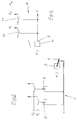
- a brake system (1) for the leaf-sprung rear axle (10) of a commercial vehicle basically provides a vehicle-specific, automatically load-dependent brake control valve, a so-called ALB controller (3), the control lever (4) of which is connected via a linkage (not shown), e.g. with the sensor rod between the first and the second rear axle (10) of a double-axle unit is connected.
- the control lever (3) is more or less deflected in its swivel position.
- the pressure output (7) of the ALB controller (3) is connected to the brake cylinders of the rear axle (10) via a brake line (12).
- a reduced braking pressure is thus applied to the rear axle (10).
- the brake line (12) or the pressure output (7) of the ALB controller (3) is also connected via a pressure switch control (8) to the individual braking stages (R1, R2, ... R6), with each braking stage Pressure switch (13) with different pressure switching characteristics is assigned.
- the retarder is therefore increasingly put into operation with increasing brake pressure.
- the retarder effect when the vehicle is empty can be reduced in such a way that not all stages are used, but rather, for example, according to the variant of FIG. 1 the last two retarder brake stages (R5, R6) are switched off. It is switched off by an electrical control device (2) with an inductive sensor (5), which can be actuated as a function of the deflection position of the regulator lever (4) of the ALB regulator (3). Electrical switch-off signals actuate in particular the switch-off relay (6) of the fifth and / or the sixth brake stage (R5, R6) of the retarder.
- Switching off takes place, for example, at a rear axle load of 25 to 50% of the maximum load if six retarder braking levels are provided.
- retarders that have only four switching stages, for example with electrical retarders or eddy current brakes, either the last one, i.e. the fourth stage or the last two, i.e. the third and fourth stages are switched off.
- the inductive sensor (5) can also be a different type of sensor. It does not necessarily have to lie in the area of the control lever (4), but can also act on an adjacent linkage which is pre-coupled to the control lever (4).
- the arrangement of a sensor on the sensor rod between the first and second rear axles of a double-axle unit is also conceivable.
- the embodiment variant according to FIGS. 2 and 3 provides an electrical control device (2) for switching off the upper braking stages (R5, R6) as in the embodiment of FIG. 1.
- the pressure switch control (8) for commissioning the individual brake levels (R1, R2 ...) of the retarder directly connected to the output of a motor vehicle brake valve (11).
- the retarder of the service brake can be continuously switched on or off using a potentiometer in the motor vehicle brake valve. The limitation of the maximum effect is possible by appropriate intervention in the control electronics.
Landscapes
- Engineering & Computer Science (AREA)
- Transportation (AREA)
- Mechanical Engineering (AREA)
- Regulating Braking Force (AREA)
- Hydraulic Control Valves For Brake Systems (AREA)
Applications Claiming Priority (4)
| Application Number | Priority Date | Filing Date | Title |
|---|---|---|---|
| DE4133430 | 1991-10-09 | ||
| DE4133430 | 1991-10-09 | ||
| DE4229222 | 1992-09-02 | ||
| DE4229222A DE4229222A1 (de) | 1991-10-09 | 1992-09-02 | Bremsanlage fuer nutzkraftwagen mit betriebs- und dauerbremse |
Publications (2)
| Publication Number | Publication Date |
|---|---|
| EP0536639A1 true EP0536639A1 (fr) | 1993-04-14 |
| EP0536639B1 EP0536639B1 (fr) | 1995-12-20 |
Family
ID=25908073
Family Applications (1)
| Application Number | Title | Priority Date | Filing Date |
|---|---|---|---|
| EP92116813A Expired - Lifetime EP0536639B1 (fr) | 1991-10-09 | 1992-10-01 | Système de freinage pour des camions à frein de service et ralentisseur |
Country Status (3)
| Country | Link |
|---|---|
| EP (1) | EP0536639B1 (fr) |
| DE (2) | DE4229222A1 (fr) |
| ES (1) | ES2082315T3 (fr) |
Families Citing this family (1)
| Publication number | Priority date | Publication date | Assignee | Title |
|---|---|---|---|---|
| DE10144302A1 (de) * | 2001-09-10 | 2003-06-12 | Knorr Bremse Systeme | Bremsvorrichtung für Fahrzeuge, die eine Betriebsbremsanlage und eine Dauerbremsanlage aufweisen |
Citations (5)
| Publication number | Priority date | Publication date | Assignee | Title |
|---|---|---|---|---|
| FR2108951A1 (fr) * | 1970-10-22 | 1972-05-26 | Labavia | |
| FR2312389A1 (fr) * | 1975-05-27 | 1976-12-24 | Labavia | Dispositif d'asservissement d'un ralentisseur a courants de foucault a la charge du vehicule |
| GB2018374A (en) * | 1978-04-08 | 1979-10-17 | Zahnradfabrik Friedrichshafen | Conjoint control of a hydrodynamic brake and a change-speed gearbox |
| FR2498142A1 (fr) * | 1981-01-22 | 1982-07-23 | Bosch Gmbh Robert | Dispositif de commande de frein retardateur, en particulier pour vehicules utilitaires lourds |
| EP0361708A2 (fr) * | 1988-09-30 | 1990-04-04 | Ford Motor Company Limited | Contrôle pour système de freinage régénératif |
-
1992
- 1992-09-02 DE DE4229222A patent/DE4229222A1/de not_active Withdrawn
- 1992-10-01 DE DE59204749T patent/DE59204749D1/de not_active Expired - Fee Related
- 1992-10-01 ES ES92116813T patent/ES2082315T3/es not_active Expired - Lifetime
- 1992-10-01 EP EP92116813A patent/EP0536639B1/fr not_active Expired - Lifetime
Patent Citations (5)
| Publication number | Priority date | Publication date | Assignee | Title |
|---|---|---|---|---|
| FR2108951A1 (fr) * | 1970-10-22 | 1972-05-26 | Labavia | |
| FR2312389A1 (fr) * | 1975-05-27 | 1976-12-24 | Labavia | Dispositif d'asservissement d'un ralentisseur a courants de foucault a la charge du vehicule |
| GB2018374A (en) * | 1978-04-08 | 1979-10-17 | Zahnradfabrik Friedrichshafen | Conjoint control of a hydrodynamic brake and a change-speed gearbox |
| FR2498142A1 (fr) * | 1981-01-22 | 1982-07-23 | Bosch Gmbh Robert | Dispositif de commande de frein retardateur, en particulier pour vehicules utilitaires lourds |
| EP0361708A2 (fr) * | 1988-09-30 | 1990-04-04 | Ford Motor Company Limited | Contrôle pour système de freinage régénératif |
Also Published As
| Publication number | Publication date |
|---|---|
| EP0536639B1 (fr) | 1995-12-20 |
| DE4229222A1 (de) | 1993-04-15 |
| DE59204749D1 (de) | 1996-02-01 |
| ES2082315T3 (es) | 1996-03-16 |
Similar Documents
| Publication | Publication Date | Title |
|---|---|---|
| EP1528997B1 (fr) | Dispositif de freinage integre pour motos | |
| EP0824433B1 (fr) | Generateur de valeur de reference | |
| DE3410083C3 (de) | Blockiergeschützte hydraulische Bremsanlage für Kraftfahrzeuge | |
| EP0520147A1 (fr) | Dispositif de commande volontaire de montée ou de descente de la carrosserie de véhicules à suspension pneumatique | |
| EP0733532B1 (fr) | Procédé de détermination de la pression de déclenchement d'un frein actionné par pression dans un système de freinage de véhicule | |
| EP3790748B1 (fr) | Système de commande de ressorts pneumatiques ainsi que véhicule muni dudit système et procédé afférent | |
| EP0309697B1 (fr) | Système de freinage pour tracteur pour remorquer un avion | |
| EP0447750A1 (fr) | Système de freinage avec au moins un circuit de freinage | |
| DE102018112846A1 (de) | Steuereinrichtung und Verfahren für die Ansteuerung eines Aktuators zur Betätigung von Bremsmitteln eines Fahrzeuges, insbesondere eines Schienenfahrzeuges | |
| DE19920096B4 (de) | Vorrichtung zur Bremslichtansteuerung | |
| EP0949130B2 (fr) | Dispositif de commande d'un système de freinage de véhicule | |
| EP3900991A1 (fr) | Procédé de commande d'une installation pneumatique de freinage d'une remorque | |
| DE19707210C5 (de) | Verfahren zur achslastabhängigen Bremskraftverteilung in einer Bremsanlage eines Fahrzeuges | |
| EP0733531B1 (fr) | Procédé de freinage d'un véhicule | |
| DE102007056146A1 (de) | Bremsanlage für ein Schienenfahrzeug und Verfahren zum Abbremsen des Schienenfahrzeugs und Bremssteuerung für eine derartige Bremsanlage | |
| EP0956983B1 (fr) | Dispositif de commande de fonctions d'un véhicule | |
| WO1998043858A1 (fr) | Procede et dispositif pour determiner une grandeur representant la vitesse d'un vehicule | |
| DE3013702A1 (de) | Einrichtung zur steuerung von verlangsamungsvorrichtungen | |
| DE2625713A1 (de) | Zweikreisbremsanlage fuer kraftfahrzeuge | |
| EP0536639B1 (fr) | Système de freinage pour des camions à frein de service et ralentisseur | |
| DE19625341C5 (de) | Bremsanlage für Fahrzeuge | |
| DE3318020A1 (de) | Zweikreisbremsanlage fuer fahrzeuge | |
| DE102013008655B4 (de) | Verfahren zur Niveauregelung eines luftgefederten Kraftfahrzeugs | |
| DE4034351C2 (fr) | ||
| DE19739984B4 (de) | Verfahren zur Abbremsung eines Fahrzeuges |
Legal Events
| Date | Code | Title | Description |
|---|---|---|---|
| PUAI | Public reference made under article 153(3) epc to a published international application that has entered the european phase |
Free format text: ORIGINAL CODE: 0009012 |
|
| AK | Designated contracting states |
Kind code of ref document: A1 Designated state(s): DE ES FR GB IT NL |
|
| 17P | Request for examination filed |
Effective date: 19930910 |
|
| 17Q | First examination report despatched |
Effective date: 19940513 |
|
| GRAA | (expected) grant |
Free format text: ORIGINAL CODE: 0009210 |
|
| AK | Designated contracting states |
Kind code of ref document: B1 Designated state(s): DE ES FR GB IT NL |
|
| ITF | It: translation for a ep patent filed | ||
| REF | Corresponds to: |
Ref document number: 59204749 Country of ref document: DE Date of ref document: 19960201 |
|
| ET | Fr: translation filed | ||
| REG | Reference to a national code |
Ref country code: ES Ref legal event code: FG2A Ref document number: 2082315 Country of ref document: ES Kind code of ref document: T3 |
|
| GBT | Gb: translation of ep patent filed (gb section 77(6)(a)/1977) |
Effective date: 19960326 |
|
| PLBE | No opposition filed within time limit |
Free format text: ORIGINAL CODE: 0009261 |
|
| 26N | No opposition filed | ||
| PGFP | Annual fee paid to national office [announced via postgrant information from national office to epo] |
Ref country code: GB Payment date: 19990924 Year of fee payment: 8 |
|
| PGFP | Annual fee paid to national office [announced via postgrant information from national office to epo] |
Ref country code: ES Payment date: 19991018 Year of fee payment: 8 |
|
| PGFP | Annual fee paid to national office [announced via postgrant information from national office to epo] |
Ref country code: NL Payment date: 19991029 Year of fee payment: 8 Ref country code: FR Payment date: 19991029 Year of fee payment: 8 Ref country code: DE Payment date: 19991029 Year of fee payment: 8 |
|
| PG25 | Lapsed in a contracting state [announced via postgrant information from national office to epo] |
Ref country code: GB Free format text: LAPSE BECAUSE OF NON-PAYMENT OF DUE FEES Effective date: 20001001 |
|
| PG25 | Lapsed in a contracting state [announced via postgrant information from national office to epo] |
Ref country code: ES Free format text: LAPSE BECAUSE OF NON-PAYMENT OF DUE FEES Effective date: 20001002 |
|
| PG25 | Lapsed in a contracting state [announced via postgrant information from national office to epo] |
Ref country code: NL Free format text: LAPSE BECAUSE OF NON-PAYMENT OF DUE FEES Effective date: 20010501 |
|
| GBPC | Gb: european patent ceased through non-payment of renewal fee |
Effective date: 20001001 |
|
| PG25 | Lapsed in a contracting state [announced via postgrant information from national office to epo] |
Ref country code: FR Free format text: LAPSE BECAUSE OF NON-PAYMENT OF DUE FEES Effective date: 20010629 |
|
| NLV4 | Nl: lapsed or anulled due to non-payment of the annual fee |
Effective date: 20010501 |
|
| PG25 | Lapsed in a contracting state [announced via postgrant information from national office to epo] |
Ref country code: DE Free format text: LAPSE BECAUSE OF NON-PAYMENT OF DUE FEES Effective date: 20010703 |
|
| REG | Reference to a national code |
Ref country code: FR Ref legal event code: ST |
|
| REG | Reference to a national code |
Ref country code: ES Ref legal event code: FD2A Effective date: 20011113 |
|
| PG25 | Lapsed in a contracting state [announced via postgrant information from national office to epo] |
Ref country code: IT Free format text: LAPSE BECAUSE OF NON-PAYMENT OF DUE FEES;WARNING: LAPSES OF ITALIAN PATENTS WITH EFFECTIVE DATE BEFORE 2007 MAY HAVE OCCURRED AT ANY TIME BEFORE 2007. THE CORRECT EFFECTIVE DATE MAY BE DIFFERENT FROM THE ONE RECORDED. Effective date: 20051001 |