EP0536683B1 - Appareil de guidage d'un rayon laser - Google Patents
Appareil de guidage d'un rayon laser Download PDFInfo
- Publication number
- EP0536683B1 EP0536683B1 EP92117015A EP92117015A EP0536683B1 EP 0536683 B1 EP0536683 B1 EP 0536683B1 EP 92117015 A EP92117015 A EP 92117015A EP 92117015 A EP92117015 A EP 92117015A EP 0536683 B1 EP0536683 B1 EP 0536683B1
- Authority
- EP
- European Patent Office
- Prior art keywords
- laser beam
- guiding
- reflecting surface
- supporting drum
- beam according
- Prior art date
- Legal status (The legal status is an assumption and is not a legal conclusion. Google has not performed a legal analysis and makes no representation as to the accuracy of the status listed.)
- Revoked
Links
Images

Classifications
-
- B—PERFORMING OPERATIONS; TRANSPORTING
- B23—MACHINE TOOLS; METAL-WORKING NOT OTHERWISE PROVIDED FOR
- B23K—SOLDERING OR UNSOLDERING; WELDING; CLADDING OR PLATING BY SOLDERING OR WELDING; CUTTING BY APPLYING HEAT LOCALLY, e.g. FLAME CUTTING; WORKING BY LASER BEAM
- B23K26/00—Working by laser beam, e.g. welding, cutting or boring
- B23K26/08—Devices involving relative movement between laser beam and workpiece
- B23K26/083—Devices involving movement of the workpiece in at least one axial direction
- B23K26/0838—Devices involving movement of the workpiece in at least one axial direction by using an endless conveyor belt
- B23K26/0846—Devices involving movement of the workpiece in at least one axial direction by using an endless conveyor belt for moving elongated workpieces longitudinally, e.g. wire or strip material
-
- B—PERFORMING OPERATIONS; TRANSPORTING
- B23—MACHINE TOOLS; METAL-WORKING NOT OTHERWISE PROVIDED FOR
- B23K—SOLDERING OR UNSOLDERING; WELDING; CLADDING OR PLATING BY SOLDERING OR WELDING; CUTTING BY APPLYING HEAT LOCALLY, e.g. FLAME CUTTING; WORKING BY LASER BEAM
- B23K26/00—Working by laser beam, e.g. welding, cutting or boring
- B23K26/02—Positioning or observing the workpiece, e.g. with respect to the point of impact; Aligning, aiming or focusing the laser beam
- B23K26/06—Shaping the laser beam, e.g. by masks or multi-focusing
-
- B—PERFORMING OPERATIONS; TRANSPORTING
- B23—MACHINE TOOLS; METAL-WORKING NOT OTHERWISE PROVIDED FOR
- B23K—SOLDERING OR UNSOLDERING; WELDING; CLADDING OR PLATING BY SOLDERING OR WELDING; CUTTING BY APPLYING HEAT LOCALLY, e.g. FLAME CUTTING; WORKING BY LASER BEAM
- B23K26/00—Working by laser beam, e.g. welding, cutting or boring
- B23K26/02—Positioning or observing the workpiece, e.g. with respect to the point of impact; Aligning, aiming or focusing the laser beam
- B23K26/06—Shaping the laser beam, e.g. by masks or multi-focusing
- B23K26/064—Shaping the laser beam, e.g. by masks or multi-focusing by means of optical elements, e.g. lenses, mirrors or prisms
-
- B—PERFORMING OPERATIONS; TRANSPORTING
- B23—MACHINE TOOLS; METAL-WORKING NOT OTHERWISE PROVIDED FOR
- B23K—SOLDERING OR UNSOLDERING; WELDING; CLADDING OR PLATING BY SOLDERING OR WELDING; CUTTING BY APPLYING HEAT LOCALLY, e.g. FLAME CUTTING; WORKING BY LASER BEAM
- B23K26/00—Working by laser beam, e.g. welding, cutting or boring
- B23K26/02—Positioning or observing the workpiece, e.g. with respect to the point of impact; Aligning, aiming or focusing the laser beam
- B23K26/06—Shaping the laser beam, e.g. by masks or multi-focusing
- B23K26/064—Shaping the laser beam, e.g. by masks or multi-focusing by means of optical elements, e.g. lenses, mirrors or prisms
- B23K26/0643—Shaping the laser beam, e.g. by masks or multi-focusing by means of optical elements, e.g. lenses, mirrors or prisms comprising mirrors
-
- B—PERFORMING OPERATIONS; TRANSPORTING
- B23—MACHINE TOOLS; METAL-WORKING NOT OTHERWISE PROVIDED FOR
- B23K—SOLDERING OR UNSOLDERING; WELDING; CLADDING OR PLATING BY SOLDERING OR WELDING; CUTTING BY APPLYING HEAT LOCALLY, e.g. FLAME CUTTING; WORKING BY LASER BEAM
- B23K26/00—Working by laser beam, e.g. welding, cutting or boring
- B23K26/02—Positioning or observing the workpiece, e.g. with respect to the point of impact; Aligning, aiming or focusing the laser beam
- B23K26/06—Shaping the laser beam, e.g. by masks or multi-focusing
- B23K26/064—Shaping the laser beam, e.g. by masks or multi-focusing by means of optical elements, e.g. lenses, mirrors or prisms
- B23K26/0648—Shaping the laser beam, e.g. by masks or multi-focusing by means of optical elements, e.g. lenses, mirrors or prisms comprising lenses
-
- B—PERFORMING OPERATIONS; TRANSPORTING
- B23—MACHINE TOOLS; METAL-WORKING NOT OTHERWISE PROVIDED FOR
- B23K—SOLDERING OR UNSOLDERING; WELDING; CLADDING OR PLATING BY SOLDERING OR WELDING; CUTTING BY APPLYING HEAT LOCALLY, e.g. FLAME CUTTING; WORKING BY LASER BEAM
- B23K26/00—Working by laser beam, e.g. welding, cutting or boring
- B23K26/02—Positioning or observing the workpiece, e.g. with respect to the point of impact; Aligning, aiming or focusing the laser beam
- B23K26/06—Shaping the laser beam, e.g. by masks or multi-focusing
- B23K26/0665—Shaping the laser beam, e.g. by masks or multi-focusing by beam condensation on the workpiece, e.g. for focusing
Definitions
- the invention relates to a device for guiding a laser beam.
- Lasers are used in numerous industrial applications to process various materials; for example, lasers in the paper processing sector are used to cut or perforate paper.
- the properties of the laser beam are subject to the highest demands.
- These requirements are found in the devices used to generate and guide the laser beam.
- the requirements with regard to laser beam movements i.e. its position, course, direction and speed of movement are difficult to meet. This is because the deflection or guidance of a laser beam and, as a rule, its focusing can only be done with the help of moving components that deflect, guide or focus the laser beam through their own movement.
- a device for guiding a laser beam which has the features of the preamble of claim 1.
- a reflective surface is arranged on a cylindrical carrier roller, which extends along a spiral path on the outer surface of the carrier roller and projects radially from the outer surface of the carrier roller.
- the device is part of a laser printer or a copier.
- the laser beam is directed onto the spiral mirror and from there is reflected onto the image drum.
- the carrier roller rotates, the laser beam scans the surface of the image drum along a surface line parallel to the axis of the image drum. If the image drum is also rotated, the entire image drum surface is scanned line by line.
- the invention has for its object to develop a device for guiding a laser beam with the features of the upper handle of claim 1 so that the above-described inclination is avoided.
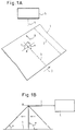
- FIGS. 1A and 1B show a paper web 1 which is moved in the direction of arrow 2 during processing.
- perforations 3 are introduced into the paper web 1 at predetermined intervals from one another, as is the case, for example, in the production of continuous forms.
- the processing, ie the introduction of the perforation 3, takes place with the aid of a laser beam 4, which is emitted by a laser light source 5.
- the laser beam 4 strikes the paper web 1 at the impact point A and introduces the perforation cut into the paper web.
- the laser beam 4 is preferably perpendicular to the plane of the paper web 1, so that both the angle alpha and the angle beta are 90 °. This ensures that the cutting length of the laser beam 4 in the paper is minimal.
- the laser beam 4 is in the direction of arrow 6, i.e. moved transversely to the direction of movement 2 of the paper web. During the entire movement of the laser beam 4 from one edge to the other edge of the paper web 1, completely uniform processing can only be achieved if the angles alpha and beta remain unchanged, i.e. the laser beam 4 is perpendicular to the plane of the paper web 1 during the entire movement.
- the problems described below with reference to FIG. 1B arise for various reasons. If namely the laser beam 4, which is emitted by the laser light source 5, is deflected at the deflection point B with the aid of tilting or polygon mirrors to the paper web 1, the angle alpha is 90 ° only in the middle position of the laser beam. In all other positions, the laser beam is inclined to the plane of the paper web 1, so that the angle alpha deviates from the value 90 °. The deviation is greatest at the two edges of the paper web due to the system. In addition, the path that the laser beam has to travel from deflection point B to paper web 1 also changes depending on the course of the laser beam.
- the inclination of the laser beam is avoided with regard to the angle alpha and an incidence which is always perpendicular to the plane of the paper web is ensured.
- the laser beam guiding device is constructed from a cylindrical carrier roller 10, on the outer surface of which a reflective surface 11 is spirally attached.
- the reflecting surface 11 protrudes essentially radially from the outer surface of the carrier roller 10, but is inclined in some areas with respect to the radial alignment, which is explained in more detail in connection with FIG. 5.
- the area 11 is at the embodiment shown in Fig. 2 part of a tape 12 which is wound around the outer surface of the cylindrical support roller 10 and attached thereto. 2, the reflecting surface 11 is subdivided into individual segments, but this subdivision primarily serves to improve the perspective representation of the spatial relationships.
- the reflective surface 11 of the spirally wound tape 12 is continuous unless the intended application requires segmentation of the reflective surface.
- the reflecting surface 11 serves to guide or deflect a laser beam which is incident essentially parallel to the axis of rotation of the roller 10 and runs close to the surface of the jacket. If the roller 10 rotates about its longitudinal axis, the deflection point of the laser beam travels along the reflecting surface 11.
- the deflected laser beam shifts in accordance with the migration of the incident laser beam on the reflecting surface 11, depending on its configuration.
- the incident laser beam can always be deflected such that the deflected laser beam shifts in parallel.
- a laser beam incident perpendicularly to the paper web to be processed can thus be moved transversely to the paper web with the aid of the laser beam guiding device according to the invention without the vertical alignment of the laser beam to the plane of the paper web having to be given up with regard to the angle alpha.
- the deflection speed depends essentially on the rotation speed of the carrier roller 10. Because of the almost rotationally symmetrical distribution of the masses, a very high rotation speed of the roller 10 and therefore a very high displacement speed of the deflected laser beam can be achieved.
- the laser beam is also reset almost without delay, since the laser beam is suddenly returned when the laser beam passes from the end 11a to the end 11b of the reflecting surface 11.
- FIGS. 3A and 3B in which the carrier roller 10 and the reflecting surface 11 are only shown schematically.
- Fig. 3A shows a first rotational position of the roller 10, which is essentially the position of the roller in the 2 corresponds to the perspective representation of FIG. 3B shows a further, more advanced rotational position of the roller 10.
- the laser beam 4 incident parallel to the axis of rotation is shown, which runs close to the lateral surface of the carrier roller 10 and which is emitted by a laser light source 5.
- the laser beam 4 strikes the reflecting surface 11 at the deflection point B and is deflected from there in the direction of the paper web 1.
- the angle gamma which the reflecting surface 11 in the schematic representation of FIGS. 3A and 3B makes with the upper surface line of the roller 10, is preferably 45 °, in particular when the laser beam 4 runs parallel to the axis of rotation of the cylindrical roller 10.
- the laser beam 4 is deflected by the reflecting surface 11 at the deflection point B so that it strikes the paper web 1 perpendicularly at the point of incidence A.
- the angle alpha between the laser beam 4 and the plane of the paper web 1 is 90 °.
- the deflection point B shifts on the reflecting surface 11 such that the deflected laser beam and its point of incidence A move in the direction of the arrow 6.
- the vertical beam guidance of the deflected laser beam is retained so that the angle alpha is still 90 °.
- the deflected Laser beam moved in parallel from one edge to the other edge of the paper web 1 without the angle of incidence alpha changing. Since the laser beam thus always strikes the paper web 1 perpendicularly, the depth of cut in the paper is not influenced by the shift in the direction of the arrow 6, so that the processing can be carried out with constant laser power and uniform cuts can be achieved.
- the path length of the deflected laser beam remains unaffected, since it corresponds at all times to the height h of the deflection point B above the plane of the paper web 1.
- a semi-cylindrical collecting lens can be used to focus the laser beam, which is attached parallel to the axis of rotation of the carrier roller 10 below it so that the deflected laser beam always passes through it.
- a possible position of the lens L is indicated in FIG. 3B. Due to the uniform parallel displacement of the deflected laser beam, the lens L for focusing the laser beam can have the very simple semi-cylindrical structure. Furthermore, simple masks for influencing the laser beam can also be provided in the area of the lens L.
- the laser light is focused without adding a lens arrangement.
- a spiral belt 12 is attached to the carrier roller 10, the reflecting surface 11 of which is designed as a concave mirror.
- the curved, reflecting surface 11 bundles the laser light and focuses it on the plane of the paper web 1.
- the focusing can be constant over the entire
- the length of the spiral belt 12 or sections may be different. This arrangement allows the focus to be easily adapted to the requirements imposed by the desired processing.
- 5 shows the essential aspect of the invention, according to which the reflecting surface 11 protrudes radially from the jacket surface only in some areas. In other areas, the reflective surface 11 is inclined with respect to the radial alignment. 5 shows three positions of the reflecting surface 11, of which the middle is radially aligned and two are inclined to it. The inclination of the reflective surface 11 preferably changes continuously; however, it can also be constant in sections. The inclined arrangement of the reflecting surface 11 leads to a deflection of the laser beam, which is described in more detail below.
- this movement of the deflected laser beam 4 can thereby be achieved be that the reflective surface 11 does not run radially to the surface of the surface of the carrier roller 10, but its position changes continuously with respect to a radial orientation.
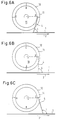
- FIGS. 6A, 6B and 6C different rotary positions of the roller 10 are shown in FIGS. 6A, 6B and 6C.
- the reflective surface 11 of the spiral band 12 is inclined so that the deflected laser beam 4 is opposite to the direction of the arrow 2, i.e. is deflected against the direction of movement of the paper web 1.
- the angle beta is less than 90 °; its smallest value should not fall below 65 °, otherwise the cutting depth in the paper increases too much. If the carrier roller 10 is rotated, the deflected laser beam 4 changes its position continuously and reaches the position which is shown in FIG. 6B. The deflected laser beam 4 strikes the paper web 1 perpendicularly, i.e. the angle beta is 90 °.
- the position of the reflecting surface 11 changes continuously so that the deflected laser beam 4 finally assumes the position shown in FIG. 6C.
- the deflected laser beam 4 strikes the paper web 1 at an angle beta which is greater than 90 °.
- the maximum value of the angle beta should not exceed 115 ° in order not to make the cutting depth in the paper too great.
- the speed of rotation and the continuous change in the angle of the surface normal to the longitudinal line of symmetry of the reflecting surface 11 with the paper web 1 determine the speed at which the deflected laser beam 4 from the initial position approximately 6A, over the vertical position, according to FIG. 6B, into the end position, approximately according to FIG. 6C, moved.
- the angle beta deviates from the desired vertical alignment in the previously described type of laser beam guidance and covers a range of preferably 65 to 115 °. However, these changes and the associated lengthening of the cut length in the paper are tolerable. Because by leading or lagging the laser beam, i.e. by adapting the deflected laser beam to the movement of the paper web, it is possible to process a paper web in motion without the need to slow down or stop the paper web.
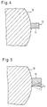
- continuous focusing can be carried out with the aid of a concave mirror-like configuration of the reflecting surface 11, as shown, for example, in FIG. 4. Since the distance between the deflection point B on the reflecting surface 11 and the point of impact A on the paper web 1 changes continuously due to the inclination of the deflected laser beam 4, the focal point distance of the concave mirror-like reflecting surface 11 is advantageously suitably adapted so that the deflected laser beam 4 is always focused on the paper web 1.
- a 500 mm wide roller with a circumference of 1000 mm was manufactured. Two spiral strips with a height and width of 10 mm each were attached to this roller such that the angle between the spiral strip and the longitudinal axis of the mirror was 45 °. Of the Angle of the surface normal to the longitudinal line of symmetry of the reflecting surface of the spiral tape with the paper web was variable between 75 and 105 ° in the longitudinal direction of the cylinder in order to be caused by a resulting. Tracking the deflected laser beam to compensate for the feed motion of the paper. The focal length of the reflecting surface on the spiral band was 250 mm with deviations less than 50 ⁇ m. The deflection of the deflected laser beam in the focal plane was less than 50 ⁇ m. Carrier roller and spiral belts were made of 98% pure Cu.
- the carrier roller and the spiral belts were produced in one piece from a cylindrical raw body in order to ensure that the spiral belt bears completely tension-free on the roller.
- a not inconsiderable thermal load occurs, which leads to material stresses.
- the embodiment described at the outset can be used, in which the roller and spiral belt are manufactured separately.
- the roller is preferably mounted in vibration-damped needle bearings in order to prevent deviations from the required accuracy of the beam guidance. Furthermore, the roller is preferably driven by an infinitely variable gear, the adaptation to the speed of the passing web of material taking place by scanning the web.
- the distance between the recording of the controlled variable and the location of the laser beam movement across the material web should be kept as short as possible for materials with a low modulus of elasticity in order to eliminate the effects of oscillation within the material web in the direction of travel.
- the location of the controlled variable receptacle was approximately 40 cm in front of the location at which the laser beam was guided over the paper web.
- a high-resolution speedometer gave the controlled variable for controlling the gear for the carrier roller.
Landscapes
- Physics & Mathematics (AREA)
- Optics & Photonics (AREA)
- Engineering & Computer Science (AREA)
- Plasma & Fusion (AREA)
- Mechanical Engineering (AREA)
- Laser Beam Processing (AREA)
- Lasers (AREA)
- Laser Surgery Devices (AREA)
- Lenses (AREA)
Claims (15)
- Dispositif destiné à guider un rayon laser, notamment à dévier un rayon laser lors du traitement d'une nappe de matériau, le dispositif comportant- un rouleau porteur (10) cylindrique, et- au moins une surface réfléchissante (11)caractérisé en ce que la surface réfléchissante (11) est inclinée relativement à l'orientation radiale.-- qui s'étend sur la surface périphérique du rouleau porteur (10), le long d'une trajectoire de forme hélicoïdale, et-- qui fait saillie sensiblement de manière radiale hors de la surface périphérique du rouleau porteur (10),
- Dispositif destiné à guider un rayon laser selon la revendication 1, caractérisé en ce que l'inclinaison a une valeur comprise entre -25° et +25 °.
- Dispositif destiné à guider un rayon laser selon la revendication 1 ou 2, caractérisé en ce que la trajectoire de forme hélicoïdale forme un angle de 45 ° avec l'axe longitudinal du rouleau porteur (10).
- Dispositif destiné à guider un rayon laser selon l'une des revendications 1 à 3, caractérisé en ce que la surface réfléchissante (11) s'étend sur un tour autour du rouleau porteur (10).
- Dispositif destiné à guider un rayon laser selon l'une des revendications 1 à 4, caractérisé en ce que la surface réfléchissante (11) débute au niveau de l'une des faces frontales du rouleau porteur (10) et se termine au niveau de l'autre face frontale du rouleau porteur (10).
- Dispositif destiné à guider un rayon laser selon l'une des revendications 1 à 5, caractérisé en ce que la surface réfléchissante (11) fait partie d'une bande (12) agencée en forme d'hélice et disposée sur la surface périphérique du rouleau porteur (10).
- Dispositif destiné à guider un rayon laser selon l'une des revendications 1 à 5, caractérisé en ce que la surface réfléchissante (11) est formée d'un seul tenant avec le rouleau porteur (10).
- Dispositif destiné à guider un rayon laser selon l'une des revendications 1 à 7, caractérisé en ce que la surface réfléchissante (11) est réalisée sous forme de miroir concave pour focaliser le rayon laser.
- Dispositif destiné à guider un rayon laser selon l'une des revendications 1 à 8, caractérisé en ce que la surface réfléchissante (11) est de configuration continue.
- Dispositif destiné à guider un rayon laser selon l'une des revendications 1 à 9, caractérisé en ce que la surface réfléchissante (11) est de configuration segmentée.
- Dispositif destiné à guider un rayon laser selon l'une des revendications 1 à 10, caractérisé en ce que le rouleau porteur (10) est monté dans des roulements à aiguilles à amortissement des vibrations.
- Dispositif destiné à guider un rayon laser selon l'une des revendications 1 à 11, caractérisé en ce que le rouleau porteur (10) est entraîné par une transmission réglable en continu.
- Dispositif de traitement à laser comprenant un dispositif destiné à guider un rayon laser selon l'une des revendications 1 à 12, caractérisé en ce que lors du traitement de la nappe de matériau, une source de lumière laser (5) est agencée de manière telle, que le rayon laser (4) chemine parallèlement à l'axe longitudinal du rouleau porteur (10) et à proximité de la surface extérieure périphérique du rouleau porteur (10), de façon à être incident sur la surface réfléchissante (11).
- Dispositif de traitement à laser selon la revendication 13, caractérisé par un agencement de lentilles (L), qui est disposé dans la zone du rayon laser (4) dévié, en vue de le focaliser.
- Dispositif de traitement à laser selon la revendication 13, caractérisé par un dispositif influençant le rayon laser, et disposé dans la zone du rayon laser (4) dévié.
Applications Claiming Priority (2)
| Application Number | Priority Date | Filing Date | Title |
|---|---|---|---|
| DE4133305A DE4133305C2 (de) | 1991-10-08 | 1991-10-08 | Vorrichtung zum Schneiden und/oder Perforieren mit einem Laserstrahl |
| DE4133305 | 1991-10-08 |
Publications (2)
| Publication Number | Publication Date |
|---|---|
| EP0536683A1 EP0536683A1 (fr) | 1993-04-14 |
| EP0536683B1 true EP0536683B1 (fr) | 1996-08-28 |
Family
ID=6442265
Family Applications (1)
| Application Number | Title | Priority Date | Filing Date |
|---|---|---|---|
| EP92117015A Revoked EP0536683B1 (fr) | 1991-10-08 | 1992-10-06 | Appareil de guidage d'un rayon laser |
Country Status (5)
| Country | Link |
|---|---|
| EP (1) | EP0536683B1 (fr) |
| AT (1) | ATE141846T1 (fr) |
| DE (2) | DE4133305C2 (fr) |
| DK (1) | DK0536683T3 (fr) |
| ES (1) | ES2094866T3 (fr) |
Families Citing this family (5)
| Publication number | Priority date | Publication date | Assignee | Title |
|---|---|---|---|---|
| AT407615B (de) * | 1997-07-02 | 2001-05-25 | Inst Spanlose Fertigung Und Ho | Verfahren zum biegen mit laserunterstützung |
| US6191382B1 (en) | 1998-04-02 | 2001-02-20 | Avery Dennison Corporation | Dynamic laser cutting apparatus |
| DE19846359A1 (de) * | 1998-10-08 | 2000-04-20 | Lazar Peter | Verfahren zur Ausrüstung eines eine Oberfläche aus Karton oder dergleichen aufweisenden Gegenstands mit einer Folientasche sowie Vorrichtung zur Durchführung des Verfahrens |
| US6538230B2 (en) * | 2001-05-17 | 2003-03-25 | Preco Laser Systems, Llc | Method and apparatus for improving laser hole resolution |
| DE102014104476A1 (de) | 2014-03-31 | 2015-10-01 | Ernst-Abbe-Fachhochschule Jena | Vorrichtung zur Führung eines von einem Sender ausgehenden elektromagnetischen Strahls entlang einer Linie und in Umkehrung des Strahlweges zur Führung von entlang einer Linie abgestrahlten Strahlen auf einen Empfänger |
Citations (1)
| Publication number | Priority date | Publication date | Assignee | Title |
|---|---|---|---|---|
| US3832718A (en) * | 1973-01-19 | 1974-08-27 | Gen Electric | Non-impact, curie point printer |
Family Cites Families (5)
| Publication number | Priority date | Publication date | Assignee | Title |
|---|---|---|---|---|
| US3558208A (en) * | 1967-10-11 | 1971-01-26 | Rca Corp | Optical compensating filter with selective radial absorption distribution |
| FR2104671B1 (fr) * | 1970-06-26 | 1973-05-25 | Cit Alcatel | |
| DE2350933C3 (de) * | 1973-10-10 | 1981-10-29 | Winkler & Dünnebier, Maschinenfabrik und Eisengießerei GmbH & Co KG, 5450 Neuwied | Vorrichtung zum Formbrennschneiden einer bewegten Materialbahn mittels eines Laserstrahles |
| DE2458656A1 (de) * | 1974-12-11 | 1976-06-16 | Siemens Ag | Einrichtung zum querschneiden von endlosen papierbahnen auf vorgegebene formate |
| GB8803560D0 (en) * | 1988-02-16 | 1988-03-16 | Wiggins Teape Group Ltd | Laser apparatus for repetitively marking moving sheet |
-
1991
- 1991-10-08 DE DE4133305A patent/DE4133305C2/de not_active Expired - Fee Related
-
1992
- 1992-10-06 DK DK92117015.5T patent/DK0536683T3/da active
- 1992-10-06 EP EP92117015A patent/EP0536683B1/fr not_active Revoked
- 1992-10-06 ES ES92117015T patent/ES2094866T3/es not_active Expired - Lifetime
- 1992-10-06 DE DE59206995T patent/DE59206995D1/de not_active Expired - Fee Related
- 1992-10-06 AT AT92117015T patent/ATE141846T1/de not_active IP Right Cessation
Patent Citations (1)
| Publication number | Priority date | Publication date | Assignee | Title |
|---|---|---|---|---|
| US3832718A (en) * | 1973-01-19 | 1974-08-27 | Gen Electric | Non-impact, curie point printer |
Also Published As
| Publication number | Publication date |
|---|---|
| DE4133305C2 (de) | 1997-09-11 |
| DK0536683T3 (da) | 1996-09-16 |
| EP0536683A1 (fr) | 1993-04-14 |
| DE4133305A1 (de) | 1993-04-15 |
| ATE141846T1 (de) | 1996-09-15 |
| ES2094866T3 (es) | 1997-02-01 |
| DE59206995D1 (de) | 1996-10-02 |
Similar Documents
| Publication | Publication Date | Title |
|---|---|---|
| DE2918283C2 (de) | Gerät zur Substratbehandlung mit einem Drehspiegel od. dgl. | |
| DE4122273C2 (de) | Vorrichtung zum transversalen Schneiden eines sich fortbewegenden Streifens | |
| DE2942225A1 (de) | Vorrichtung zum bilden von lochreihen in blattmaterial | |
| DE2200094C3 (de) | Abtastvorrichtung für optisch erkennbare Zeichen | |
| DE2550815C3 (de) | Optisches Abtastsystem | |
| EP0558164B1 (fr) | Procédé pour couper avec rayonnement du laser | |
| DE3317538C2 (de) | Optisches Abtastsystem | |
| DE3635271C1 (de) | Lichtvorhangsvorrichtung | |
| DE2932421C2 (de) | Vorrichtung zur Herstellung einer Perforationsmatrix in flächenhaftem Material | |
| EP0536683B1 (fr) | Appareil de guidage d'un rayon laser | |
| DE2922976C2 (de) | Vorrichtung zur Erzeugung einer Matrix von Perforationen in einer sich mit konstanter Geschwindigkeit bewegenden Materialbahn mittels einer Anzahl gepulster Laserstrahlen | |
| DE19846368C1 (de) | Vorrichtung zum Schneiden, Schweißen, Bohren oder Abtragen eines Werkstückes mittels eines Laserstrahles | |
| DE69210339T2 (de) | Vorrichtung und Verfahren zum Perforieren von Zigarettenbogenmaterial mittels wenigstens eines Laserstrahls | |
| EP0593961A1 (fr) | Séparateur de faisceaux optique spécialement pour un faisceau laser | |
| DE2705217C3 (de) | Vorrichtung zur Beseitigung der Unwucht eines um eine Drehachse umlaufenden Rotors | |
| DE4120905C2 (de) | Fokussier- und Ablenkeinrichtung für einen Laserstrahl zur Bearbeitung von Werkstücken | |
| DE4301575C2 (de) | Verfahren zum Schneiden von Draht- oder Bandmaterial mit Laserstrahlung und Vorrichtung zur Durchführung des Verfahrens | |
| DE4133312C2 (de) | Vorrichtung zur Herstellung von materialangepaßt perforierten Endlosformularen | |
| DE102020000518B3 (de) | Einrichtung zur großflächigen Laserbearbeitung zur Kornorientierung von Elektroblechen | |
| EP1358036B1 (fr) | Dispositif de traitement de substrats par rayonnement laser | |
| DE2163949B2 (de) | Lesevorrichtung fuer optisch erkennbare zeichen | |
| DE3404255A1 (de) | Vorrichtung zur kontrolle und einstellung des wickelaufbaues auf einem kettbaum | |
| DE3325136C1 (de) | Fehlersuchgerät für Bahnen | |
| DE2932602C3 (de) | Optische Abtastvorrichtung | |
| DE2559881C3 (de) | Optische Vorrichtung mit vorhangartig hin- und herbewegtem Lichtstrahl |
Legal Events
| Date | Code | Title | Description |
|---|---|---|---|
| PUAI | Public reference made under article 153(3) epc to a published international application that has entered the european phase |
Free format text: ORIGINAL CODE: 0009012 |
|
| AK | Designated contracting states |
Kind code of ref document: A1 Designated state(s): AT BE CH DE DK ES FR GB IT LI NL SE |
|
| 17P | Request for examination filed |
Effective date: 19930510 |
|
| 17Q | First examination report despatched |
Effective date: 19940613 |
|
| GRAH | Despatch of communication of intention to grant a patent |
Free format text: ORIGINAL CODE: EPIDOS IGRA |
|
| GRAA | (expected) grant |
Free format text: ORIGINAL CODE: 0009210 |
|
| GRAH | Despatch of communication of intention to grant a patent |
Free format text: ORIGINAL CODE: EPIDOS IGRA |
|
| AK | Designated contracting states |
Kind code of ref document: B1 Designated state(s): AT BE CH DE DK ES FR GB IT LI NL SE |
|
| REF | Corresponds to: |
Ref document number: 141846 Country of ref document: AT Date of ref document: 19960915 Kind code of ref document: T |
|
| REG | Reference to a national code |
Ref country code: DK Ref legal event code: T3 |
|
| REG | Reference to a national code |
Ref country code: CH Ref legal event code: NV Representative=s name: BUECHEL & PARTNER AG PATENTBUERO |
|
| REF | Corresponds to: |
Ref document number: 59206995 Country of ref document: DE Date of ref document: 19961002 |
|
| PG25 | Lapsed in a contracting state [announced via postgrant information from national office to epo] |
Ref country code: AT Effective date: 19961006 |
|
| PG25 | Lapsed in a contracting state [announced via postgrant information from national office to epo] |
Ref country code: ES Free format text: LAPSE BECAUSE OF NON-PAYMENT OF DUE FEES Effective date: 19961007 Ref country code: SE Effective date: 19961007 |
|
| GBT | Gb: translation of ep patent filed (gb section 77(6)(a)/1977) |
Effective date: 19960917 |
|
| ITF | It: translation for a ep patent filed | ||
| PGFP | Annual fee paid to national office [announced via postgrant information from national office to epo] |
Ref country code: FR Payment date: 19961029 Year of fee payment: 5 |
|
| PG25 | Lapsed in a contracting state [announced via postgrant information from national office to epo] |
Ref country code: BE Effective date: 19961031 Ref country code: CH Free format text: LAPSE BECAUSE OF NON-PAYMENT OF DUE FEES Effective date: 19961031 Ref country code: LI Free format text: LAPSE BECAUSE OF NON-PAYMENT OF DUE FEES Effective date: 19961031 |
|
| PGFP | Annual fee paid to national office [announced via postgrant information from national office to epo] |
Ref country code: DE Payment date: 19961127 Year of fee payment: 5 |
|
| PG25 | Lapsed in a contracting state [announced via postgrant information from national office to epo] |
Ref country code: DK Effective date: 19961128 |
|
| REG | Reference to a national code |
Ref country code: DK Ref legal event code: EBP |
|
| ET | Fr: translation filed | ||
| REG | Reference to a national code |
Ref country code: ES Ref legal event code: FG2A Ref document number: 2094866 Country of ref document: ES Kind code of ref document: T3 |
|
| BERE | Be: lapsed |
Owner name: ZWECKFORM BURO-PRODUKTE G.M.B.H. Effective date: 19961031 |
|
| PG25 | Lapsed in a contracting state [announced via postgrant information from national office to epo] |
Ref country code: NL Effective date: 19970501 |
|
| PLBQ | Unpublished change to opponent data |
Free format text: ORIGINAL CODE: EPIDOS OPPO |
|
| PLBI | Opposition filed |
Free format text: ORIGINAL CODE: 0009260 |
|
| REG | Reference to a national code |
Ref country code: CH Ref legal event code: PL |
|
| PLAV | Examination of admissibility of opposition |
Free format text: ORIGINAL CODE: EPIDOS OPEX |
|
| PLAV | Examination of admissibility of opposition |
Free format text: ORIGINAL CODE: EPIDOS OPEX |
|
| NLV4 | Nl: lapsed or anulled due to non-payment of the annual fee |
Effective date: 19970501 |
|
| PLBF | Reply of patent proprietor to notice(s) of opposition |
Free format text: ORIGINAL CODE: EPIDOS OBSO |
|
| EUG | Se: european patent has lapsed |
Ref document number: 92117015.5 |
|
| 26 | Opposition filed |
Opponent name: THYSSEN STAHL AG Effective date: 19970527 |
|
| PLBF | Reply of patent proprietor to notice(s) of opposition |
Free format text: ORIGINAL CODE: EPIDOS OBSO |
|
| PGFP | Annual fee paid to national office [announced via postgrant information from national office to epo] |
Ref country code: GB Payment date: 19980326 Year of fee payment: 6 |
|
| PG25 | Lapsed in a contracting state [announced via postgrant information from national office to epo] |
Ref country code: DE Free format text: LAPSE BECAUSE OF NON-PAYMENT OF DUE FEES Effective date: 19980701 |
|
| RDAH | Patent revoked |
Free format text: ORIGINAL CODE: EPIDOS REVO |
|
| REG | Reference to a national code |
Ref country code: FR Ref legal event code: ST |
|
| RDAG | Patent revoked |
Free format text: ORIGINAL CODE: 0009271 |
|
| 27W | Patent revoked |
Effective date: 19980901 |
|
| GBPR | Gb: patent revoked under art. 102 of the ep convention designating the uk as contracting state |
Free format text: 980901 |
|
| PG25 | Lapsed in a contracting state [announced via postgrant information from national office to epo] |
Ref country code: FR Free format text: LAPSE BECAUSE OF NON-PAYMENT OF DUE FEES Effective date: 19971031 |