EP0536686B1 - Bande de formulaires ayant une perforation adaptée à la qualité du matériel, appareil et méthode pour sa fabrication - Google Patents
Bande de formulaires ayant une perforation adaptée à la qualité du matériel, appareil et méthode pour sa fabrication Download PDFInfo
- Publication number
- EP0536686B1 EP0536686B1 EP92117019A EP92117019A EP0536686B1 EP 0536686 B1 EP0536686 B1 EP 0536686B1 EP 92117019 A EP92117019 A EP 92117019A EP 92117019 A EP92117019 A EP 92117019A EP 0536686 B1 EP0536686 B1 EP 0536686B1
- Authority
- EP
- European Patent Office
- Prior art keywords
- perforation
- strength
- paper
- light beam
- web
- Prior art date
- Legal status (The legal status is an assumption and is not a legal conclusion. Google has not performed a legal analysis and makes no representation as to the accuracy of the status listed.)
- Expired - Lifetime
Links
Images

Classifications
-
- B—PERFORMING OPERATIONS; TRANSPORTING
- B23—MACHINE TOOLS; METAL-WORKING NOT OTHERWISE PROVIDED FOR
- B23K—SOLDERING OR UNSOLDERING; WELDING; CLADDING OR PLATING BY SOLDERING OR WELDING; CUTTING BY APPLYING HEAT LOCALLY, e.g. FLAME CUTTING; WORKING BY LASER BEAM
- B23K26/00—Working by laser beam, e.g. welding, cutting or boring
- B23K26/02—Positioning or observing the workpiece, e.g. with respect to the point of impact; Aligning, aiming or focusing the laser beam
- B23K26/03—Observing, e.g. monitoring, the workpiece
- B23K26/032—Observing, e.g. monitoring, the workpiece using optical means
-
- B—PERFORMING OPERATIONS; TRANSPORTING
- B23—MACHINE TOOLS; METAL-WORKING NOT OTHERWISE PROVIDED FOR
- B23K—SOLDERING OR UNSOLDERING; WELDING; CLADDING OR PLATING BY SOLDERING OR WELDING; CUTTING BY APPLYING HEAT LOCALLY, e.g. FLAME CUTTING; WORKING BY LASER BEAM
- B23K26/00—Working by laser beam, e.g. welding, cutting or boring
- B23K26/02—Positioning or observing the workpiece, e.g. with respect to the point of impact; Aligning, aiming or focusing the laser beam
- B23K26/06—Shaping the laser beam, e.g. by masks or multi-focusing
- B23K26/064—Shaping the laser beam, e.g. by masks or multi-focusing by means of optical elements, e.g. lenses, mirrors or prisms
- B23K26/0648—Shaping the laser beam, e.g. by masks or multi-focusing by means of optical elements, e.g. lenses, mirrors or prisms comprising lenses
-
- B—PERFORMING OPERATIONS; TRANSPORTING
- B23—MACHINE TOOLS; METAL-WORKING NOT OTHERWISE PROVIDED FOR
- B23K—SOLDERING OR UNSOLDERING; WELDING; CLADDING OR PLATING BY SOLDERING OR WELDING; CUTTING BY APPLYING HEAT LOCALLY, e.g. FLAME CUTTING; WORKING BY LASER BEAM
- B23K26/00—Working by laser beam, e.g. welding, cutting or boring
- B23K26/02—Positioning or observing the workpiece, e.g. with respect to the point of impact; Aligning, aiming or focusing the laser beam
- B23K26/06—Shaping the laser beam, e.g. by masks or multi-focusing
- B23K26/0665—Shaping the laser beam, e.g. by masks or multi-focusing by beam condensation on the workpiece, e.g. for focusing
-
- B—PERFORMING OPERATIONS; TRANSPORTING
- B26—HAND CUTTING TOOLS; CUTTING; SEVERING
- B26D—CUTTING; DETAILS COMMON TO MACHINES FOR PERFORATING, PUNCHING, CUTTING-OUT, STAMPING-OUT OR SEVERING
- B26D5/00—Arrangements for operating and controlling machines or devices for cutting, cutting-out, stamping-out, punching, perforating, or severing by means other than cutting
-
- B—PERFORMING OPERATIONS; TRANSPORTING
- B26—HAND CUTTING TOOLS; CUTTING; SEVERING
- B26D—CUTTING; DETAILS COMMON TO MACHINES FOR PERFORATING, PUNCHING, CUTTING-OUT, STAMPING-OUT OR SEVERING
- B26D5/00—Arrangements for operating and controlling machines or devices for cutting, cutting-out, stamping-out, punching, perforating, or severing by means other than cutting
- B26D5/20—Arrangements for operating and controlling machines or devices for cutting, cutting-out, stamping-out, punching, perforating, or severing by means other than cutting with interrelated action between the cutting member and work feed
- B26D5/30—Arrangements for operating and controlling machines or devices for cutting, cutting-out, stamping-out, punching, perforating, or severing by means other than cutting with interrelated action between the cutting member and work feed having the cutting member controlled by scanning a record carrier
- B26D5/34—Arrangements for operating and controlling machines or devices for cutting, cutting-out, stamping-out, punching, perforating, or severing by means other than cutting with interrelated action between the cutting member and work feed having the cutting member controlled by scanning a record carrier scanning being effected by a photosensitive device
-
- B—PERFORMING OPERATIONS; TRANSPORTING
- B41—PRINTING; LINING MACHINES; TYPEWRITERS; STAMPS
- B41L—APPARATUS OR DEVICES FOR MANIFOLDING, DUPLICATING OR PRINTING FOR OFFICE OR OTHER COMMERCIAL PURPOSES; ADDRESSING MACHINES OR LIKE SERIES-PRINTING MACHINES
- B41L1/00—Devices for performing operations in connection with manifolding by means of pressure-sensitive layers or intermediaries, e.g. carbons; Accessories for manifolding purposes
- B41L1/20—Manifolding assemblies, e.g. book-like assemblies
- B41L1/26—Continuous assemblies made up of webs
- B41L1/32—Continuous assemblies made up of webs folded transversely
- B41L1/326—Severance lines; Perforations
Definitions
- the invention relates to continuous forms with at least transverse perforations and a method for their production.
- Endless forms for computer printouts are perforated horizontally and horizontally, on the one hand to fold the paper web for storing the forms in a stack and on the other hand to separate the individual forms from each other and from superfluous form components, e.g.
- two fundamentally opposite requirements are therefore placed on the perforations.
- a tear-free run through the processing systems e.g. to ensure a printer; on the other hand, a reliable, sometimes automatic separation of the forms must not be made unnecessarily difficult or even impossible.
- the resistance that the perforation opposes to tearing or tearing i.e. the strength of the perforation - hereinafter referred to as perforation strength - may only fluctuate within the narrowest possible limits.
- the perforation especially the transverse perforation of a Until now, paper webs have been introduced into the paper using knife rollers.
- One or more rows of knives are arranged on a knife roller so that the knives cut through the paper on the rotating knife roller at regular intervals, thus introducing the perforation.
- the perforation strength which is achieved when a perforation is introduced into a paper web is based on the paper properties or the paper texture and on the quality of the perforation itself, i.e. ultimately on the quality of the perforation device.
- the quality and the degree of wear of the perforation knives and the precision of the adjustment of the knife roller are of crucial importance.
- the longitudinal breaking load should be mentioned in particular as a decisive factor that has a decisive influence on the perforation strength achieved. Fluctuations in these areas inevitably lead to a fluctuation in the perforation strength.
- the breaking strength of paper can be determined using known measuring methods, such as DIN 53112.
- a perforation measuring device according to the FOGRA system German Research Association for Printing and Reproduction Technologies
- FOGRA system German Research Association for Printing and Reproduction Technologies
- the manufacturers of machines for the processing of continuous forms specify ranges of values for the perforation strength, which are expediently to be observed by the user in order to ensure an optimal passage through the machine and a good storage of the continuous forms in the stacker. Falling below the lower limit can lead to paper tears during processing; if the upper limit is exceeded, filing difficulties or failure to separate the forms may occur. In view of the fluctuations mentioned above and the problems during manufacture, the value ranges are in most cases very wide and allow deviations of up to ⁇ 20% from an average value.
- Tighter tolerances with regard to the perforation strength are desirable, however, because in this way higher processing speeds and better quality products with appropriately designed processing machines such as high-performance printers would be possible or the error rate due to paper breaks or filing errors in conventional systems would have to be reduced.
- the invention is therefore based on the object of creating novel continuous forms which have particularly favorable properties with regard to their usability in processing machines for continuous forms.
- the continuous forms are said to have improved perforation strength, which makes them extremely suitable for this use.
- the invention is directed to the specification of a method for producing such continuous forms.
- the above-mentioned object is achieved by the creation of continuous forms with perforations with the features of claim 1.
- the perforation is introduced in a continuous manner depending on the properties of the paper, so that the coefficient of variation of the perforation strength is below a predetermined limit value, preferably below 6% . In a particularly advantageous embodiment, the coefficient of variation is less than 4%.
- the invention is based on the knowledge that with the same papers a fiber break essentially always occurs after the same stretch; that means that equiped papers with regard to the limits of their irreversible deformation behave essentially the same.
- Identically equipped papers are understood to mean those which have the same basis weight and the same equipment during manufacture with regard to sizing, fiber size, fiber orientation and solids content.
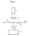
- the measuring device comprises a light source 1, preferably a low-energy laser light source, for example laser diodes with a power of 3 to 5 mW, an optical device 2 for bundling the light emitted by the light source, a detector device 3 for receiving the light and for emitting a detector signal S and an evaluation device 4 for evaluating the detector signal.
- a light source 1 preferably a low-energy laser light source, for example laser diodes with a power of 3 to 5 mW
- an optical device 2 for bundling the light emitted by the light source
- a detector device 3 for receiving the light and for emitting a detector signal S
- an evaluation device 4 for evaluating the detector signal.
- the optical device 2 bundles the light from the light source 1 in such a way that the light spot with the smallest diameter is generated in the plane of the endless forms.
- the light preferably runs perpendicular to the plane of the endless forms.
- the light does not penetrate the endless forms 5 or preferably only so slightly that when it reaches the detector device 3 it produces only a small detector signal S which can be used as a basic signal; If this basic signal fails to appear, an error in the measuring device can be easily identified.
- the endless forms 5 are moved in the direction of the arrow V E in FIG. 1, the light passes through the endless forms at the locations of the perforation column 5a, arrives at the detector device 3 and produces a characteristic detector signal S which is forwarded to the evaluation device 4.
- the size and type of the detector signal is evaluated by the evaluation device 4 to check the perforation gaps 5a and thus to determine the perforation strength.
- the detector signal S has the dependency on the perforation gaps 5a described below, which was determined with the aid of comparative tests on the basis of microscopic assessments and perforation strength measurements - with destruction of the perforation.
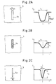
- 2A to 2C are examples to explain this dependency of the detector signal Perforation column 5a in continuous forms 5 in an enlarged view, and in S / t diagrams the corresponding detector signals S are shown, which are caused by the light passing through the perforation column.
- a perforation gap with a certain perforation gap width is formed due to the tension present during the processing of the paper web, which depends on the paper properties, the existing paper web tension and the cut / web ratio of the perforation.
- the perforation strength correlates with the width of the perforation gap, because the width indicates how far the paper is from the breaking point under the applied load.
- the width of the perforation gap indicates how much force still has to be absorbed in order to tear the paper, so that, based on the known web tension, the force which is ultimately still required to tear the perforation can be determined.
- the perforation strength can be determined on the basis of the width of the perforation gap. In this way, the paper properties are included in the measurement and assessment of the perforation strength.
- a first perforation gap 5a is shown in FIG. 2A;
- the detector signal S generated by this perforation gap is explained on the basis of the S / t diagram in FIG. 2A.
- the perforation gap 5a has a width b P and correlates with a given paper quality and a predetermined cut / web ratio of the perforation to a specific perforation strength.
- the perforation gap 5a there are no longer any paper fibers inside which connect the two long sides of the perforation gap to one another or protrude into the perforation gap, since the paper was cut cleanly when the perforation was introduced.
- the breaking strength of the paper and the cut / web ratio of the perforation determine the perforation strength with such a perforation gap.
- the detector device 3 If the perforation gap 5a acc. 2A in the area of the light path of the measuring device acc. 1, the light passes through the plane of the paper web and reaches the detector device 3. Due to the incident light, the detector device 3 generates a detector signal S, the course of which is shown in the S / t diagram in FIG. 2A.
- the detector signal S is essentially characterized by the two variables t S and h S , ie the signal duration and the signal swing.
- the maximum signal swing h max also depends on whether the light spot in the plane of the continuous forms 5 has a size that allows the entire amount of light to pass through the perforation gap 5a of width b P without a part of the light from the long sides of the perforation gap is shadowed.
- the total amount of light can only pass through the perforation gap 5a if the diameter of the light spot focused in the plane of the endless forms 5 (cf. FIG. 1) is smaller than the width b P of the perforation gap, since otherwise the The light spot as it moves across the perforation gap is always partially covered by the longitudinal edges of the perforation gap, without ever being completely within the gap. Therefore, both the light source and the optical device should preferably be designed in such a way that the smallest possible, precisely focused light spot is achieved in the plane of the endless forms.
- FIG. 2B shows a second perforation gap 5a in the continuous form 5, in which not all paper fibers have been severed in the area of the perforation gap 5a during the introduction of the perforation into the paper web.
- the width b P corresponds to the predetermined value and thus the width of the perforation gap in FIG. 2A.
- the detector signal S differs, which, according to FIG. Fig. 2B is caused, not by that of the perforation gap acc. Figure 2A.
- the signal swing h S in the case of the perforation gap is gem.
- Fig. 2B significantly lower, which is due to the hindering the passage of light effect of the remaining paper fibers in the perforation gap 5a. Poor cutting and removal of the paper fibers in the perforation gap 5a can thus be detected via the signal lift h S.
- FIG. 2C a third perforation gap 5a is shown in FIG. 2C, in which there are no longer any paper fibers inside since all the fibers have been cut through, but in which the width b P is significantly smaller than in the case of the perforation columns according to FIG. 2A or 2B.
- the smaller width b P of the third perforation gap 5a indicates that the paper has not stretched as much under the applied web tension as in FIGS Cases shown in Figs. 2A and 2B.
- the perforation strength is in accordance with a perforation.
- Fig. 2C larger.
- the signal duration t S of the detector signal which according to the perforation gap 5a. 2C is shortened accordingly in comparison with the detector signals acc. 2A or 2B.
- the signal swing h S remains large, however, since no paper fibers have remained in the interior of the perforation gap 5a.
- the detector signal S is fed to the evaluation device 4, which determines the two characteristic variables t S and h S from the course of the detector signal and determines the perforation strength or a variable corresponding thereto.
- the evaluation device 4 determines the two characteristic variables t S and h S from the course of the detector signal and determines the perforation strength or a variable corresponding thereto.
- specifications are made for the signal duration t Ssoll or the width b Psoll of the perforation gap and for the signal stroke h Ssoll , which correspond to a specific, predetermined perforation strength .
- These specifications can be determined for various types of paper using the known possibilities and methods and for the measuring device by means of suitable calibration with respect to the maximum signal swing h max in the form of simple test series and are subsequently available in the form of a table.
- the perforation strength PF is less than the specified value. Because the existing web tension stretches the perforation more than specified by the setpoint. Reducing the cut / web ratio can help here.
- the perforation strength PF of the perforation is greater than the specified value. This means that the paper presents a greater resistance to the web tension and is not stretched as far as is specified by the setpoint.
- the perforation strength can be adjusted by increasing the cut / web ratio.
- the comparisons should advantageously be carried out with the aid of the value of the width b P and the specification b Psoll if a constant movement speed V E of the endless formulars cannot be assumed.
- the evaluation device 4 is then supplied with a measurement signal corresponding to the movement speed V E of the endless forms 5, which is emitted by a suitable measurement device.
- the previously mentioned specification tables for t Ssoll and h Ssoll can be manually entered into the evaluation device 4 before the start of the production of the endless forms;
- the evaluation device 4 is advantageously equipped with an input unit, which also enables the specifications to be displayed and changed.
- the values entered in the specification table are stored in a memory unit, from where they can be called up in a simple manner without having to be entered again each time.
- the evaluation device 4 comprises a storage unit for storing the perforation strength determined in each case and an output unit via which these values or only the values which do not fall within a predetermined range can be output after completion of the production of a continuous form production volume.
- the method according to the invention for the production of continuous forms adapted to the material essentially comprises the steps of introducing the transverse perforations into the paper web, continuously measuring the perforation strength of the introduced transverse perforations and adapting the transverse perforations to be introduced such that the coefficient of variation is below a limit, preferably below 6%.
- an embodiment of the method according to the invention comprises the steps of introducing the transverse perforation into the paper web, detecting a size (t S , b P ) that corresponds to the perforation strength of the perforation, for each transverse perforation, comparing the detected size with a predetermined one Limit (t Ssoll , b psoll ) and adapting the cross perforations to be introduced by changing the cut / web ratio.
- the detection of the size corresponding to the perforation strength is carried out by the steps of irradiating a light beam, preferably a laser light beam onto the paper web such that the light beam passes through the perforation gaps of the moving paper web, detecting the light beam by means of a detector device and evaluating it Detector device emitted signal with regard to the size corresponding to the perforation strength (t S , b p ).
- the duration (t S ) of the detector signal preferably the perforation gap width (b p ), is used as the variable corresponding to the perforation strength.
- the method according to the invention comprises the step of detecting a size (h S ), which corresponds to the quality of the perforation and influences the perforation strength, for each transverse perforation and comparing the detected size with a predetermined limit value (h Ssoll ).
- Capturing the goodness of perforation Corresponding size takes place through the steps of irradiating a light beam, preferably a laser light beam, onto the paper web such that the light beam passes through the perforation column of the moving paper web, detecting the lily beam by means of a detector device and evaluating the signal emitted by the detector device with regard to to the size corresponding to the quality of the perforation (h S ).
- the signal swing (h S ) of the detector signal is used as the quantity corresponding to the quality of the perforation.
- the method according to the invention for the production of continuous forms has for the first time created a possibility of emphasizing continuous forms with material-adapted perforation and thus with almost constant perforation strength, so that compliance with the requirements for perforation strength can be guaranteed for an entire production volume. This quality has not been possible until now and represents a significant advance over the previously known methods for the production of continuous forms.
- the measurement of the two characteristic variables h S and t S can be carried out continuously and non-destructively during the production of the continuous forms without the production having to be interrupted or a random sample-like measurement being used. Rather, each individual perforation gap is detected and checked for the perforation strength achieved, so that a statement can be made about the perforation strength actually achieved during the production of the continuous forms.
- the measuring device can already influence the compliance with the requirements for the perforation strength and in some cases also ensure that the perforation device is repeatedly adjusted on the basis of the measurement results or that adjustments are made in the event of changes due to wear.
- the production of the endless forms must be interrupted or the end of a production process awaited.
- the measuring device creates a possibility of continuously regulating the perforation strength of continuous forms, since the measurement of the perforation strength according to the invention is carried out continuously and non-destructively, and also taking into account the material properties of the paper.
- the characteristic quantities t S or b P and h S can be included in a control loop for regulating the perforation strength, as will be described in detail below. In this way, a perforation is created which is adapted to the properties of the paper used.
- a control circuit of this type is shown schematically in FIG. 3, to which the characteristic variables t S and h S are supplied as actual values.
- the control loop comprises a setpoint specification 11, via which the specifications for the signal duration t Ssoll or the width b Psoll and the signal swing h Ssoll are fed to the control loop, a controller 12, via which the perforation is introduced, and the controlled system 13, on which, in addition to the controller 12, there are also disturbing influences Z, for example fluctuating paper properties.
- Behind the Controlled system 13 is the actual value transmitter 14, the measuring device described above is arranged. The measured values t S and h S are fed back to the target value 11, whereby the control loop is closed.
- the controlled system 13 is conventionally a perforation device with knife rollers for introducing the perforation.
- a counter-pressure cylinder is assigned to the knife roller parallel to the axis of the knife roller; the pressure between the two has a significant influence on the quality of the severing of the paper, ie the signal swing h S of the measurement signal. If a device for changing the pressure between the knife roller and the impression cylinder is provided as the actuator and the change is carried out on the basis of the difference between the specification h Sset and the measured value h S , the influence of paper fibers on the perforation strength can be avoided.
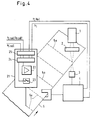
- FIG. 4 shows a laser perforation device which comprises a laser light source 21, from which a laser beam cutting the paper emerges, which preferably strikes the paper web of the continuous forms 5 perpendicularly in order to introduce the perforation cuts 5a.
- a device 22 for influencing the power output by the laser light source is provided in the laser light source 21.
- the laser light source has a device 23 for changing the cut / web ratio of the perforation. In the simplest case, this is a switching device which switches the laser beam on or off in accordance with the desired cut / web ratio.
- the laser light source 21 also includes an interface 25, via which the two measured values t S or b P and h S are supplied.
- the specifications for the signal duration t Ssoll or b Psoll and h Ssoll are also supplied via the interface 25 and arrive at the control device 24, which regulates the introduction of the perforation 5a with respect to a specific perforation strength on the basis of these values.
- the laser power that is emitted by the laser light source 21 is determined as a function of the difference between the setpoint specification h Sset and the measured value h S. Inadequate cutting of the paper fibers in the perforation gap can be avoided by increasing the laser power.
- the device 22 for influencing the laser power is controlled accordingly by the control device 24 in order to improve the severing of the paper fibers effect.
- the perforation strength is corrected in relation to the influence of paper fibers remaining in the perforation gap. An attempt is advantageously made to keep the laser power as low as possible.
- An improved severing can also be achieved if the paper web of the endless forms 5 is brought exactly into the focal plane of the laser beam or is held there. Since laser perforation devices are generally equipped with a focusing device for the laser beam, tracking of the focusing can also be provided if necessary. Both the change in the laser power and the tracking of the focusing are measures which can be carried out automatically, so that the perforation strength with respect to the characteristic size h S , that is to say with regard to the quality of the severing of the paper fibers in the perforation gap in the range of the specification h Sset, is achieved in a simple manner can be held.
- the cut / land ratio of the perforation is determined as a function of the difference between the setpoint specification t Ssoll and the measured value t S or b Psoll and b P.
- the device 23 for changing the cut / web ratio is controlled accordingly in such a way that a weakening of the load-bearing paper cross section which is too strong or too small is compensated for, which is noticeable by too large or too small distances between the edges of the detector signal.
- the perforation strength which is increased due to the width b P of the perforation gap being too small, can be increased by a suitable increase in the cut / web ratio in favor of the cut portion is recognized, adjusted to the desired value.
- endless forms can be produced, the perforation of which is adapted to the material.
- the regulation ensures that fluctuations in the paper properties are compensated for by a corresponding adaptation of the perforation formation.
- the perforation strength is therefore less scattered than would be expected due to the fluctuating paper properties.
- the regulation is based on a complete and non-destructive determination of the perforation strength and leads to a material-adapted perforation of the paper web.
- the continuous forms with material-adapted perforation are characterized by the fact that compliance with the specification and the associated requirements for the continuous forms with regard to further processing in processing systems, such as computer printers, is certain. So far there has been no review-based regulation for fulfilling the requirements placed on the endless forms, so that only far Range limits for the perforation were reliably realizable.
- the material-adapted perforated endless forms in which the coefficient of variation, ie the deviation of the perforation strength from an average value is below a limit value, preferably below 6%, offer considerable advantages with regard to their reliability and usability.
Landscapes
- Physics & Mathematics (AREA)
- Optics & Photonics (AREA)
- Engineering & Computer Science (AREA)
- Mechanical Engineering (AREA)
- Plasma & Fusion (AREA)
- Life Sciences & Earth Sciences (AREA)
- Forests & Forestry (AREA)
- Perforating, Stamping-Out Or Severing By Means Other Than Cutting (AREA)
- Dowels (AREA)
- Length Measuring Devices By Optical Means (AREA)
- Controlling Rewinding, Feeding, Winding, Or Abnormalities Of Webs (AREA)
Claims (9)
- Formulaires en continu, imprimés ou non imprimés, comportant au moins des perforations transversales, qui servent de perforations de séparation et/ou de pliage,
caractérisés en ce que les formulaires en continu comportent des perforations transversales (5a) présentant un rapport coupes/intervalles entre coupes variant de manière visée et telle, que le coefficient de variation de la résistance de perforation se situe en-dessous d'une valeur limite prédéterminée, de préférence en-dessous de 6%. - Formulaires en continu, selon la revendication 1, caractérisés en ce que le coefficient de variation de la résistance de perforation se situe en-dessous de 4%.
- Formulaires en continue, selon l'une des revendications 1 ou 2, caractérisés en ce que la largeur (bp) des fentes de perforation, qui se forment, sous une tension de bande déteérminée, dans la zone des perforations transversales (5a), ne s'écarte d'une valeur (bpcons), qui correspond à la résistance de perforation prédéterminée, que d'une quantité qui correspond à la valeur limite du coefficient de variation de la résistance de perforation.
- Formulaires en continu, selon l'une des revendications 1, 2 ou 3, caractérisés en ce que la qualité (hs) de la perforation est toujours supérieure ou égale à une valeur limite prédéterminée (hscons).
- Procédé de fabrication de formulaires en continu, imprimés ou non imprimés, comportant au moins des perforations transversales, qui servent de perforations de séparations et/ou de pliage, présentant les étapes suivantes:
réalisation de perforations transversales (5a) dans une bande de papier (5),
émission d'un rayon lumineux, de préférence un rayon lumineux laser, sur la bande de papier (5) de manière telle, que le rayon lumineux traverse la fente de perforation de la bande de papier (5) déplacée, en fonction de mouvement de déplacement,
détection du rayon lumineux au moyen d'un dispositif de détecteur (3),
traitement d'un signal délivré par le dispositif de détecteur (3), quant à la durée (tS) du signal du détecteur, et
adaption du réglage déteminant le rapport coupes/intervalles entre coupes, du dispositif de perforation réalisant les perforations transversales, en fonction du résultat de traitement du signal, de façon à ce que les perforations transversales présentent un rapport coupes/intervalles entre coupes variant de manière visée et telle, que le coefficient de variation de la résistance de perforation se situe en-dessous d'une valeur limite prédéterminée, de préférence en-dessous de 6%. - Procédé selon la revendication 5, caractérisé par les étapes suivantes:
relevé de la grandeur (ts, bp) correspondant à la résistance de perforation, pour chacune des perforations transversales (5a),
comparaison de chaque grandeur relevée, à une valeur limite prédéterminée (tscons, bpcons). - Procédé selon la revendication 6, caractérisé par les étapes suivantes:
relevé de la vitesse (vE) de la bande de papier (5) déplacée,
traitement d'un signal délivré par le dispositif de détecteur (3), quant à la largeur de la fente de perforation (bp). - Procédé selon la revendications 5 à 7, caractérisé par les étapes:
relevé d'une grandeur (hs) correspondant à la qualité de la perforation et influençant la résistance de perforation, pour chacune des perforations transversales (5a), et
comparaison de chaque grandeur relevée à une valeur limite (hscons) prédéterminée. - Procédé selon la revendication 8, caractérisé en ce que le relevé de la grandeur correspondant à la qualité de la perforation (5a) est effectué par les étapes suivantes:
émission d'un rayon lumineux, de préférence un rayon lumineux laser sur la bande de papier (5), de manière telle, que le rayon lumineux traverse la fente de perforation de la bande de papier (5) déplacée, en fonction du mouvement de déplacement,
détection du rayon lumineux au moyen d'un dispositif de détecteur (3), et
traitement d'un signal délivré par le dispositif de détecteur (3), quant à l'amplitude de signal (hs) du signal de détecteur.
Applications Claiming Priority (2)
| Application Number | Priority Date | Filing Date | Title |
|---|---|---|---|
| DE4133348A DE4133348C2 (de) | 1991-10-08 | 1991-10-08 | Materialangepaßte perforierte Endlosblätter einer Materialbahn, insbesondere einer Papierbahn sowie Vorrichtung und Verfahren zu deren Herstellung |
| DE4133348 | 1991-10-08 |
Publications (2)
| Publication Number | Publication Date |
|---|---|
| EP0536686A1 EP0536686A1 (fr) | 1993-04-14 |
| EP0536686B1 true EP0536686B1 (fr) | 1996-05-22 |
Family
ID=6442283
Family Applications (1)
| Application Number | Title | Priority Date | Filing Date |
|---|---|---|---|
| EP92117019A Expired - Lifetime EP0536686B1 (fr) | 1991-10-08 | 1992-10-06 | Bande de formulaires ayant une perforation adaptée à la qualité du matériel, appareil et méthode pour sa fabrication |
Country Status (4)
| Country | Link |
|---|---|
| EP (1) | EP0536686B1 (fr) |
| AT (1) | ATE138307T1 (fr) |
| DE (2) | DE4133348C2 (fr) |
| ES (1) | ES2090446T3 (fr) |
Families Citing this family (1)
| Publication number | Priority date | Publication date | Assignee | Title |
|---|---|---|---|---|
| AT515408B1 (de) * | 2014-04-03 | 2015-09-15 | Tannpapier Gmbh | Diffusionsoptimiertes Mundstückbelagpapier |
Family Cites Families (3)
| Publication number | Priority date | Publication date | Assignee | Title |
|---|---|---|---|---|
| DE3318214A1 (de) * | 1982-06-01 | 1983-12-01 | Hauni-Werke Körber & Co KG, 2050 Hamburg | Perforiervorrichtung |
| DE3728660A1 (de) * | 1987-08-27 | 1989-03-09 | Baasel Carl Lasertech | Geraet zur substratbehandlung, insbesondere zum perforieren von papier |
| US5028040A (en) * | 1990-01-08 | 1991-07-02 | Moore Business Forms, Inc. | Apparatus and methods for verifying registration of form parts and forms therefor |
-
1991
- 1991-10-08 DE DE4133348A patent/DE4133348C2/de not_active Expired - Fee Related
-
1992
- 1992-10-06 ES ES92117019T patent/ES2090446T3/es not_active Expired - Lifetime
- 1992-10-06 AT AT92117019T patent/ATE138307T1/de not_active IP Right Cessation
- 1992-10-06 DE DE59206354T patent/DE59206354D1/de not_active Expired - Fee Related
- 1992-10-06 EP EP92117019A patent/EP0536686B1/fr not_active Expired - Lifetime
Also Published As
| Publication number | Publication date |
|---|---|
| ES2090446T3 (es) | 1996-10-16 |
| EP0536686A1 (fr) | 1993-04-14 |
| DE59206354D1 (de) | 1996-06-27 |
| DE4133348A1 (de) | 1993-04-15 |
| DE4133348C2 (de) | 1996-02-29 |
| ATE138307T1 (de) | 1996-06-15 |
Similar Documents
| Publication | Publication Date | Title |
|---|---|---|
| DE19882374B4 (de) | Verfahren zur Bestimmung der Qualität der Formierung einer Bobine oder Rolle einer Papier - oder Kartonbahn und zur Steuerung der Bobinen - oder Rollenformierung und - wicklung | |
| EP3679102B1 (fr) | Procédé et dispositif pour la fabrication d'un ruban adhésif | |
| EP0894895B1 (fr) | Procédé et dispositif de détection et de correction des changements du profil transversal d'orientation des fibres | |
| DE68918468T2 (de) | Vorrichtung zur Überwachung der Herstellung von Papierrollen. | |
| EP2571679B1 (fr) | Dispositif et procédé pour produire des sections de tube pour la fabrication de sacs | |
| DE19910569A1 (de) | Verfahren und Wickelmaschine zum Aufwickeln einer Materialbahn | |
| EP0536686B1 (fr) | Bande de formulaires ayant une perforation adaptée à la qualité du matériel, appareil et méthode pour sa fabrication | |
| DE4133312C2 (de) | Vorrichtung zur Herstellung von materialangepaßt perforierten Endlosformularen | |
| EP0381112B1 (fr) | Procédé et dispositif pour travailler des bandes en registre, spécialement pour des fils de sécurités | |
| EP0536695A1 (fr) | Formulaires continus continuellement contrôlés de perforations, procédé et appareil pour leur fabrication | |
| EP0985763A2 (fr) | Machine pour la fabrication d'une bande de matériau | |
| WO2007144185A1 (fr) | Procédé et dispositif de traitement d'une bande de matière défilante | |
| EP1867593A1 (fr) | Méthode et dispositif pour le traitement d'une bande en mouvement | |
| EP1614801B1 (fr) | Machine pour fabriquer une bande de matière fibreuse | |
| EP1179632B1 (fr) | Procédé et dispositif pour le transfert d'une bande flexible | |
| DE3529098A1 (de) | Vorrichtung zum herstellen von aus miteinander verklebten textilstuecken bestehenden textileinheiten | |
| EP3954527A1 (fr) | Procédé de fabrication d'un film en matière plastique | |
| DE20220537U1 (de) | Vorrichtung zum Aufwickeln einer Materialbahn | |
| DE4243721A1 (en) | Electro-erosive micro perforation of highly porous filter paper line - carried out so that paper lines are forced to undergo additional electro-erosive micro perforations to increase air and/or water permeability to reach desired value | |
| EP0534080B1 (fr) | Bande de formulaires controlée continuellement, dispositif et méthode pour sa fabrication | |
| DE102007056499B4 (de) | Verfahren und Vorrichtung zur Abrisserkennung an papierherstellenden und weiterverarbeitenden Maschinen | |
| DE202025101005U1 (de) | Schneideinrichtung zum Schneiden eines bandförmigen Materials, insbesondere eines klebrigen Cordbands | |
| LU87956A1 (de) | Regelsystem zur positionierung vorgegebener markierungen an folienbahnen bei deren verwendung in automatischen herstellungsprozessen | |
| DE3318214A1 (de) | Perforiervorrichtung | |
| DE2914730A1 (de) | Verfahren zur messung der laufeigenschaften von papierwerkstoff in einer verarbeitungsmaschine |
Legal Events
| Date | Code | Title | Description |
|---|---|---|---|
| PUAI | Public reference made under article 153(3) epc to a published international application that has entered the european phase |
Free format text: ORIGINAL CODE: 0009012 |
|
| AK | Designated contracting states |
Kind code of ref document: A1 Designated state(s): AT BE CH DE DK ES FR GB IT LI NL SE |
|
| 17P | Request for examination filed |
Effective date: 19930510 |
|
| 17Q | First examination report despatched |
Effective date: 19941209 |
|
| GRAH | Despatch of communication of intention to grant a patent |
Free format text: ORIGINAL CODE: EPIDOS IGRA |
|
| GRAA | (expected) grant |
Free format text: ORIGINAL CODE: 0009210 |
|
| AK | Designated contracting states |
Kind code of ref document: B1 Designated state(s): AT BE CH DE DK ES FR GB IT LI NL SE |
|
| PG25 | Lapsed in a contracting state [announced via postgrant information from national office to epo] |
Ref country code: DK Effective date: 19960522 |
|
| REF | Corresponds to: |
Ref document number: 138307 Country of ref document: AT Date of ref document: 19960615 Kind code of ref document: T |
|
| REG | Reference to a national code |
Ref country code: CH Ref legal event code: NV Representative=s name: BUECHEL & PARTNER AG PATENTBUERO |
|
| ET | Fr: translation filed | ||
| REF | Corresponds to: |
Ref document number: 59206354 Country of ref document: DE Date of ref document: 19960627 |
|
| ITF | It: translation for a ep patent filed | ||
| GBT | Gb: translation of ep patent filed (gb section 77(6)(a)/1977) |
Effective date: 19960625 |
|
| PG25 | Lapsed in a contracting state [announced via postgrant information from national office to epo] |
Ref country code: SE Effective date: 19960822 |
|
| PG25 | Lapsed in a contracting state [announced via postgrant information from national office to epo] |
Ref country code: AT Effective date: 19961006 |
|
| PG25 | Lapsed in a contracting state [announced via postgrant information from national office to epo] |
Ref country code: ES Free format text: LAPSE BECAUSE OF NON-PAYMENT OF DUE FEES Effective date: 19961007 |
|
| REG | Reference to a national code |
Ref country code: ES Ref legal event code: FG2A Ref document number: 2090446 Country of ref document: ES Kind code of ref document: T3 |
|
| PGFP | Annual fee paid to national office [announced via postgrant information from national office to epo] |
Ref country code: FR Payment date: 19961029 Year of fee payment: 5 |
|
| PG25 | Lapsed in a contracting state [announced via postgrant information from national office to epo] |
Ref country code: LI Effective date: 19961031 Ref country code: CH Effective date: 19961031 Ref country code: BE Effective date: 19961031 |
|
| REG | Reference to a national code |
Ref country code: ES Ref legal event code: FG2A Ref document number: 2090446 Country of ref document: ES Kind code of ref document: T3 |
|
| PGFP | Annual fee paid to national office [announced via postgrant information from national office to epo] |
Ref country code: DE Payment date: 19961127 Year of fee payment: 5 |
|
| PLBE | No opposition filed within time limit |
Free format text: ORIGINAL CODE: 0009261 |
|
| BERE | Be: lapsed |
Owner name: ZWECKFORM BURO-PRODUKTE G.M.B.H. Effective date: 19961031 |
|
| PG25 | Lapsed in a contracting state [announced via postgrant information from national office to epo] |
Ref country code: NL Effective date: 19970501 |
|
| 26N | No opposition filed | ||
| REG | Reference to a national code |
Ref country code: CH Ref legal event code: PL |
|
| NLV4 | Nl: lapsed or anulled due to non-payment of the annual fee |
Effective date: 19970501 |
|
| PG25 | Lapsed in a contracting state [announced via postgrant information from national office to epo] |
Ref country code: FR Free format text: THE PATENT HAS BEEN ANNULLED BY A DECISION OF A NATIONAL AUTHORITY Effective date: 19971031 |
|
| PGFP | Annual fee paid to national office [announced via postgrant information from national office to epo] |
Ref country code: GB Payment date: 19980326 Year of fee payment: 6 |
|
| PG25 | Lapsed in a contracting state [announced via postgrant information from national office to epo] |
Ref country code: DE Free format text: LAPSE BECAUSE OF NON-PAYMENT OF DUE FEES Effective date: 19980701 |
|
| REG | Reference to a national code |
Ref country code: FR Ref legal event code: ST |
|
| PG25 | Lapsed in a contracting state [announced via postgrant information from national office to epo] |
Ref country code: GB Free format text: LAPSE BECAUSE OF NON-PAYMENT OF DUE FEES Effective date: 19981006 |
|
| GBPC | Gb: european patent ceased through non-payment of renewal fee |
Effective date: 19981006 |
|
| REG | Reference to a national code |
Ref country code: ES Ref legal event code: FD2A Effective date: 19971112 |
|
| PG25 | Lapsed in a contracting state [announced via postgrant information from national office to epo] |
Ref country code: IT Free format text: LAPSE BECAUSE OF NON-PAYMENT OF DUE FEES;WARNING: LAPSES OF ITALIAN PATENTS WITH EFFECTIVE DATE BEFORE 2007 MAY HAVE OCCURRED AT ANY TIME BEFORE 2007. THE CORRECT EFFECTIVE DATE MAY BE DIFFERENT FROM THE ONE RECORDED. Effective date: 20051006 |