EP0536854A2 - Ensemble porte-filière - Google Patents
Ensemble porte-filière Download PDFInfo
- Publication number
- EP0536854A2 EP0536854A2 EP92203610A EP92203610A EP0536854A2 EP 0536854 A2 EP0536854 A2 EP 0536854A2 EP 92203610 A EP92203610 A EP 92203610A EP 92203610 A EP92203610 A EP 92203610A EP 0536854 A2 EP0536854 A2 EP 0536854A2
- Authority
- EP
- European Patent Office
- Prior art keywords
- bore
- groove
- retaining ring
- ring
- die head
- Prior art date
- Legal status (The legal status is an assumption and is not a legal conclusion. Google has not performed a legal analysis and makes no representation as to the accuracy of the status listed.)
- Withdrawn
Links
Images


Classifications
-
- B—PERFORMING OPERATIONS; TRANSPORTING
- B23—MACHINE TOOLS; METAL-WORKING NOT OTHERWISE PROVIDED FOR
- B23G—THREAD CUTTING; WORKING OF SCREWS, BOLT HEADS, OR NUTS, IN CONJUNCTION THEREWITH
- B23G1/00—Thread cutting; Automatic machines specially designed therefor
- B23G1/26—Manually-operated thread-cutting devices
-
- Y—GENERAL TAGGING OF NEW TECHNOLOGICAL DEVELOPMENTS; GENERAL TAGGING OF CROSS-SECTIONAL TECHNOLOGIES SPANNING OVER SEVERAL SECTIONS OF THE IPC; TECHNICAL SUBJECTS COVERED BY FORMER USPC CROSS-REFERENCE ART COLLECTIONS [XRACs] AND DIGESTS
- Y10—TECHNICAL SUBJECTS COVERED BY FORMER USPC
- Y10T—TECHNICAL SUBJECTS COVERED BY FORMER US CLASSIFICATION
- Y10T403/00—Joints and connections
- Y10T403/60—Biased catch or latch
-
- Y—GENERAL TAGGING OF NEW TECHNOLOGICAL DEVELOPMENTS; GENERAL TAGGING OF CROSS-SECTIONAL TECHNOLOGIES SPANNING OVER SEVERAL SECTIONS OF THE IPC; TECHNICAL SUBJECTS COVERED BY FORMER USPC CROSS-REFERENCE ART COLLECTIONS [XRACs] AND DIGESTS
- Y10—TECHNICAL SUBJECTS COVERED BY FORMER USPC
- Y10T—TECHNICAL SUBJECTS COVERED BY FORMER US CLASSIFICATION
- Y10T403/00—Joints and connections
- Y10T403/70—Interfitted members
- Y10T403/7075—Interfitted members including discrete retainer
- Y10T403/7077—Interfitted members including discrete retainer for telescoping members
-
- Y—GENERAL TAGGING OF NEW TECHNOLOGICAL DEVELOPMENTS; GENERAL TAGGING OF CROSS-SECTIONAL TECHNOLOGIES SPANNING OVER SEVERAL SECTIONS OF THE IPC; TECHNICAL SUBJECTS COVERED BY FORMER USPC CROSS-REFERENCE ART COLLECTIONS [XRACs] AND DIGESTS
- Y10—TECHNICAL SUBJECTS COVERED BY FORMER USPC
- Y10T—TECHNICAL SUBJECTS COVERED BY FORMER US CLASSIFICATION
- Y10T408/00—Cutting by use of rotating axially moving tool
- Y10T408/63—Tool or tool-support with torque-applying ratchet
- Y10T408/643—Reversible ratchet
-
- Y—GENERAL TAGGING OF NEW TECHNOLOGICAL DEVELOPMENTS; GENERAL TAGGING OF CROSS-SECTIONAL TECHNOLOGIES SPANNING OVER SEVERAL SECTIONS OF THE IPC; TECHNICAL SUBJECTS COVERED BY FORMER USPC CROSS-REFERENCE ART COLLECTIONS [XRACs] AND DIGESTS
- Y10—TECHNICAL SUBJECTS COVERED BY FORMER USPC
- Y10T—TECHNICAL SUBJECTS COVERED BY FORMER US CLASSIFICATION
- Y10T408/00—Cutting by use of rotating axially moving tool
- Y10T408/94—Tool-support
- Y10T408/95—Tool-support with tool-retaining means
Definitions
- a diestock assembly comprising head means having a first bore for receiving a driving ring member, said first bore having an axis, means securing said ring member in said first bore, said ring member having a second bore coaxial with said first bore for detachably receiving a cutting die head, said second bore coaxial with said first bore for detachably receiving a cutting die head, said second bore having inner wall means, a circumferentially extending groove in said inner wall means, radially expandable retaining ring means in said groove, and said cutting die head including means interengaging with said retaining ring means to detachably secure said cutting die head in said second bore, characterized by said inner wall means providing at least two diametrically opposed corners facing inwardly of said second bore, means supporting said retaining ring means in said groove against rotation relative to said axis and for expansion radially outwardly thereof, said retaining ring means including portions, spanning said at least two corners radially inwardly
- the retaining ring and groove arrangement includes a split retaining spring ring which is non-circular in its circumferential contour and which interengages with the groove in which it is carried such that the retaining ring is restrained against lateral and circumferential displacement relative to the ratchet ring or adaptor ring bore.
- the interengaging support between the retaining ring groove and the retaining ring provides for the latter to be self-centering relative to the bore and assures a positioning of the ends of the restraining ring which precludes exposure thereof radially inwardly of the bore and thus avoids potential interference with the die head during introduction thereof into the ratchet ring or adaptor ring bore.
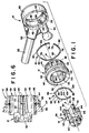
- FIG. 1 illustrate a diestock assembly comprising a head assembly 10, a driving member 12 and a thread cutting die head 14.
- driving member 12 and head assembly 10 are detachably interengaged by means of a resilient, split retaining spring member 16
- die head 14 and driving member 12 are detachably interconnected by means of a resilient, split retaining spring member 18.
- head assembly 10 includes a ratchet housing 20 having a circular bore 22 therethrough providing the ratchet housing with an axis A, with an inner wall including axially adjacent circular wall portions 24 and 26, and with a radially inwardly extending flange 28 at one end of the housing.
- the ratchet housing includes a radially extending portion 30 adapted to receive a handle 32 suitably interengaged therewith such as by threading and which provides for the head assembly to be manually rotated about axis A.
- each pair of surfaces 64 are tapered as indicated by numeral 68, and each pair of surfaces 64 is further provided with a generally V-shaped notch 70 extending circumferentially thereacross.
- Lobes 76 and 80 are diametrically opposite one another and equidistant from lobe 78, and lobe 78 is diametrically opposite a point midway between ends 72 and 74 of the retaining ring.
- Recess 42 in ratchet housing 20 has a bottom wall 42a, and retaining ring 16 has a dimension between lobes 76 and 80 and between lobe 78 and ring ends 72 and 74 which provides for the lobes and ring ends to engage bottom 42a of recess 42 when the ring is in place in the recess.
- ring 16 in its unmounted disposition is of a diameter larger than that of bottom 42a of recess 42, whereby the ring is supported in recess 42 in compression so as to positively force the lobes and ring ends against the bottom of the recess.
- a suitable retaining ring member can be constructed from 2 mm (0.080) diameter oil tempered spring steel ASTM-A229.
- the recess has a depth of about 2.5 mm (0.1 inch)
- the lobes have a radius of curvature of about 25.4 mm (1.0 inch)
- the arcuate contour of legs 82 provides for the exposed portions thereof to have a maximum extension of about 1.3 mm (0.05 inch) into bore 22.
Landscapes
- Engineering & Computer Science (AREA)
- Mechanical Engineering (AREA)
- Snaps, Bayonet Connections, Set Pins, And Snap Rings (AREA)
- Forging (AREA)
- Toys (AREA)
- Mechanical Pencils And Projecting And Retracting Systems Therefor, And Multi-System Writing Instruments (AREA)
Applications Claiming Priority (2)
| Application Number | Priority Date | Filing Date | Title |
|---|---|---|---|
| US46099 | 1987-05-05 | ||
| US07/046,099 US4752163A (en) | 1987-05-05 | 1987-05-05 | Thread cutting diestock assembly |
Related Parent Applications (1)
| Application Number | Title | Priority Date | Filing Date |
|---|---|---|---|
| EP88630087.0 Division | 1988-05-03 |
Publications (2)
| Publication Number | Publication Date |
|---|---|
| EP0536854A2 true EP0536854A2 (fr) | 1993-04-14 |
| EP0536854A3 EP0536854A3 (en) | 1993-06-16 |
Family
ID=21941608
Family Applications (2)
| Application Number | Title | Priority Date | Filing Date |
|---|---|---|---|
| EP19920203610 Withdrawn EP0536854A3 (en) | 1987-05-05 | 1988-05-03 | Thread cutting diestock assembly |
| EP88630087A Expired - Lifetime EP0291439B1 (fr) | 1987-05-05 | 1988-05-03 | Ensemble porte-filière |
Family Applications After (1)
| Application Number | Title | Priority Date | Filing Date |
|---|---|---|---|
| EP88630087A Expired - Lifetime EP0291439B1 (fr) | 1987-05-05 | 1988-05-03 | Ensemble porte-filière |
Country Status (8)
| Country | Link |
|---|---|
| US (1) | US4752163A (fr) |
| EP (2) | EP0536854A3 (fr) |
| JP (1) | JPS63295119A (fr) |
| AU (2) | AU603663B2 (fr) |
| BR (1) | BR8802172A (fr) |
| CA (1) | CA1267508A (fr) |
| DE (1) | DE3882084T2 (fr) |
| ES (1) | ES2041824T3 (fr) |
Families Citing this family (17)
| Publication number | Priority date | Publication date | Assignee | Title |
|---|---|---|---|---|
| US5232245A (en) * | 1991-11-19 | 1993-08-03 | Trw Vehicle Safety Systems Inc. | Spring clip for passive seat belt system |
| ES2060484B1 (es) * | 1991-11-22 | 1997-02-16 | Super Ego Tools | Sistema para sujetar cabezas de roscar en roscadoras. |
| US20070031202A1 (en) * | 2005-08-05 | 2007-02-08 | Mu Hsien-Chung T | Tap and die ratcheting wrench assembly |
| US20080210062A1 (en) * | 2007-03-01 | 2008-09-04 | Emerson Electric Co. | Ratcheting manual threader drive device |
| US7793569B2 (en) * | 2007-03-14 | 2010-09-14 | Irwin Industrial Tool Company | Wrench |
| US8434390B2 (en) * | 2007-05-01 | 2013-05-07 | Irwin Industrial Tool Company | Flexible threading system |
| US8375831B2 (en) | 2007-10-30 | 2013-02-19 | Easco Hand Tools, Inc. | Tool locking mechanism |
| US20090308208A1 (en) * | 2008-06-12 | 2009-12-17 | Glen Russel Stevick | Anti-Slip Pipe Threading Wrench |
| US20110116882A1 (en) * | 2009-11-16 | 2011-05-19 | Mark Chen | Inner and outer thread tapping tool |
| CN103894684B (zh) * | 2014-04-11 | 2016-02-24 | 贵州红林机械有限公司 | 螺纹环规的螺纹内孔数控二次车削方法及其专用夹具 |
| US10087995B2 (en) | 2014-06-06 | 2018-10-02 | Saint-Gobain Performance Plastics Rencol Limited | Tolerance ring |
| US9802585B2 (en) * | 2014-11-25 | 2017-10-31 | Deere & Company | Linkage assembly |
| WO2019177776A1 (fr) * | 2018-03-16 | 2019-09-19 | Milwaukee Electric Tool Corporation | Dispositif de filetage de tuyau |
| US12109623B2 (en) | 2019-11-01 | 2024-10-08 | Milwaukee Electric Tool Corporation | Portable pipe threader |
| US12138702B2 (en) | 2019-11-01 | 2024-11-12 | Milwaukee Electric Tool Corporation | Portable pipe threader |
| US12390870B2 (en) | 2021-03-31 | 2025-08-19 | Milwaukee Electric Tool Corporation | Lubrication system for portable pipe threader |
| ES2948270A1 (es) * | 2022-02-15 | 2023-09-07 | Pardo Galvez Jose Luis | Proceso de conformación que proporciona el fibrado estructural complementario en la obtención de materiales o elementos de construcción en general |
Citations (2)
| Publication number | Priority date | Publication date | Assignee | Title |
|---|---|---|---|---|
| US2004639A (en) | 1933-04-11 | 1935-06-11 | Ridge Tool Co | Diestock |
| US4213723A (en) | 1977-01-07 | 1980-07-22 | Rems-Werk Christian Foll Und Sohne Gmbh & Co. | Thread cutting die stock |
Family Cites Families (13)
| Publication number | Priority date | Publication date | Assignee | Title |
|---|---|---|---|---|
| US858892A (en) * | 1906-11-01 | 1907-07-02 | Augustus Leicester Moss | Wrench. |
| US1450211A (en) * | 1919-10-15 | 1923-04-03 | Arlie E Kopp | Ratchet plate and die |
| US1395888A (en) * | 1920-03-15 | 1921-11-01 | Ayotte Joseph Rene | Hand-tool |
| US2255009A (en) * | 1939-10-20 | 1941-09-02 | Ridge Tool Co | Ratchet diestock |
| GB610640A (en) * | 1946-04-12 | 1948-10-19 | Tom Carrington | Improvements in or relating to screw thread cutting or like die stocks or holders |
| DE1075898B (de) * | 1956-09-14 | 1960-02-18 | Agfa Ag | Vorrichtung zur loesbaren Verbindung von Geraeteteilen |
| US3079188A (en) * | 1961-02-23 | 1963-02-26 | Bausch & Lomb | Demountable coupling |
| US3097871A (en) * | 1961-07-05 | 1963-07-16 | Mcnally Bros Machine & Gear Co | Coupling device |
| US3187610A (en) * | 1963-10-15 | 1965-06-08 | Charles O Russman | Telescopic multiple wrench |
| FR1384071A (fr) * | 1963-11-15 | 1965-01-04 | A Decoret Ets | Perfectionnements aux dispositifs de filetage |
| US3347293A (en) * | 1965-12-23 | 1967-10-17 | Magna Driver Corp | Removable bit construction for screwdrivers and the like |
| GB1546152A (en) * | 1976-10-16 | 1979-05-16 | Cross Mfg Co | Couplings |
| US4575048A (en) * | 1984-06-15 | 1986-03-11 | Jamesbury Corporation | Insert retainer for a wafer style butterfly valve |
-
1987
- 1987-05-05 US US07/046,099 patent/US4752163A/en not_active Expired - Fee Related
-
1988
- 1988-05-02 JP JP63109831A patent/JPS63295119A/ja active Pending
- 1988-05-03 EP EP19920203610 patent/EP0536854A3/en not_active Withdrawn
- 1988-05-03 AU AU15801/88A patent/AU603663B2/en not_active Ceased
- 1988-05-03 EP EP88630087A patent/EP0291439B1/fr not_active Expired - Lifetime
- 1988-05-03 DE DE88630087T patent/DE3882084T2/de not_active Expired - Fee Related
- 1988-05-03 ES ES198888630087T patent/ES2041824T3/es not_active Expired - Lifetime
- 1988-05-04 BR BR8802172A patent/BR8802172A/pt not_active IP Right Cessation
- 1988-05-04 CA CA000565914A patent/CA1267508A/fr not_active Expired
-
1990
- 1990-08-06 AU AU60243/90A patent/AU6024390A/en not_active Abandoned
Patent Citations (2)
| Publication number | Priority date | Publication date | Assignee | Title |
|---|---|---|---|---|
| US2004639A (en) | 1933-04-11 | 1935-06-11 | Ridge Tool Co | Diestock |
| US4213723A (en) | 1977-01-07 | 1980-07-22 | Rems-Werk Christian Foll Und Sohne Gmbh & Co. | Thread cutting die stock |
Also Published As
| Publication number | Publication date |
|---|---|
| EP0536854A3 (en) | 1993-06-16 |
| AU603663B2 (en) | 1990-11-22 |
| ES2041824T3 (es) | 1993-12-01 |
| JPS63295119A (ja) | 1988-12-01 |
| AU6024390A (en) | 1990-11-15 |
| CA1267508A (fr) | 1990-04-10 |
| AU1580188A (en) | 1988-11-10 |
| EP0291439B1 (fr) | 1993-06-30 |
| DE3882084T2 (de) | 1993-10-21 |
| BR8802172A (pt) | 1988-12-06 |
| EP0291439A2 (fr) | 1988-11-17 |
| DE3882084D1 (de) | 1993-08-05 |
| EP0291439A3 (en) | 1990-05-16 |
| US4752163A (en) | 1988-06-21 |
Similar Documents
| Publication | Publication Date | Title |
|---|---|---|
| EP0536854A2 (fr) | Ensemble porte-filière | |
| US4308768A (en) | Ratchet lever | |
| US4810144A (en) | Tube connector | |
| JPS5920901Y2 (ja) | 切削工具 | |
| US4854764A (en) | Coupling device between two elements | |
| US5352071A (en) | Hole saw arbor with retaining mechanism | |
| GB1583518A (en) | Locking member | |
| EP0219268A2 (fr) | Tête pour un dispositif d'élargement de tubes | |
| GB2178473A (en) | Fastener eg cable clamp | |
| US4535616A (en) | Flaring tool | |
| GB2067945A (en) | Weld backing ring | |
| US3777358A (en) | Method of assemblying a retained fastener assembly | |
| US5794949A (en) | Collet | |
| US4111442A (en) | Floating tool holder | |
| EP0108493B1 (fr) | Mandrin extensible pour tour à bois | |
| JP2660034B2 (ja) | 自在継手 | |
| US4746131A (en) | Apparatus for internal chucking of soft three-jaw chucks on lathes | |
| US3758125A (en) | Tool holding device | |
| EP0684884B1 (fr) | Dispositif de fixation pour fraiseuses et machines similaires et adaptable a des dimensions de support differentes | |
| US4676126A (en) | Adjustable wrench head for spanner nuts | |
| US5190300A (en) | Top jaw and wedge connector | |
| US2242954A (en) | Diestock | |
| EP0113532A1 (fr) | Raccord | |
| US4919574A (en) | Tool holder retention system | |
| EP0138336A1 (fr) | Outil de tournage |
Legal Events
| Date | Code | Title | Description |
|---|---|---|---|
| PUAI | Public reference made under article 153(3) epc to a published international application that has entered the european phase |
Free format text: ORIGINAL CODE: 0009012 |
|
| AC | Divisional application: reference to earlier application |
Ref document number: 291439 Country of ref document: EP |
|
| AK | Designated contracting states |
Kind code of ref document: A2 Designated state(s): BE DE ES FR GB IT NL SE |
|
| PUAL | Search report despatched |
Free format text: ORIGINAL CODE: 0009013 |
|
| AK | Designated contracting states |
Kind code of ref document: A3 Designated state(s): BE DE ES FR GB IT NL SE |
|
| 17P | Request for examination filed |
Effective date: 19931030 |
|
| 17Q | First examination report despatched |
Effective date: 19941119 |
|
| 18D | Application deemed to be withdrawn |
Effective date: 19950321 |