EP0536899B1 - Système de formation de la foule - Google Patents
Système de formation de la foule Download PDFInfo
- Publication number
- EP0536899B1 EP0536899B1 EP92308191A EP92308191A EP0536899B1 EP 0536899 B1 EP0536899 B1 EP 0536899B1 EP 92308191 A EP92308191 A EP 92308191A EP 92308191 A EP92308191 A EP 92308191A EP 0536899 B1 EP0536899 B1 EP 0536899B1
- Authority
- EP
- European Patent Office
- Prior art keywords
- fabric
- interweaving
- heddles
- threads
- piece
- Prior art date
- Legal status (The legal status is an assumption and is not a legal conclusion. Google has not performed a legal analysis and makes no representation as to the accuracy of the status listed.)
- Expired - Lifetime
Links
Images



Classifications
-
- D—TEXTILES; PAPER
- D03—WEAVING
- D03J—AUXILIARY WEAVING APPARATUS; WEAVERS' TOOLS; SHUTTLES
- D03J1/00—Auxiliary apparatus combined with or associated with looms
- D03J1/008—Cooling systems
-
- D—TEXTILES; PAPER
- D03—WEAVING
- D03C—SHEDDING MECHANISMS; PATTERN CARDS OR CHAINS; PUNCHING OF CARDS; DESIGNING PATTERNS
- D03C3/00—Jacquards
- D03C3/22—Fluid-operated jacquards
Definitions
- the present invention relates to a system for forming the shed in a seam weaving portion for joining the ends of a fabric and to a method of forming a woven seam using the system.
- the ends of a fabric are joined together to form an endless fabric or the peripheral edge of a fabric is joined to that of another fabric to form a larger piece of fabric.
- the ends of the fabric or the peripheral edges are overlapped with each other and then sewn together or bonded together.
- fabrics for use in the manufacture of nonwoven fabrics must have a uniform structure in view of touch, laminatability and uniformity.
- the above-mentioned conventional method can not be used for fabrics which are for covering the sludge in a pressure dewatering process. This is because leakage of the sludge occurs due to the presence of a nonuniform filtering area in adjoining ends of a fabric to face each other, removing transversal or weft threads in one of the joining ends over a seam width to leave longitudinal or warp threads alone, introducing the warp threads into a fabric structure of the other joining end, and cutting and removing parallel warp threads of the other joining end.
- this method is not practically available unless the fabric is a coarse mesh.
- the Jacquard device generally used in seaming machines requires longitudinal needles, transversal needles, knives, pattern cards, cylinders for receiving the pattern cards and inevitably has a large size. It is therefore inappropriate to use the Jacquard device in forming a woven seam which is narrow.
- the Jacquard device has heddles each of which is supported at both upper and lower end thereof and moved for the shed formation. With this structure, it is impossible to separately pick up an individual one of the heddles.
- a large number of the heddles are arranged in a seam weaving portion which is narrow, it is difficult to thread the heddles surrounded by a mass of heddle supporting members standing together closely. If a thread is snapped during the seam weaving operation, it is extremely difficult to find the particular heddle in question and to thread the particular heddle for recovery.
- the Jacquard device encounters difficulty in treating multi-layer fabrics, such as double-layer fabrics and triple-layer fabrics, which have recently been put into use.
- the term "shed” means the path through and perpendicular to the warp in a loom.
- the shed is formed by raising some warp threads by means of their harness while others are left down.
- the shuttle press through the shed to insert the filling.
- the term "shedding” means the operation of forming a shed in the weaving process.
- the heddle is a cord, round steel wire, or thin flat steel strip, or equivalent with loop or eye near the center through which one or more warp threads pass on the loom so that their movement may be controlled in weaving.
- the heddles conventionally are held at both ends by the harness frame. They control the weave pattern and shed as the harnesses are raised and lowered during weaving.
- a shedding system in a seaming machine comprising a plurality of heddles, characterized in that, each heddle is supported at only one end, and has an eye at the other end, in that each heddle is individually coupled to a piston rod of a plurality of pneumatic cylinders, and in that it further comprises a plurality of electromagnetic valves individually connected to said, pneumatic cylinder, and a control unit for producing a signal to operate said electromagnetic valves, said heddles being moved vertically upwardly and downwardly by stroke movement of said pneumatic cylinders to thereby form a shed in an array of threads, said threads individually passing through eyes of said heddles.
- the shedding system of the invention also includes a cooling fan for cooling the electromagnetic valves and a control unit having a memory for memorizing a fabric structure.
- Each of the heddles used in the present invention is a solid body formed of metal or plastics.
- the heddles can be molded into a shape having an arcuate section or an undulating section. Any suitable metal or plastic having the properties necessary to perform this function can be used to make the heddle.
- Another object of the invention is to provide a method of joining the ends of a fabric woven seam to form an endless fabric using the shedding system of the present invention.
- a method of joining the ends of a fabric by a woven seam to form an endless fabric comprising the steps of: (a) preparing an interweaving piece which is made of the same kind of fabric as said fabric to be joined and which has a width corresponding to that of said woven seam and a length longer than the transversal width of said fabric to be joined, said interweaving piece having one longitudinal end area with a fabric structure left therein and a remaining area containing weft threads alone with warp threads removed therefrom, (b) removing weft threads in both end zones of said fabric over width substantially equal to that of said woven seam to form interweaving portions comprising warp threads alone, (c) holding said interweaving portions on a weaving table so that said interweaving portions are faced to each other at a distance equal to the width of said woven seam from each other to define a space therebetween, and placing said interweaving piece in said space so that said fabric structure left at said one longitudinal end
- this second embodiment is the same as the first method described above.
- the threads of the interweaving portions to be introduced into the shed have a crimp similar to that of the original threads which are introduced into the shed when the fabric to be joined is initially woven.
- the woven seam can be made to have a fabric structure similar to that of the other portion of the fabric by the use of a memory which is included in the control unit of the shedding system and which is for memorizing the fabric structure.
- weighted strings are connected to the weft threads of the interweaving piece passing through the eyes of the heddles to apply tensile force to the weft threads during the weaving operation of the fabric structure.
- This invention is characterized in that the heddles are supported at one end thereof and are independent from one another. With this structure, it is possible to separately pick up a desired single one of the heddles among a mass of the heddles.
- the threading operation is not impeded by other heddles at all.
- recovery is readily performed because the particular heddle in question can be easily selected from the mass of heddles in the apparatus.
- the heddles are swingable because they are supported at only one end thereof. Therefore, the mass of the heddles can be manually pushed aside to select the particular heddle in question for recovery.
- the particular heddle in question can be automatically protruded vertically upwardly or downwardly.
- Fig.1 is a perspective view of a shedding system according to this invention.
- Each heddle 1 has an eye 5 and is connected to a piston rod of each pneumatic cylinder and are positioned in the vicinity of an end of a case 7.
- the pneumatic cylinders may be positioned at a center of the case.
- the case 7 may be a box or a frame.
- the control unit consists of a computer and a memory.
- the memory stores the data of fabric pattern or structure of the area to be shedded.
- the computer reads the prescribed data stored in the memory and produces the signals each of which designates each of magnetic valves 3 being opened or closed.
- the control unit may be positioned inside or outside the case 7. Such a control unit is well known in the art, and any suitable control unit can be used for the purposes of the present invention.
- the electromagnetic valves 3 are individually connected to the pneumatic cylinders and drive the pneumatic cylinders in response to a signal from the conventional control unit (not shown).
- Cooling fans 4 are for removing heat generated by operation of the pneumatic cylinders.
- the cooling fans may be arranged at a side surface.
- a mobile guide 6 is attached to the case.
- the case is mounted through the guide on a guide rail of a weaving table to be movable along the weaving table.
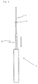
- Fig. 2 shows the pneumatic cylinder connected to the heddle.
- the heddle is coupled to a piston rod 8 of the pneumatic cylinder.
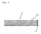
- Fig. 3 shows an interweaving piece 9.
- the interweaving piece has at one end thereof a fabric structure comprising weft threads 10 and warp threads 11. In a remaining portion of the interweaving piece all warp threads are removed to leave the weft threads 10 with a crimp.
- the interweaving piece has a width corresponding to that of a woven seam and a length longer than the transversal width of the fabric to be joined.
- Fig. 4 shows the interweaving piece held on a weaving table 18.
- the fabric structure remaining in the interweaving piece is fixed to the weaving table.
- the weft threads with a crimp are extended through the eyes of the heddles and subjected to tensile force by weights 12 connected to one ends of the weft threads.
- the case 7 is mounted on the mobile guide rail of the weaving table.
- Fig. 5 is a view illustrating the seam weaving method according to this invention.
- end portions 14 of the fabric to be joined are arranged to face each other on the weaving table 13.
- the interweaving piece comprising the weft threads is placed between the end portions.
- the case 7 is mounted on the guide rail of the weaving table. The weft threads of the interweaving piece are made to pass through the eyes of the heddles.
- the weft threads are removed from the end portions of the fabric to be joined over the width equal to that of the woven seam to leave the warp threads with a crimp.
- the weft threads passing through the heddles are shifted to form the shed, like the warp threads in an ordinary weaving process.
- the warp threads of the end portions of the fabric are successively introduced into the shed to form a fabric structure.
- the movement of the heddles is controlled so as to form the fabric structure similar to that of the main body of the fabric.
- the weft threads 10 of the interweaving piece serve as the warp threads in the seam weaving operation while the warp threads 15 of the end portions of the fabric serve as the weft threads.
- Fig. 6 shows the top ends of the warp threads which are interwoven.
- the top ends of the warp threads face each other with the weft threads interposed therebetween.
- the facing positions are dispersed to form no linear alignment. With this structure, any problems of marking are prevented.
- the heddles are supported at both upper and lower ends thereof. Accordingly, the heddles can not be manually pushed aside. On the other hand, it is possible to make a particular heddle be upwardly protruded among a mass of the heddles. However, the particular heddle is not swingable because it is supported at both upper and lower ends. Furthermore, the supporting members of the other heddles closely stand and surround the particular heddle. As a result, threading or recovery operation is extremely difficult. Thus, in the Jacquard device, it is impossible to arrange a concentrated mass of the individual heddles in a narrow area.
- weft threads are removed from end zones over a predetermined width to prepare interweaving portions exclusively comprising warp threads with a crimp.
- the interweaving portions with the warp threads alone are folded back and placed on a weaving table to face each other with a predetermined distance left therebetween.
- An interweaving piece is made of the same kind of fabric as the fabric to be joined and has a width corresponding to that of a woven seam and a length longer than the transversal width of the fabric to be joined.
- the interweaving piece has a fabric structure at one end thereof with warp threads retained therein while a remaining area of the interweaving piece contains only weft threads with a crimp with warp threads removed therefrom.
- the interweaving piece is fixedly located in a space defined between the interweaving portions facing each other so that the one end with the fabric structure is positioned at a seam weaving starting side and the weft threads are parallel to the weaving table.
- the weft threads of the interweaving piece are made to pass through the eyes of the heddles.
- the weft threads are subjected to tensile force which is produced by weights attached to one end of the weft threads.
- the heddles are individually connected to pneumatic cylinders.
- the heddles are supported at one ends coupled to the top ends of piston rods of the pneumatic cylinders.
- Electromagnetic valves of the pneumatic cylinders are operated in response to a signal delivered from a control unit and move the heddles vertically upwardly and downwardly. Consequently, the weft threads of the interweaving piece passing through the heddles are shifted vertically upwardly and downwardly to form the shed.
- the warp threads of both end portions of the fabric to be joined are introduced into the shed.
- seam weaving operation is carried out to integrally join the both end portions by forming a fabric.
- a woven seam has a structure similar to the other portion of the fabric.
- the weft threads of the interweaving piece are shifted by heddles to form the shed while the warp threads of the main body of the fabric are introduced into the shed.
- the warp threads are shifted by heddles to form the shed while the weft threads are introduced into the shed.
- the interweaving piece is prepared by removing the warp thread to leave the weft threads alone.
- seam weaving operation can also be carried out with the interweaving piece prepared by removing the warp threads to leave the weft threads alone.
- the warp threads are removed from the both ends of the fabric to be joined over the width corresponding to that of the woven seam to form the interweaving portion comprising the weft threads alone.
- Use may also be made of a combination of an interweaving piece prepared by the weft threads alone and interweaving portions formed by the warp threads alone.
- the seam weaving operation can be carried out whichever thread is introduced into the shed.
- the pneumatic cylinders to be used have a diameter between 2.5mm-5mm.
- the pneumatic cylinders are driven by electromagnetic valves which are operated in response to a signal from a control unit having a memory for memorizing a structure of a woven seam.
- a cooling device such as a fan.
- Fig. 1 The system in Fig. 1 according to this invention was used to join the fabric consisting of single warp threads and double weft threads as shown in Table 1.
- a woven seam was formed by 150mm per hour.
- the heddles are connected in one-to-one correspondence to pneumatic cylinders and moved thereby. Since the pneumatic cylinders are very small, a large number of the pneumatic cylinders can be arranged in a seam weaving portion which is narrow. The pneumatic cylinders are driven by electromagnetic valves to cause stroke movement. Accordingly, the shedding system is very compact and can be arranged in the upper or the lower portion of the seam weaving portion.
- the heddles are supported at one ends thereof so that shedding system for seam weaving operation is small-sized and recovery of a thread snapping accident is facilitated. It is possible to readily and accurately form a woven seam having a desired structure.
Landscapes
- Engineering & Computer Science (AREA)
- Textile Engineering (AREA)
- Looms (AREA)
- Woven Fabrics (AREA)
- Threshing Machine Elements (AREA)
- Soil Working Implements (AREA)
- Physical Deposition Of Substances That Are Components Of Semiconductor Devices (AREA)
- Fluid-Pressure Circuits (AREA)
- Paper (AREA)
- Treatment Of Fiber Materials (AREA)
Claims (10)
- Système de formation de la foule dans une machine de couture comprenant une pluralité de lices (1), caractérisé en ce que chaque lice (1) est supportée seulement à une extrémité, et a un oeillet (5) à l'autre extrémité, en ce que chaque lice (1) est individuellement couplée à une tige de piston (8) d'une pluralité de vérins pneumatiques, et en ce qu'il comprend en outre une pluralité d'électrovannes (3) connectées individuellement audit vérin pneumatique, et une unité de commande destinée à produire un signal pour actionner lesdites électrovannes (3), lesdites lices (1) étant déplacées verticalement vers le haut et vers le bas par le mouvement alternatif desdits vérins pneumatiques (8) de manière à former la foule dans un groupement de fils, lesdits fils passant individuellement dans les oeillets (5) desdites lices.
- Système de formation de la foule selon la revendication 1, comprenant en outre un ventilateur de refroidissement (4) destiné à refroidir lesdites électrovannes (3).
- Système de formation de la foule selon la revendication 1 ou 2, dans lequel ladite unité de commande comprend une mémoire destinée à mémoriser une structure d'étoffe.
- Système de formation de la foule selon l'une quelconque des revendications 1 à 3, dans lequel chacune desdites lices (1) comprend un corps solide formé de métal ou de plastique.
- Système de formation de la foule selon l'une quelconque des revendications précédentes, dans lequel lesdites lices (1) sont faites d'une matière métallique ou d'une matière plastique moulée selon une forme ayant une section arquée ou une section ondulante.
- Procédé pour joindre les extrémités d'une étoffe par une couture tissée afin de former une étoffe sans fin, comprenant les étapes consistant à : (a) préparer une pièce d'entrelacement (9) qui est faite du même type d'étoffe que ladite étoffe à joindre et qui a une largeur correspondant à celle de ladite couture tissée et une longueur supérieure à la largeur transversale de ladite étoffe à joindre, ladite pièce d'entrelacement ayant une surface d'extrémité longitudinale qui conserve une structure d'étoffe et une surface restante contenant des fils de trame seuls avec les fils de chaíne enlevés de celle-ci, (b) enlever les fils de trame dans les deux zones d'extrémité de ladite étoffe sur une largeur sensiblement égale à celle de ladite couture tissée pour former des parties d'entrelacement comprenant des fils de chaíne seuls, (c) maintenir lesdites parties d'entrelacement sur un métier à tisser (18) de manière à ce que lesdites parties d'entrelacement soient face à face à une distance égale à la largeur de ladite couture tissée de l'une à l'autre pour définir un intervalle entre elles, et placer ladite pièce d'entrelacement dans ledit intervalle de manière à ce que ladite structure d'étoffe conservée au niveau de ladite surface d'extrémité longitudinale soit positionnée à une extrémité transversale desdites parties d'entrelacement, (d) faire passer lesdits fils de trame de ladite pièce d'entrelacement dans les oeillets (5) d'une pluralité de lices (1) d'un système de formation de la foule selon l'une quelconque des revendications précédentes, (e) fixer des poids (12) à l'autre extrémité desdits fils de trame de ladite pièce d'entrelacement pour appliquer une force de traction auxdits fils de trame, (f) actionner lesdites vannes électromagnétiques (3) connectées auxdits vérins pneumatiques à l'aide d'un signal provenant d'une unité de commande, (g) déplacer lesdites lices (1) verticalement vers le haut et vers le bas par le mouvement alternatif desdits vérins pneumatiques de manière à former la foule dans un groupement desdits fils de trame passant dans lesdits oeillets (5) desdites lices (1), et (h) introduire lesdits fils de chaíne desdites parties d'entrelacement dans la foule pour former ladite couture tissée.
- Procédé pour joindre les extrémités d'une étoffe par une couture tissée afin de former une étoffe sans fin, comprenant les étapes consistant à : (a) préparer une pièce d'entrelacement (9) qui est faite du même type d'étoffe que ladite étoffe à joindre et qui a une largeur correspondant à celle de ladite couture tissée et une longueur supérieure à la largeur transversale de ladite étoffe à joindre, ladite pièce d'entrelacement (9) ayant une surface d'extrémité longitudinale qui conserve une structure d'étoffe et une surface restante contenant des fils de chaíne seuls avec les fils de trame enlevés de celle-ci, (b) enlever les fils de chaíne dans les deux zones d'extrémité de ladite étoffe sur une largeur sensiblement égale à celle de ladite couture tissée pour former des parties d'entrelacement comprenant des fils de trame seuls, (c) maintenir lesdites parties d'entrelacement sur un métier à tisser (18) de manière à ce que lesdites parties d'entrelacement soient face à face à une distance égale à la largeur de ladite couture tissée de l'une à l'autre pour définir un intervalle entre elles, et placer ladite pièce d'entrelacement (9) dans ledit intervalle de manière à ce que ladite structure d'étoffe conservée au niveau de ladite surface d'extrémité longitudinale soit positionnée à une extrémité transversale desdites parties d'entrelacement, (d) faire passer lesdits fils de chaíne de ladite pièce d'entrelacement dans les oeillets (5) d'une pluralité de lices (1) d'un système de formation de la foule selon l'une quelconque des revendications 1 à 5, (e) fixer des poids (12) à l'autre extrémité desdits fils de chaíne de ladite pièce d'entrelacement pour appliquer une force de traction auxdits fils de chaíne, (f) actionner les vannes électromagnétiques (3) connectées auxdits vérins pneumatiques à l'aide d'un signal provenant d'une unité de commande, (g) déplacer lesdites lices (1) verticalement vers le haut et vers le bas par le mouvement alternatif desdits vérins pneumatiques de manière à former la foule dans un groupement desdits fils de chaíne passant dans lesdits oeillets (5) desdites lices (1), et (h) introduire lesdits fils de trame desdites parties d'entrelacement dans la foule pour former ladite couture tissée.
- Procédé selon la revendication 6 ou 7, dans lequel les fils desdites parties d'entrelacement à introduire dans la foule ont une ondulation similaire à celle des fils de départ qui sont introduits dans la foule lorsque ladite étoffe à joindre est initialement tissée.
- Procédé selon l'une quelconque des revendications 6 à 8, dans lequel ladite couture tissée est faite de manière à avoir une structure d'étoffe similaire à celle de l'autre partie de ladite étoffe par l'utilisation d'une mémoire qui est incluse dans ladite unité de commande dudit système de formation de la foule et qui est destinée à mémoriser ladite structure d'étoffe.
- Procédé selon l'une quelconque des revendications 6 à 9, dans lequel des cordes chargées sont connectées auxdits fils de trame de ladite pièce d'entrelacement passant à travers lesdits oeillets (5) desdites lices (1) pour appliquer une force de traction auxdits fils de trame pendant l'opération de tissage de ladite structure d'étoffe.
Applications Claiming Priority (2)
| Application Number | Priority Date | Filing Date | Title |
|---|---|---|---|
| JP307252/91 | 1991-09-10 | ||
| JP3307252A JPH0571036A (ja) | 1991-09-10 | 1991-09-10 | 一端を支持した綜絖を用いた開口装置及びこの装置を用いた織り継ぐ方法 |
Publications (3)
| Publication Number | Publication Date |
|---|---|
| EP0536899A2 EP0536899A2 (fr) | 1993-04-14 |
| EP0536899A3 EP0536899A3 (en) | 1993-07-14 |
| EP0536899B1 true EP0536899B1 (fr) | 1998-12-23 |
Family
ID=17966870
Family Applications (1)
| Application Number | Title | Priority Date | Filing Date |
|---|---|---|---|
| EP92308191A Expired - Lifetime EP0536899B1 (fr) | 1991-09-10 | 1992-09-09 | Système de formation de la foule |
Country Status (6)
| Country | Link |
|---|---|
| US (1) | US5360038A (fr) |
| EP (1) | EP0536899B1 (fr) |
| JP (1) | JPH0571036A (fr) |
| AT (1) | ATE174974T1 (fr) |
| CA (1) | CA2077878C (fr) |
| DE (1) | DE69227971T2 (fr) |
Cited By (1)
| Publication number | Priority date | Publication date | Assignee | Title |
|---|---|---|---|---|
| DE10305016A1 (de) * | 2003-02-07 | 2004-09-16 | Groz-Beckert Kg | Vorspanneinrichtung für Weblitzen |
Families Citing this family (11)
| Publication number | Priority date | Publication date | Assignee | Title |
|---|---|---|---|---|
| US5494080A (en) * | 1991-09-10 | 1996-02-27 | Nippon Filcon Co., Ltd. | Arcuate heddle and shedding system employing an arcuate heddle |
| CH690037A5 (de) * | 1995-08-30 | 2000-03-31 | Agm Ag Mueller | Fachbildeeinrichtung für Webmaschinen. |
| US5738151A (en) * | 1996-08-13 | 1998-04-14 | Asten, Inc. | Seam loop formation device and method of operation |
| US5735315A (en) * | 1996-09-11 | 1998-04-07 | A.E. Petsche Company, Inc. | Wire loom dobby |
| SE512567C2 (sv) * | 1998-08-31 | 2000-04-03 | Texo Ab | Styrarrangemang vid skaftramsvävmaskin eller vävmaskinsarrangemang innefattande sådan maskin |
| SE512568C2 (sv) * | 1998-08-31 | 2000-04-03 | Texo Ab | Skaftramsvävmaskin med varptrådsuppsättningar i två skikt samt två varptrådsuppsättningar i vändvecksskikt |
| SE512569C2 (sv) * | 1998-08-31 | 2000-04-03 | Texo Ab | Vävmaskinsarrangemang med metod, anordning och användning samt rundvävd produkt framställd med arrangemanget |
| FR2794140B1 (fr) | 1999-05-31 | 2001-07-13 | Staubli Sa Ets | Mecanique d'armure de type jacquard et metier a tisser equipe d'une telle mecanique |
| ITMI20030537U1 (it) * | 2003-11-19 | 2005-05-20 | Startes Jacquard S P A | Telaio tessile dotato di un sostema di raffreddamento |
| JP5937838B2 (ja) * | 2011-07-12 | 2016-06-22 | 日本フイルコン株式会社 | 工業用多層織物の接合用ループ構造 |
| KR101944019B1 (ko) * | 2018-09-20 | 2019-01-30 | (주)동일캔바스엔지니어링 | 무한 주행 벨트용 직기 |
Citations (1)
| Publication number | Priority date | Publication date | Assignee | Title |
|---|---|---|---|---|
| JPH0369626A (ja) * | 1989-08-04 | 1991-03-26 | Koji Nakazawa | 紋織機 |
Family Cites Families (10)
| Publication number | Priority date | Publication date | Assignee | Title |
|---|---|---|---|---|
| IT938965B (it) * | 1971-10-06 | 1973-02-10 | Romano E | Dispositivo operante sostanzialmen te pneumaticamente per il movimento di sollevamento ed abbassamento dei fili di ordito nei telai di tessitu ra |
| IT1105933B (it) * | 1977-07-26 | 1985-11-11 | Brochier Soieries J | Apparecchiatura per il comando dei movimenti dei fili di ordito in un telaio di tessitura |
| CH631755A5 (de) * | 1978-09-26 | 1982-08-31 | Braecker Ag | Webelitze. |
| DE2939421C2 (de) * | 1979-09-28 | 1981-09-24 | Grosse Webereimaschinen Gmbh, 7910 Neu-Ulm | Vorrichtung zum Heben und Senken der Kettfäden einer Webmaschine |
| DE3025909C2 (de) * | 1980-07-09 | 1983-07-14 | Hermann Wangner Gmbh & Co Kg, 7410 Reutlingen | Verfahren und Vorrichtung zum Herstellen einer Webnaht zwischen zwei Gewebeenden |
| CA1209442A (fr) * | 1983-05-02 | 1986-08-12 | Raymond Saint-Hilaire | Harnais et lisses pour metier a tisser |
| DE3446941A1 (de) * | 1984-12-21 | 1986-07-03 | F. Oberdorfer, 7920 Heidenheim | Verfahren zur herstellung einer stecknaht zum endlosmachen eines gewebebandes und nahtungsmaschine |
| DE3833480A1 (de) * | 1988-02-23 | 1989-08-31 | Textima Veb K | Elektromagnetische platinenauswahlsteuerung fuer die jacquardmaschine einer webmaschine |
| JPH01292135A (ja) * | 1988-05-13 | 1989-11-24 | Murata Mach Ltd | ドビー機 |
| DE4030464A1 (de) * | 1990-09-26 | 1992-04-02 | Oberdorfer Fa F | Elektro-pneumatische fachbildungseinrichtung, insbesondere fuer nahtmaschinen |
-
1991
- 1991-09-10 JP JP3307252A patent/JPH0571036A/ja active Pending
-
1992
- 1992-09-04 US US07/939,472 patent/US5360038A/en not_active Expired - Fee Related
- 1992-09-09 AT AT92308191T patent/ATE174974T1/de not_active IP Right Cessation
- 1992-09-09 DE DE69227971T patent/DE69227971T2/de not_active Expired - Fee Related
- 1992-09-09 CA CA002077878A patent/CA2077878C/fr not_active Expired - Fee Related
- 1992-09-09 EP EP92308191A patent/EP0536899B1/fr not_active Expired - Lifetime
Patent Citations (1)
| Publication number | Priority date | Publication date | Assignee | Title |
|---|---|---|---|---|
| JPH0369626A (ja) * | 1989-08-04 | 1991-03-26 | Koji Nakazawa | 紋織機 |
Cited By (2)
| Publication number | Priority date | Publication date | Assignee | Title |
|---|---|---|---|---|
| DE10305016A1 (de) * | 2003-02-07 | 2004-09-16 | Groz-Beckert Kg | Vorspanneinrichtung für Weblitzen |
| DE10305016B4 (de) * | 2003-02-07 | 2007-02-01 | Groz-Beckert Kg | Vorspanneinrichtung für Weblitzen |
Also Published As
| Publication number | Publication date |
|---|---|
| JPH0571036A (ja) | 1993-03-23 |
| CA2077878A1 (fr) | 1993-03-11 |
| EP0536899A2 (fr) | 1993-04-14 |
| EP0536899A3 (en) | 1993-07-14 |
| ATE174974T1 (de) | 1999-01-15 |
| CA2077878C (fr) | 1998-06-09 |
| DE69227971D1 (de) | 1999-02-04 |
| US5360038A (en) | 1994-11-01 |
| DE69227971T2 (de) | 1999-05-12 |
Similar Documents
| Publication | Publication Date | Title |
|---|---|---|
| EP0536899B1 (fr) | Système de formation de la foule | |
| US6418974B1 (en) | Woven fabric using three dimensional and flat weave in combination, related methods and filter element | |
| US5435352A (en) | Weaving method for in-plane multiaxial thick woven fabrics | |
| US4756340A (en) | Jacquared double plush fabric | |
| JPH06504593A (ja) | 多軸織り | |
| US5582213A (en) | Loop-forming apparatus in a weaving machine for pile fabric | |
| US4958663A (en) | Woven multi-layer angle interlock fabrics having fill weaver yarns interwoven with relatively straight extending warp yarns | |
| US4416310A (en) | Double-lift Jacquard mechanism | |
| JPH11512495A (ja) | 糸の横方向往復運動の選択的制御装置 | |
| US4557025A (en) | Automatic seaming machine | |
| US5699836A (en) | Method and apparatus for manufacturing slotted webbing on a needle loom | |
| EP0957191B1 (fr) | Procédé et dispositif pour la fabrication d'articles textiles | |
| US5494080A (en) | Arcuate heddle and shedding system employing an arcuate heddle | |
| GB2312440A (en) | Jacquard mechanism | |
| EP0228029B1 (fr) | Dispositif pour former le poil dans les métiers à tisser | |
| US4077437A (en) | Apparatus for forming a double catch thread narrow weave | |
| US6953067B2 (en) | Method for deflecting a warp thread during weaving and a weaving machine | |
| US5386854A (en) | Compact jacquard type seam-weaving machine | |
| US5172733A (en) | Weaving thick fabric by lifting cloth fell | |
| US5909750A (en) | Multiple stage device and method for manufacturing a woven fabric | |
| JPH0665772B2 (ja) | 三次元織物の製造方法及び装置 | |
| JPH02191742A (ja) | 三次元織物及びその製造方法 | |
| JP2002266197A (ja) | 表裏異柄織物とその重ね織方及び重ね織機 | |
| GB2218715A (en) | Double lift open shed Jacquard | |
| GB1584532A (en) | Apparatus for producing woven cloth |
Legal Events
| Date | Code | Title | Description |
|---|---|---|---|
| PUAI | Public reference made under article 153(3) epc to a published international application that has entered the european phase |
Free format text: ORIGINAL CODE: 0009012 |
|
| AK | Designated contracting states |
Kind code of ref document: A2 Designated state(s): AT CH DE FR GB IT LI SE |
|
| PUAL | Search report despatched |
Free format text: ORIGINAL CODE: 0009013 |
|
| AK | Designated contracting states |
Kind code of ref document: A3 Designated state(s): AT CH DE FR GB IT LI SE |
|
| 17P | Request for examination filed |
Effective date: 19930723 |
|
| 17Q | First examination report despatched |
Effective date: 19931112 |
|
| GRAG | Despatch of communication of intention to grant |
Free format text: ORIGINAL CODE: EPIDOS AGRA |
|
| GRAG | Despatch of communication of intention to grant |
Free format text: ORIGINAL CODE: EPIDOS AGRA |
|
| GRAH | Despatch of communication of intention to grant a patent |
Free format text: ORIGINAL CODE: EPIDOS IGRA |
|
| GRAH | Despatch of communication of intention to grant a patent |
Free format text: ORIGINAL CODE: EPIDOS IGRA |
|
| GRAA | (expected) grant |
Free format text: ORIGINAL CODE: 0009210 |
|
| AK | Designated contracting states |
Kind code of ref document: B1 Designated state(s): AT CH DE FR GB IT LI SE |
|
| PG25 | Lapsed in a contracting state [announced via postgrant information from national office to epo] |
Ref country code: LI Free format text: LAPSE BECAUSE OF FAILURE TO SUBMIT A TRANSLATION OF THE DESCRIPTION OR TO PAY THE FEE WITHIN THE PRESCRIBED TIME-LIMIT Effective date: 19981223 Ref country code: FR Free format text: LAPSE BECAUSE OF FAILURE TO SUBMIT A TRANSLATION OF THE DESCRIPTION OR TO PAY THE FEE WITHIN THE PRESCRIBED TIME-LIMIT Effective date: 19981223 Ref country code: CH Free format text: LAPSE BECAUSE OF FAILURE TO SUBMIT A TRANSLATION OF THE DESCRIPTION OR TO PAY THE FEE WITHIN THE PRESCRIBED TIME-LIMIT Effective date: 19981223 |
|
| REF | Corresponds to: |
Ref document number: 174974 Country of ref document: AT Date of ref document: 19990115 Kind code of ref document: T |
|
| REG | Reference to a national code |
Ref country code: CH Ref legal event code: EP |
|
| REF | Corresponds to: |
Ref document number: 69227971 Country of ref document: DE Date of ref document: 19990204 |
|
| ITF | It: translation for a ep patent filed | ||
| PG25 | Lapsed in a contracting state [announced via postgrant information from national office to epo] |
Ref country code: SE Free format text: LAPSE BECAUSE OF FAILURE TO SUBMIT A TRANSLATION OF THE DESCRIPTION OR TO PAY THE FEE WITHIN THE PRESCRIBED TIME-LIMIT Effective date: 19990323 |
|
| EN | Fr: translation not filed | ||
| REG | Reference to a national code |
Ref country code: CH Ref legal event code: PL |
|
| PLBE | No opposition filed within time limit |
Free format text: ORIGINAL CODE: 0009261 |
|
| 26N | No opposition filed | ||
| PGFP | Annual fee paid to national office [announced via postgrant information from national office to epo] |
Ref country code: GB Payment date: 20010912 Year of fee payment: 10 Ref country code: AT Payment date: 20010912 Year of fee payment: 10 |
|
| PGFP | Annual fee paid to national office [announced via postgrant information from national office to epo] |
Ref country code: DE Payment date: 20010924 Year of fee payment: 10 |
|
| REG | Reference to a national code |
Ref country code: GB Ref legal event code: IF02 |
|
| PG25 | Lapsed in a contracting state [announced via postgrant information from national office to epo] |
Ref country code: GB Free format text: LAPSE BECAUSE OF NON-PAYMENT OF DUE FEES Effective date: 20020909 Ref country code: AT Free format text: LAPSE BECAUSE OF NON-PAYMENT OF DUE FEES Effective date: 20020909 |
|
| PG25 | Lapsed in a contracting state [announced via postgrant information from national office to epo] |
Ref country code: DE Free format text: LAPSE BECAUSE OF NON-PAYMENT OF DUE FEES Effective date: 20030401 |
|
| GBPC | Gb: european patent ceased through non-payment of renewal fee |
Effective date: 20020909 |
|
| PG25 | Lapsed in a contracting state [announced via postgrant information from national office to epo] |
Ref country code: IT Free format text: LAPSE BECAUSE OF NON-PAYMENT OF DUE FEES Effective date: 20050909 |