EP0536946A2 - Ordinateur à multiprocesseur pour résoudre des ensembles d'équations - Google Patents
Ordinateur à multiprocesseur pour résoudre des ensembles d'équations Download PDFInfo
- Publication number
- EP0536946A2 EP0536946A2 EP92308946A EP92308946A EP0536946A2 EP 0536946 A2 EP0536946 A2 EP 0536946A2 EP 92308946 A EP92308946 A EP 92308946A EP 92308946 A EP92308946 A EP 92308946A EP 0536946 A2 EP0536946 A2 EP 0536946A2
- Authority
- EP
- European Patent Office
- Prior art keywords
- task
- tasks
- matrix
- processing elements
- equations
- Prior art date
- Legal status (The legal status is an assumption and is not a legal conclusion. Google has not performed a legal analysis and makes no representation as to the accuracy of the status listed.)
- Withdrawn
Links
Images


Classifications
-
- G—PHYSICS
- G06—COMPUTING OR CALCULATING; COUNTING
- G06F—ELECTRIC DIGITAL DATA PROCESSING
- G06F17/00—Digital computing or data processing equipment or methods, specially adapted for specific functions
- G06F17/10—Complex mathematical operations
- G06F17/11—Complex mathematical operations for solving equations, e.g. nonlinear equations, general mathematical optimization problems
- G06F17/12—Simultaneous equations, e.g. systems of linear equations
-
- G—PHYSICS
- G06—COMPUTING OR CALCULATING; COUNTING
- G06F—ELECTRIC DIGITAL DATA PROCESSING
- G06F17/00—Digital computing or data processing equipment or methods, specially adapted for specific functions
- G06F17/10—Complex mathematical operations
- G06F17/16—Matrix or vector computation, e.g. matrix-matrix or matrix-vector multiplication, matrix factorization
-
- G—PHYSICS
- G06—COMPUTING OR CALCULATING; COUNTING
- G06F—ELECTRIC DIGITAL DATA PROCESSING
- G06F30/00—Computer-aided design [CAD]
- G06F30/30—Circuit design
- G06F30/36—Circuit design at the analogue level
- G06F30/367—Design verification, e.g. using simulation, simulation program with integrated circuit emphasis [SPICE], direct methods or relaxation methods
Definitions
- the invention relates to computer systems in general and, more particularly, to computer methods and systems for solving sets of equations that can be represented in matrix form.
- Solving sets of equations is useful in, inter alia, mechanics, economics, fluid dynamics and electric circuit simulation.
- Circuit simulation typically involves assembling a set of equations that model the behavior of an electric circuit and then solving such set of equations to learn the value of unknown voltages and currents in the circuit.
- the equations that describe the circuit being simulated are often nonlinear and, for this reason, an iterative technique, such as the Newton Raphson method has typically been used to solve such set of equations.
- Various iterative techniques, including the Newton Raphson method are well known to persons having ordinary skill in the art.
- LUD Lower Upper Decomposirion
- the invention provides a mechanism for a solving set of equations represented in matrix form by using an approach different from the prior art.
- a set of equations can be solved by the present invention more quickly than with previous mechanisms.
- An illustrative embodiment of the invention comprises several processing elements that are interconnected via a communications network.
- the scheduling of the communications between the processors is dictated by a special purpose network processor.
- FIG. 1 shows a schematic diagram of a typical electric circuit to be analyzed by an illustrative embodiment of the invention.
- FIG. 2 shows a set of equations that model the electrical characteristics of the electric circuit in FIG. 1.
- FIG. 3 shows a matrix representation of the set of equations shown in FIG. 2.
- FIG. 4 shows an augmented matrix corresponding to the matrix shown in FIG. 3.
- FIG. 5 shows the zero/non-zero structure of the augmented matrix shown in Fig. 4.
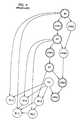
- FIG. 6 shows a task graph for solving the augmented matrix in FIG. 5.
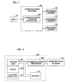
- FIG. 7 shows an overview of an illustrative embodiment of the present invention.
- FIG. 8 shows an overview of a processing element as shown in Fig. 7.
- FIG. 9 shows the mechanism for communicating between the processing elements as shown in Fig. 7.
- FIG. 10 shows an overview of the communications processor as shown in Fig. 8.
- FIG. 11 shows a temporal representation of a task to be performed by the illustrative embodiment.
- FIG. 12 shows options for inserting tasks into the task schedule.
- FIG. 13 shows a task graph for solving the augmented matrix in FIG. 3.
- FIG. 14 shows a schedule for task execution corresponding to the task graph in FIG. 13.
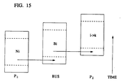
- FIG. 15 shows the timing of a pipelined bus operation on the illustrative embodiment.
- FIG. 16 shows the matrix of Fig. 4 after the first task has been completed.
- FIG. 17 shows the matrix of Fig. 4 after three tasks have been completed.
- FIG. 18 shows the solution matrix corresponding to the circuit of Fig. 1.
- the invention provides a computer system and method for modeling or simulation. It is believed that the illustrative embodiment of the invention to be described will be more easily understood by presenting it in the context of solving an illustrative problem. Although the illustrative embodiment can solve problems arising in diverse fields, the illustrative problem is from electrical engineering. In the next section, the illustrative problem will be presented. Next, an illustrative embodiment of the invention will be presented and finally it will be shown how the illustrative problem can be solved with the illustrative embodiment.
- Electric circuits such as the one represented by the schematic diagram Fig. 1, are typically designed to perform a specific function. While a that deal is known about designing electric circuits, it remains substantially empirical such that fabricated circuits often do not perform as intended by their designers. When the cost of fabrication and testing is low, a circuit can be iteratively designed, fabricated, tested and re-designed until it performs as desired. But when the cost of fabrication and/or testing is high, it is advantageous to verify that the circuit design will perform as intended before it is fabricated.
- Circuit simulation involves building a mathematical model of a circuit based on mathematical models of the circuit elements and on the topology of the circuit. Once the model of the circuit is created, its behavior can be accurately predicted through well-known techniques.
- the electric circuit represented by the schematic diagram in Fig. 1 comprises a voltage source and five resistors.
- the voltage source is 10 volts and that the designer of the circuit intends that in the fabricated circuit the voltage at V 2 is 2.0 volts and the voltage at V 3 is 0.175 volts. To assure that the design will perform as desired, it should be simulated.
- Fig. 1 the electric circuit represented in Fig. 1 can be modeled, according to Kirchhoff's Current Law and Kirchhoff's Voltage Law, and according to the well known technique known as Modified Nodal Analysis, by the set of five equations shown in Fig. 2.
- circuit simulation requires that the equations modeling a circuit be intensively manipulated. To permit them to be more easily manipulated, especially by computer, the equations are typically represented in matrix form. As is well known to persons having ordinary skill in the art, the set of equations in Fig. 2 can be represented in matrix form as shown in Fig. 3.
- LUD involves two operations: normalization and updating.
- normalization involves dividing each after-diagonal element of a row by its diagonal element and updating involves manipulating the rows below the diagonal element of the most recently normalized row. The procedure starts with the top left diagonal element and proceeds down the diagonal.
- the LUD is complete when all of the diagonal elements have been normalized- According to one technique, after LUD is completed, the FE and BS is performed to yield the solution to V 2 and V 3.
- some matrices have a high percentage of zero elements and are therefore said to be "sparse". In contrast, matrices with a low percentage of zero elements are said to be "dense.” While the LUD of a sparse matrix can be identical to the LUD of a dense matrix, the presence of numerous zero elements in the sparse matrix means that many of the operations carried out in performing the LUD unnecessary.
- Forward Elimination is carried out concurrently with the LUD in a manner that is well known to persons having ordinary skill in the art.
- the matrix representing the coefficients is augmented with the vector representing the right hand side of the equations in Fig. 3.
- Fig. 4 presents the augmented matrix corresponding to the matrix of Fig. 3.
- Fig. 5 shows a representation of the matrix of Fig. 4 where an "X" represents the position of a non-zero value in the matrix.
- X represents the position of a non-zero value in the matrix.
- F represents the number of non-zero elements introduced into the matrix in determinable positions. This is significant because it affects the scheduling of the tasks needed for LUD.
- LUD, FE and BS require that each row be successively normalized and that each row that has a non-zero element (i.e., an "X" or an "F") under the diagonal of the row normalized be updated.
- a schedule can be generated of the operations needed to solve the set of equations represented by the matrix.
- a representation of the operations to be performed and their interdependencies can be drawn. Such a representation is known as a "task graph.”
- a task graph can be derived from the patterb of non-zero and fill-in elements in a matrix.
- Fig. 6 presents the task graph associated with the matrix shown in Fig. 5.
- the task graph can be derived by representing each row normalization, row update and back-substitution operation as a task and by noting the interdependencies of the tasks.
- a task is represented in the task graph by a circle circumscribing a description of the operation to be performed.
- a description prefaced with an "N” represents a normalization operation.
- a description prefaced with a “U” represents an update operation and a description prefaced with a "B” represents a back substitution operation.
- the number following the prefixes "N” and “U” designate the row to be operated on.
- the task containing the description "N1” means normalize row 1 and the task containing the description "U2W1 " means update row 2 with information from row 1.
- the pair of numbers following the prefix "B” is the row and column, respectively, of the element in the matrix involved in back substitution.
- a given task can only be performed when all of the preceding tasks that feed information to it have been performed.
- the task graph When, as in Fig. 6, the task graph indicates that two or more tasks are independent, the task graph can be completed more rapidly by performing those tasks in parallel.
- Fig. 7 presents an overview of the illustrative embodiment of the invention. It is based on a distributed memory multiprocessor system and consists of three processing elements 707 ("PE"s), a communication network 703 ("CN") that is controlled by a communication network controller 705 (“CNC”) and a host 701 processor.
- PE processing elements
- CN communication network
- CNC communication network controller
- host 701 processor there are three PEs but it will be obvious to persons having ordinary skill in the art how to modify the design to have a different number of PEs.
- the CNC provides an interface to the host but in other embodiments the host may interface costly with either a PE or a portion of the CN.
- the CNC controls the CN and the communication processor 809 within each PE.
- Each PE has a communication processor that provides an interface to the communication network, an integer unit that is responsible for address calculation, a floating point unit, a cache for holding the rows just normalized, and random access memory to hold a portion of the matrix.
- the host processor executes the preprocessing necessary to construct the task graph and a task schedule.
- An initialization program is executed on the host.
- Each of the processing elements in the system has an initialization control signal that forces it to read in data from the communication network into memory. Once the program and data have been loaded into the processing elements they can begin to perform tasks.
- the CNC 903 handles communication between the host 909 and the processing elements 905 as well as controlling a sequencing unit.
- the sequencing unit is within the CNC and takes a communication schedule that was generated during preprocessing.
- the communication schedule is used to control communication between the processing elements.
- a processing element 905 can therefore assume that information that it transmits to the communication network 901 will be routed correctly by the communication network controller 903. More specifically, the communication processor 907 within the processing element 905 holds the information until the communication network controller indicates that it may be placed on the communication network.
- the communication network can be implemented.
- One option includes using a crossbar switch.
- Other options use ring communication systems or a bus.
- Simulation studies presented by R. Telichevesky, P. Agrawal and J. Trotter in "Fast Scheduling Schemes for Efficient Sparse Matrix Factorization on Multiprocessors," I.E.E.E. Proceedings ICCD 91, Boston (1991) indicate that a bus system running at half the processing elements speed is adequate for 16 processors when as in one embodiment of the invention the Intel 1860 microprocessor is used as the processor in the processing element
- the bus scheme has the advantage of being easy to implement and being able to broadcast to multiple processing elements.
- the Processing Element 707 is the main compute engine for performing tasks. Hence, it contains a number of resources that are used to communicate and to evaluate the various functions. It has a wide data bus (64 bits) that allows a double precision floating point value to be read in quickly. It contains an 8K data cache, which is enough to hold a source row and its index values.
- the instruction cache can be used to hold the code for the normalization and the update.
- the main memory only holds the precompiled instruction list that tells the processor which rows to normalize and update.
- the integer unit can be operated in parallel with the floating point unit for address calculation.
- the floating point unit can be used in a pipelined multiply-add mode (this is the core operation of the update), increasing its throughput.
- the PE must be able to manipulate integers for computing the addresses of the various elements in the data structure.
- High speed memory or cache is used for storing matrix rows and their indices.
- a custom VLSI integrated circuit could be specifically designed for these tasks.
- a special purpose processor with a microcontroller and a high speed specialized floating point unit could be used.
- any of the general purpose microprocessors that have cache storage and a floating point unit could be used.
- the integer unit 803 calculates the addresses for the memory system and implements the basic branch and control instructions of the program The use of the integer unit to calculate the various addresses should not adversely affect the speed of the floating point processor.
- the processing element has a cache 805 large enough to hold the data representing one or more matrix rows. This allows for efficient storage of the source row that is used to update other rows of the matrix with higher row numbers.
- the processing element includes a high speed floating point unit 807 to handle all of the necessary arithmetic computations. Double precision is preferred for accurate circuit simulation.
- the memory system 811 allows random access to the data representing the rows in the matrix. Because the memory is accessed randomly and at high speed, static memory is preferred to achieve the fastest possible speed.
- the communication processor 809 is the part of the processing element 707 that provides the interface to the communication network 703.
- the communication processor contains a bi-directional data buffer which allows the processing element to transmit data to the communication processor and vice versa.
- the advantage of the buffer is that the processing element can perform computations while the data is queued for transmission to the communication network and while data is being received.
- the data representing elements in the matrix is transmitted over the communication network in untagged form. Therefore, the processing element relies on the context of the data to indicate its meaning.
- the buffer is implemented as a first-in first-out (FIFO) queue and is shown in Figure 10.
- the communication bus is 96 bits wide. In other embodiments the communication bus can have a different width.
- the processing elements internal bus is 64 bits wide but can be other widths equal to or not equal to the communication bus width.
- the computer described above can be used to solve matrices. Because the computer has three processing elements, each with its own memory, the rows of the matrix are distributed among the various processing elements. Although the operations on each row are somewhat independent there is some information that needs to be communicated between the processing elements. Thus a communication takes place when a processor needs the result of a calculation performed by another processor.
- Fig. 13 presents a task graph indicating that different tasks are to be executed on different processors.
- a task performed on the first processing element is represented by a circle.
- a task performed by the second processing element is represented by a square and a task performed on the third processing element is represented by a triangle.
- An inter-processing element communication over the communication network is represented in Fig. 13 by a dashed line between tasks.
- a task can be executed when all of the tasks that it is dependent on have been completed. Thus, it is possible to schedule a subset of the tasks to be performed by each of the processing elements. In addition, it is possible to schedule a list of communications that have to occur between processing elements.
- the set of equations can be solved by providing each processor with a list of tasks it must execute and providing the scheduler with a list of communications, both of which can be obtained from the task graph.
- Fig. 14 shows the schedule obtained from the task graph of Fig. 13.
- the LU decomposition of the matrix A can be represented as a series of operations of three basic types:
- a row-wise normalization is defined as: For all non-zero a kj , a kj ⁇ a kj ⁇ p k , j > k and the row-wise update , denoted by k ⁇ i , corresponding to row i being updated by row k , is defined as: For all non-zero a kj , a ij ⁇ a ij ⁇ a ik ⁇ a kj , i,j > k
- k a source row and to i as a destination or target or fanout row in Equation 3.
- Rules (i) through (iii) establish dependencies in the strong sense with respect to row-wise operations, i.e. one operation cannot start fetching operands before the other has finished storing all results, which usually is a bad characteristic for pipelined systems.
- Rule (iv) permits a row update task to start as soon as the first result of the normalize operation is available, provided both pipelines run at the same speed. This rule establishes a new type of dependency which we shall refer to as a mild dependency.
- Each node ⁇ V corresponds to a pipelined task, as shown in Figure 14.
- Figure 14 depicts the execution of the task in a real processor.
- the last piece of data is fed into the pipeline and the processor is ready to start feeding the pipeline some data corresponding to a new task.
- Figure 6 shows the task graph that represents the LU Decomposition of the sparse matrix depicted in Figure 5.
- the pipeline latency is 1 cycle and the throughput is 1 cycle for multiply-add operations and a division (nonpipelined) takes 1 cycle.
- a task is called an initial or ⁇ - task if it does not depend on any previous operations and is called a terminal or ⁇ -task if no task depends on it.
- Every task has an associate set of dependency paths R ⁇ ,i .
- Each element R ⁇ ,i k ⁇ R ⁇ ,i is itself a set of vertices that are traversed in the path that connects to any ⁇ -node (and includes them).
- each set R ⁇ ,i k an integer function S ( R ⁇ ,i k ) that represents the cardinality of R ⁇ ,i k .
- a task is said to be at level h i if among all the paths R ⁇ ,i k connecting the initial tasks to the largest one contains h i ; elements, or
- the height H of a task graph is defined as the level of the vertex at the highest level, or
- the height of the task graph is associated with the minimal completion time of the matrix decomposition. Task graphs that are short and stout are expected to exploit parallelism better than those that are tall and skinny. In the example in Figure 6, the height of the task graph is seven.
- R ⁇ ,i k is any path starting at an ⁇ -node and finishing at and cost ( ) can be either c j (resource cost), p j (pipeline latency rime) or even c j + p j , depending on the type of the dependencies on that occur while traversing the path R ⁇ ,i k .
- the earliest completion time D for the decomposition is defined as the completion time of the node with the largest d i , or
- the remaining completion time is actually a measure of how important is the early execution of a given task, as it is known that once the task is finished, the minimum time for completion of all the tasks that depend on is ⁇ i .
- ⁇ i the minimum time for completion of all the tasks that depend on is ⁇ i .
- ⁇ for ⁇ -tasks is zero.
- the greedy technique works as follows. Each processor will execute all assigned tasks that are ready for execution, i.e., all tasks on which it depends on have already finished. Otherwise, the processor will stall. This technique is very fast and yields in almost all cases better results than the level approach. However, it requires a more complex synchronization mechanism among processors. In the following, we give a brief description of the technique.
- each node contains a list of tasks on which it depends.
- the dependencies correspond to the arc directions that are opposite to those shown in Figure 6.
- D 0
- the levels in the task graph range from 1 to H, H being the highest level. The technique proceeds as:
- each task has a completion time ⁇ i as computed in Section 4.2.2.
- a timestamp t i which represents the earliest time the task can be executed considering its data dependencies and the processor allocation.
- each node contains information about the number of dependencies nd i that must be satisfied before is enabled.
- Each processor p has a local timer f p which holds the time the last scheduled task is completed.
- An auxiliary t v register will contain the total time necessary to complete the decomposition.
- Step 1 The scheduling scheme proposed in Step 1 is so simple that one might ask if it is correct, as it is not obvious that it will generate deadlock-free code.
- the following proof, by contradiction, provides necessary and sufficient conditions for a deadlock-free code: Theorem 1 This proof is divided into three parts, the first corresponding to the uniprocessor case and the remaining two treat interprocessor deadlocks.
- Figure 12 depicts four possible timing situations, which might occur if we try to insert before .
- t V the completion time for the vertical technique.
- T the sequential execution time
- t opt represents the barrier to the amount of parallelism available during the LU decomposition and corresponds to the minimum completion time due to partitioning. This can be easily computed for each row of the matrix by determining the dependencies and the number of operations needed to update a given row.
- Table 1 lists the simulation results for the LU decomposition using the techniques previously described.
- level-based and greedy scheduling we reproduce the results reported in our previous work
- we used a very simple cost function, in which each elemental operation takes 1 cycle and we assume no pipelining ( p i 0 for all i ).
- the ⁇ -greedy scheduling yields better results in 80% of the cases, as it combines the advantages of both the vertical and the greedy schemes.
- the only two cases in which the bare greedy technique outperforms the ⁇ -greedy is for iir12 and mfr with a moderate number of processors.
- the critical path does not play an important role, as efficiency is dominated by the greedy allocation of tasks with a minimum slack.
- ⁇ 3.total cost D ⁇ P
- Table 2 contains the results, in mili-seconds for different hardware configurations.
- i860 represents a system built with Intel i860 processors running at 40Mhz.
- W g and W s represent systems built with a Weitek FPU and general purpose controller or a special purpose controller running at 20Mhz.
- B g and B s represent systems that contain a Bit FPU and a general or special purpose controller running at a 100Mhz, if it could be built. For the Bit FPU we changed the scheduling algorithm in order to properly model the Division Unit available in the chip.
- the circuit of Fig. 1 can be modeled by the set of equations shown in Fig. 2 which are also represented in matrix form as shown in Fig. 3.
- the zero/non-zero structure of the matrix, shown in Fig. 5, is used to determine the normalization, update and back-substitution tasks necessary to solve the set of equations represented by the matrix.
- These tasks can be scheduled to allow more than one processing element in a multiprocessing system to execute the tasks in parallel. Recall that the tasks are based on row level operations and therefore whole rows of the matrix are distributed amongst the respective processing elements.
- the scheduler first assigns a cost to each task in the task graph.
- Fig. 13 depicts a task graph with cost values of p and c associated with each task.
- the cost, p of the N1 task is 1 because the results of task N1 become available for use by other tasks after one time unit.
- the total cost of a task is equal to p plus c which is represented by the length in time of the associated rectangle as shown in Fig. 14.
- a metric, ⁇ called the "earliest completion time.
- This metric indicates the least amount of time in which the rest of the task graph could be computed were there an infinite amount of processing resources available.
- a value of ⁇ is assigned to each task in the graph beginning at the terminal tasks (e.g., task B2,3) and proceeding toward the initial tasks (e.g., task N1 and task N4).
- the schedule is then derived by taking the set of tasks that are to be executed on each processing element, and for that processing element scheduling the tasks to be executed in reverse order of ⁇ .
- a schedule of communications is determined which is used by the communication network controller to sequence the communications on the communication network.
- Fig. 14 shows a schedule of the tasks to be executed for each of the three processors and the sequence of communications that is necessary to communicate the data between processing elements.
- a list of the tasks and the instructions necessary to execute those tasks is transmitted from the host to each of the processing elements.
- the rows of the matrix are transmitted from the host to the respective processing elements responsible for operating on the row.
- a list representing the sequence of communications to be carried by the communication network is transmitted from the host to the communication network controller.
- the first task executed is N1 (i.e., the normalization of row 1) on processing element P1 (represented by a circle).
- the values in the matrix after this task has been completed are shown in Fig. 16.
- the result of the N1 task is transmitted by P1 to processing element P2, represented by a square. Note that the scheduling of the transmittal is dictated by the communication network controller.
- task U2W1 depends on the data generated by task N1 and can start executing as the data becomes available.
- the task U5W1 is executed next on P2 and it uses the same data transmitted from P1 previously.
- the values of the matrix after these three tasks have been executed is shown in Fig. 17.
- the data from task N4, generated on processing element P1 is needed by both P2 and P3 to execute tasks B2,4, B3,4 and U5W4.
- the communication network controller causes the data to be broadcast to both the processing elements P2 and P3.
- the memory of the processing elements contains, in aggregate, the solution vector (i.e., the solution to the set of equations).
- the matrix of Fig. 18 shows the matrix after all the tasks have been executed and the solution vector is then the last column of the matrix. This is read from the computer by the host.
- the voltages for V 2 and V 3 are determined to be 1.95 and 1.77 volts respectively.
Landscapes
- Engineering & Computer Science (AREA)
- Physics & Mathematics (AREA)
- General Physics & Mathematics (AREA)
- Mathematical Physics (AREA)
- Theoretical Computer Science (AREA)
- Mathematical Analysis (AREA)
- Pure & Applied Mathematics (AREA)
- Computational Mathematics (AREA)
- Mathematical Optimization (AREA)
- Computer Hardware Design (AREA)
- Data Mining & Analysis (AREA)
- General Engineering & Computer Science (AREA)
- Algebra (AREA)
- Databases & Information Systems (AREA)
- Software Systems (AREA)
- Computing Systems (AREA)
- Geometry (AREA)
- Evolutionary Computation (AREA)
- Microelectronics & Electronic Packaging (AREA)
- Operations Research (AREA)
- Multi Processors (AREA)
- Management, Administration, Business Operations System, And Electronic Commerce (AREA)
- Complex Calculations (AREA)
- Computer And Data Communications (AREA)
Applications Claiming Priority (2)
| Application Number | Priority Date | Filing Date | Title |
|---|---|---|---|
| US77517091A | 1991-10-11 | 1991-10-11 | |
| US775170 | 1991-10-11 |
Publications (2)
| Publication Number | Publication Date |
|---|---|
| EP0536946A2 true EP0536946A2 (fr) | 1993-04-14 |
| EP0536946A3 EP0536946A3 (en) | 1994-09-21 |
Family
ID=25103543
Family Applications (1)
| Application Number | Title | Priority Date | Filing Date |
|---|---|---|---|
| EP19920308946 Withdrawn EP0536946A3 (en) | 1991-10-11 | 1992-10-01 | A multiprocessor computer for solving sets of equations |
Country Status (4)
| Country | Link |
|---|---|
| US (1) | US5392429A (fr) |
| EP (1) | EP0536946A3 (fr) |
| JP (1) | JPH05216848A (fr) |
| CA (1) | CA2076293A1 (fr) |
Cited By (2)
| Publication number | Priority date | Publication date | Assignee | Title |
|---|---|---|---|---|
| EP0696001A1 (fr) * | 1994-07-22 | 1996-02-07 | Mitsubishi Denki Kabushiki Kaisha | Système de traitement d'information et méthode de calcul réalisée en utilisant un système de traitement d'information |
| WO2009044296A2 (fr) | 2007-06-26 | 2009-04-09 | Softlife Projects Limited Doing Business As Appli Ed Cytometry Systems | Système et procédé permettant d'optimiser l'analyse de données |
Families Citing this family (52)
| Publication number | Priority date | Publication date | Assignee | Title |
|---|---|---|---|---|
| US5564021A (en) * | 1994-05-31 | 1996-10-08 | Us West Technologies, Inc. | Method for assigning inter-nodal traffic loads to channels in sonet rings |
| DE69230093T2 (de) * | 1991-11-19 | 2000-04-13 | International Business Machines Corp., Armonk | Multiprozessorsystem |
| US5446908A (en) * | 1992-10-21 | 1995-08-29 | The United States Of America As Represented By The Secretary Of The Navy | Method and apparatus for pre-processing inputs to parallel architecture computers |
| JP2644668B2 (ja) * | 1993-08-10 | 1997-08-25 | 株式会社ゴーセン | ラケット用ストリング及びこれを張設したラケット |
| US5701482A (en) * | 1993-09-03 | 1997-12-23 | Hughes Aircraft Company | Modular array processor architecture having a plurality of interconnected load-balanced parallel processing nodes |
| US5519848A (en) * | 1993-11-18 | 1996-05-21 | Motorola, Inc. | Method of cell characterization in a distributed simulation system |
| US5963911A (en) * | 1994-03-25 | 1999-10-05 | British Telecommunications Public Limited Company | Resource allocation |
| US5548798A (en) * | 1994-11-10 | 1996-08-20 | Intel Corporation | Method and apparatus for solving dense systems of linear equations with an iterative method that employs partial multiplications using rank compressed SVD basis matrices of the partitioned submatrices of the coefficient matrix |
| US5768594A (en) * | 1995-07-14 | 1998-06-16 | Lucent Technologies Inc. | Methods and means for scheduling parallel processors |
| JPH0981508A (ja) * | 1995-08-31 | 1997-03-28 | Internatl Business Mach Corp <Ibm> | 通信方法及び装置 |
| US5983230A (en) * | 1995-12-18 | 1999-11-09 | Xerox Corporation | Ordered sparse accumulator and its use in efficient sparse matrix computation |
| JP2830838B2 (ja) * | 1996-05-30 | 1998-12-02 | 日本電気株式会社 | 回路分割方法および装置 |
| US6049774A (en) * | 1996-07-08 | 2000-04-11 | At&T Corp. | Machine, method and medium for dynamic optimization for resource allocation |
| US5889989A (en) * | 1996-09-16 | 1999-03-30 | The Research Foundation Of State University Of New York | Load sharing controller for optimizing monetary cost |
| US5954792A (en) * | 1996-12-30 | 1999-09-21 | Cadence Design Systems, Inc. | Method for schedule validation of embedded systems |
| US6654780B1 (en) | 1997-03-28 | 2003-11-25 | International Business Machines Corporation | System of managing processor resources in a non-dedicated computer system |
| US6282560B1 (en) * | 1997-03-28 | 2001-08-28 | International Business Machines Corporation | Managing processor resources in a non-dedicated computer system |
| JP3087696B2 (ja) * | 1997-07-25 | 2000-09-11 | 日本電気株式会社 | 分散メモリ型マルチプロセッサ・システム制御方法およびコンピュータ読み取り可能な記録媒体 |
| US7805724B1 (en) * | 1998-05-27 | 2010-09-28 | Arc International I.P., Inc. | Apparatus, method and computer program for dynamic slip control in real-time scheduling |
| US6327622B1 (en) * | 1998-09-03 | 2001-12-04 | Sun Microsystems, Inc. | Load balancing in a network environment |
| US6470368B1 (en) * | 1999-05-21 | 2002-10-22 | Sun Microsystems, Inc. | Using tiling to improve performance in a sparse symmetric direct matrix solver |
| US6397236B1 (en) * | 1999-05-21 | 2002-05-28 | Sun Microsystems, Inc. | Hybrid technique for performing a column modification operation in a sparse symmetric direct matrix solver |
| SG80035A1 (en) * | 1999-05-27 | 2001-04-17 | Inst Of Microelectronics | Viterbi decoding of punctured convolutional codes without real-time branch metric computation |
| US7337437B2 (en) * | 1999-12-01 | 2008-02-26 | International Business Machines Corporation | Compiler optimisation of source code by determination and utilization of the equivalence of algebraic expressions in the source code |
| US7010788B1 (en) * | 2000-05-19 | 2006-03-07 | Hewlett-Packard Development Company, L.P. | System for computing the optimal static schedule using the stored task execution costs with recent schedule execution costs |
| US7043510B1 (en) * | 2000-06-20 | 2006-05-09 | International Business Machines Corporation | Determining the equivalence of two sets of simultaneous linear algebraic equations |
| US8176108B2 (en) * | 2000-06-20 | 2012-05-08 | International Business Machines Corporation | Method, apparatus and computer program product for network design and analysis |
| US7010789B1 (en) * | 2000-09-29 | 2006-03-07 | International Business Machines Corporation | Independent net task identification for efficient partition and distribution |
| JP3827941B2 (ja) * | 2000-11-16 | 2006-09-27 | 株式会社日立製作所 | 連立一次方程式求解方法及びその実施装置並びにその処理プログラムを記録した記録媒体 |
| KR100836998B1 (ko) * | 2001-05-14 | 2008-06-10 | 가부시끼가이샤 얼라이드 엔지니어링 | 병렬 유한 요소법 계산 시스템 |
| US20030149962A1 (en) * | 2001-11-21 | 2003-08-07 | Willis John Christopher | Simulation of designs using programmable processors and electronically re-configurable logic arrays |
| US7328195B2 (en) | 2001-11-21 | 2008-02-05 | Ftl Systems, Inc. | Semi-automatic generation of behavior models continuous value using iterative probing of a device or existing component model |
| US6961743B2 (en) * | 2002-01-08 | 2005-11-01 | Sun Microsystems, Inc. | Method and apparatus for solving an equality constrained global optimization problem |
| GB0208329D0 (en) * | 2002-04-11 | 2002-05-22 | Univ York | Data processing particularly in communication systems |
| US7065545B2 (en) * | 2002-05-07 | 2006-06-20 | Quintero-De-La-Garza Raul Gera | Computer methods of vector operation for reducing computation time |
| EP1376380A1 (fr) * | 2002-06-14 | 2004-01-02 | EADS Deutschland GmbH | Procédé de calcul de factorisation de Cholesky par un système à processeurs multiples parallele |
| US7089275B2 (en) * | 2003-01-29 | 2006-08-08 | Sun Microsystems, Inc. | Block-partitioned technique for solving a system of linear equations represented by a matrix with static and dynamic entries |
| US20040249616A1 (en) * | 2003-04-16 | 2004-12-09 | Vierus Stephanie A. | Resource modeler system and method |
| US7171544B2 (en) * | 2003-12-15 | 2007-01-30 | International Business Machines Corporation | Run-time parallelization of loops in computer programs by access patterns |
| JP2006085619A (ja) * | 2004-09-17 | 2006-03-30 | Fujitsu Ltd | 帯係数行列を持つ連立1次方程式の解法プログラム |
| US20060167836A1 (en) * | 2005-01-24 | 2006-07-27 | International Business Machines Corporation | Method and structure for algorithmic overlap in parallel processing for exploitation when load imbalance is dynamic and predictable |
| US20070255778A1 (en) * | 2006-04-27 | 2007-11-01 | Jean-Paul Theis | Software method for solving systems of linear equations having integer variables |
| US8711146B1 (en) * | 2006-11-29 | 2014-04-29 | Carnegie Mellon University | Method and apparatuses for solving weighted planar graphs |
| US7917876B1 (en) | 2007-03-27 | 2011-03-29 | Xilinx, Inc. | Method and apparatus for designing an embedded system for a programmable logic device |
| US7991909B1 (en) * | 2007-03-27 | 2011-08-02 | Xilinx, Inc. | Method and apparatus for communication between a processor and processing elements in an integrated circuit |
| US20080250008A1 (en) * | 2007-04-04 | 2008-10-09 | Microsoft Corporation | Query Specialization |
| US8204925B2 (en) * | 2008-05-22 | 2012-06-19 | National Instruments Corporation | Controlling or analyzing a process by solving a system of linear equations in real-time |
| US8417755B1 (en) | 2008-05-28 | 2013-04-09 | Michael F. Zimmer | Systems and methods for reducing memory traffic and power consumption in a processing environment by solving a system of linear equations |
| US9128763B2 (en) * | 2011-08-23 | 2015-09-08 | Infosys Limited | System and method for job scheduling optimization |
| US9779374B2 (en) * | 2013-09-25 | 2017-10-03 | Sap Se | System and method for task assignment in workflows |
| CN112799603B (zh) * | 2021-03-02 | 2024-05-14 | 王希敏 | 多数据流驱动的信号处理系统的任务行为模型 |
| CN117574148A (zh) * | 2023-11-20 | 2024-02-20 | 国网冀北电力有限公司信息通信分公司 | 智能预测模型的训练方法、预测方法及相关设备 |
Family Cites Families (6)
| Publication number | Priority date | Publication date | Assignee | Title |
|---|---|---|---|---|
| US3648253A (en) * | 1969-12-10 | 1972-03-07 | Ibm | Program scheduler for processing systems |
| US4318173A (en) * | 1980-02-05 | 1982-03-02 | The Bendix Corporation | Scheduler for a multiple computer system |
| US4814973A (en) * | 1983-05-31 | 1989-03-21 | Hillis W Daniel | Parallel processor |
| US4642756A (en) * | 1985-03-15 | 1987-02-10 | S & H Computer Systems, Inc. | Method and apparatus for scheduling the execution of multiple processing tasks in a computer system |
| US5012409A (en) * | 1988-03-10 | 1991-04-30 | Fletcher Mitchell S | Operating system for a multi-tasking operating environment |
| US5210872A (en) * | 1991-06-28 | 1993-05-11 | Texas Instruments Inc. | Critical task scheduling for real-time systems |
-
1992
- 1992-08-18 CA CA002076293A patent/CA2076293A1/fr not_active Abandoned
- 1992-10-01 EP EP19920308946 patent/EP0536946A3/en not_active Withdrawn
- 1992-10-09 JP JP4270671A patent/JPH05216848A/ja not_active Withdrawn
-
1993
- 1993-07-28 US US08/098,660 patent/US5392429A/en not_active Expired - Fee Related
Cited By (5)
| Publication number | Priority date | Publication date | Assignee | Title |
|---|---|---|---|---|
| EP0696001A1 (fr) * | 1994-07-22 | 1996-02-07 | Mitsubishi Denki Kabushiki Kaisha | Système de traitement d'information et méthode de calcul réalisée en utilisant un système de traitement d'information |
| US5740463A (en) * | 1994-07-22 | 1998-04-14 | Mitsubishi Denki Kabushiki Kaisha | Information processing system and method of computation performed with an information processing system |
| WO2009044296A2 (fr) | 2007-06-26 | 2009-04-09 | Softlife Projects Limited Doing Business As Appli Ed Cytometry Systems | Système et procédé permettant d'optimiser l'analyse de données |
| WO2009044296A3 (fr) * | 2007-06-26 | 2009-12-10 | Softlife Projects Limited Doing Business As Appli Ed Cytometry Systems | Système et procédé permettant d'optimiser l'analyse de données |
| US8166479B2 (en) | 2007-06-26 | 2012-04-24 | Softlife Projects Limited As Applied Cytometry Systems | Optimizing data analysis through directional dependencies of a graph including plurality of nodes and attributing threading models and setting status to each of the nodes |
Also Published As
| Publication number | Publication date |
|---|---|
| US5392429A (en) | 1995-02-21 |
| CA2076293A1 (fr) | 1993-04-12 |
| EP0536946A3 (en) | 1994-09-21 |
| JPH05216848A (ja) | 1993-08-27 |
Similar Documents
| Publication | Publication Date | Title |
|---|---|---|
| US5392429A (en) | Method of operating a multiprocessor computer to solve a set of simultaneous equations | |
| Gebotys et al. | Optimal VLSI architectural synthesis: area, performance and testability | |
| Madala | Performance of synchronous parallel algorithms with regular structures | |
| Anderson et al. | A comparison of shared and nonshared memory models of parallel computation | |
| Kapre et al. | Accelerating SPICE model-evaluation using FPGAs | |
| MacDougall | Instruction-level program and processor modeling | |
| Hadfield | On the LU factorization of sequences of identically structured sparse matrices within a distributed memory environment | |
| Vedder et al. | The Hughes data flow multiprocessor: Architecture for efficient signal and data processing | |
| Ramachandran et al. | Emulations between QSM, BSP and LogP: a framework for general-purpose parallel algorithm design | |
| Bernhard | Computers: Computing at the speed limit: Computers 1000 times faster than today's supercomputers would benefit vital scientific applications | |
| Raghavan et al. | Logic simulation on vector processors | |
| Schönauer et al. | Explaining the gap between theoretical peak performance and real performance for supercomputer architectures | |
| US7689958B1 (en) | Partitioning for a massively parallel simulation system | |
| Styles et al. | Exploiting program branch probabilities in hardware compilation | |
| JPH0916642A (ja) | データ処理装置のアーキテクチャ評価方法 | |
| Rehak et al. | Evaluation of finite element system architectures | |
| Fellman | Design issues and an architecture for the monolithic implementation of a parallel digital signal processor | |
| Kormicki et al. | Parallel logic simulation on a network of workstations using parallel virtual machine | |
| Robertson et al. | Simulation of the mc88000 microprocessor system on a transputer network | |
| Dowling et al. | HARP: An open architecture for parallel matrix and signal processing | |
| Kumar et al. | Parallelization of PageRank on multicore processors | |
| Fehr | An array-based hardware accelerator for digital logic simulation | |
| Patel | High-level synthesis of data-driven ASICs | |
| King | Pipelined data parallel algorithms--concept, design, and modeling | |
| Figueroa et al. | Modelling and simulation of a pseudosystolic processor for matrix algorithms |
Legal Events
| Date | Code | Title | Description |
|---|---|---|---|
| PUAI | Public reference made under article 153(3) epc to a published international application that has entered the european phase |
Free format text: ORIGINAL CODE: 0009012 |
|
| AK | Designated contracting states |
Kind code of ref document: A2 Designated state(s): DE FR GB IT NL |
|
| RAP3 | Party data changed (applicant data changed or rights of an application transferred) |
Owner name: AT&T CORP. |
|
| PUAL | Search report despatched |
Free format text: ORIGINAL CODE: 0009013 |
|
| AK | Designated contracting states |
Kind code of ref document: A3 Designated state(s): DE FR GB IT NL |
|
| 18W | Application withdrawn |
Withdrawal date: 19941229 |