EP0537182B1 - Procede et dispositif de cintrage d'une plaque de verre - Google Patents
Procede et dispositif de cintrage d'une plaque de verre Download PDFInfo
- Publication number
- EP0537182B1 EP0537182B1 EP91910483A EP91910483A EP0537182B1 EP 0537182 B1 EP0537182 B1 EP 0537182B1 EP 91910483 A EP91910483 A EP 91910483A EP 91910483 A EP91910483 A EP 91910483A EP 0537182 B1 EP0537182 B1 EP 0537182B1
- Authority
- EP
- European Patent Office
- Prior art keywords
- glass sheet
- bending
- furnace
- set forth
- pressure effect
- Prior art date
- Legal status (The legal status is an assumption and is not a legal conclusion. Google has not performed a legal analysis and makes no representation as to the accuracy of the status listed.)
- Expired - Lifetime
Links
- 239000011521 glass Substances 0.000 title claims abstract description 96
- 238000005452 bending Methods 0.000 title claims abstract description 64
- 238000000034 method Methods 0.000 title claims abstract description 24
- 230000000694 effects Effects 0.000 claims abstract description 26
- 238000005496 tempering Methods 0.000 claims abstract description 17
- 230000005484 gravity Effects 0.000 claims abstract description 5
- 238000010438 heat treatment Methods 0.000 claims description 12
- 230000008093 supporting effect Effects 0.000 claims description 4
- 238000005422 blasting Methods 0.000 claims description 2
- 238000007665 sagging Methods 0.000 description 3
- 239000000919 ceramic Substances 0.000 description 2
- 230000001276 controlling effect Effects 0.000 description 2
- 230000007547 defect Effects 0.000 description 2
- 238000003462 Bender reaction Methods 0.000 description 1
- 239000002184 metal Substances 0.000 description 1
- 238000012986 modification Methods 0.000 description 1
- 230000004048 modification Effects 0.000 description 1
- 238000012544 monitoring process Methods 0.000 description 1
- 230000003287 optical effect Effects 0.000 description 1
- 238000005192 partition Methods 0.000 description 1
- 230000001105 regulatory effect Effects 0.000 description 1
- 238000007789 sealing Methods 0.000 description 1
- 238000007493 shaping process Methods 0.000 description 1
- 239000005341 toughened glass Substances 0.000 description 1
Images


Classifications
-
- C—CHEMISTRY; METALLURGY
- C03—GLASS; MINERAL OR SLAG WOOL
- C03B—MANUFACTURE, SHAPING, OR SUPPLEMENTARY PROCESSES
- C03B23/00—Re-forming shaped glass
- C03B23/02—Re-forming glass sheets
- C03B23/023—Re-forming glass sheets by bending
- C03B23/025—Re-forming glass sheets by bending by gravity
- C03B23/0258—Gravity bending involving applying local or additional heating, cooling or insulating means
-
- C—CHEMISTRY; METALLURGY
- C03—GLASS; MINERAL OR SLAG WOOL
- C03B—MANUFACTURE, SHAPING, OR SUPPLEMENTARY PROCESSES
- C03B23/00—Re-forming shaped glass
- C03B23/02—Re-forming glass sheets
- C03B23/023—Re-forming glass sheets by bending
- C03B23/025—Re-forming glass sheets by bending by gravity
- C03B23/0256—Gravity bending accelerated by applying mechanical forces, e.g. inertia, weights or local forces
-
- C—CHEMISTRY; METALLURGY
- C03—GLASS; MINERAL OR SLAG WOOL
- C03B—MANUFACTURE, SHAPING, OR SUPPLEMENTARY PROCESSES
- C03B23/00—Re-forming shaped glass
- C03B23/02—Re-forming glass sheets
- C03B23/023—Re-forming glass sheets by bending
- C03B23/035—Re-forming glass sheets by bending using a gas cushion or by changing gas pressure, e.g. by applying vacuum or blowing for supporting the glass while bending
-
- C—CHEMISTRY; METALLURGY
- C03—GLASS; MINERAL OR SLAG WOOL
- C03B—MANUFACTURE, SHAPING, OR SUPPLEMENTARY PROCESSES
- C03B29/00—Reheating glass products for softening or fusing their surfaces; Fire-polishing; Fusing of margins
- C03B29/02—Reheating glass products for softening or fusing their surfaces; Fire-polishing; Fusing of margins in a discontinuous way
- C03B29/025—Glass sheets
Definitions
- the present invention relates to a method for bending a glass sheet, said method comprising the following steps:
- the invention relates also to an apparatus for bending a glass sheet, said apparatus including:
- the invention can be applied in association with various types of furnace plants.
- a glass sheet supported on a ring mould is carried from one furnace section into another by increasing temperature in successive furnace sections. In the final section, a sufficiently high temperature is reached for bending.
- a glass sheet is heated in a furnace fitted with rollers and is then lifted from the rollers e.g. by means of an overhead vacuum pick-up and lowered on top of a ring mould brought thereunder, whereafter the bending can be effected upon the ring mould in the furnace or in a separate bending section downstream of the furnace.
- a problem with bending effected on ring moulds has been the control of temperature and bending in various sections of a glass sheet. If the overall temperature of a glass sheet is increased to a sufficient level in order to effect the bending of difficult-to-bend margianl sections, the central section of a glass sheet is also softened to the extent that it bends and sags too far downwards.
- An object of the invention is to provide a method and apparatus for bending a glass sheet on a ring mould substantially gravitationally while simultaneously heating the entire area of a glass sheet to a sufficient temperature for bending and, if necessary, also for tempering.
- a particular object of the invention is to provide a method and apparatus for controlling and regulating the gravitational bending of the entire area of a glass sheet in a manner independent of the normal interrelation between gravity and temperature.
- An additional feature of a preferred embodiment of the invention is a possibility of focusing the heating effect on the areas critical in terms of bending.
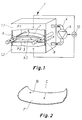
- a furnace 1 is divided with a ceiling 3 into a top furnace section 1.1 and a bottom furnace section 1.2. Between furnace sections or chambers 1.1 and 1.2 extends a conduit or manifold 4, fitted with a fan 5 for carrying air from top furnace section 1.1 to bottom section 1.2.
- the ceiling 3 is provided with an opening 3.1 (see also figs. 3A, 7 and 8), a ring mould 6 and a glass sheet 7 supported thereby being positioned above and in alignment with said opening.
- the rim of opening 3.1 can be more or less sealed against ring mould 6 by means of a collar-shaped gasket 3.2. Partition 3 and collar 3.2 can be made of sheet metal.
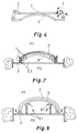
- fig. 3 illustrates a mould assembly for effecting downward bending of the marginal and corner areas of a glass sheet while lifting up the central portion. Lifting up the central portion is thus effected by means of both the mould assembly and said pressure difference.
- Fig. 3A shows a glass sheet 7 atthe initial stage of heating.
- fig. 3B a glass sheet hasalready bent almost to the shape of a mould.
- This flow serves to heat the marginal sections of a glass sheet and contributes to the downward bending thereof.
- the flow in itself does not create in the marginal sections a pressure difference which would exceed that prevailing in the central area.
- a glass sheet can be carried to tempering.
- the glass sheet can be carried into a tempering section 2 as shown e.g. in fig. 5.
- said ceiling 3 is horizontally displaceable and, thus, the pressure difference over glass sheet 7 can be maintained during the transfer of mould 6 from furnace 1 into tempering section 2.
- a valve 4.3 is employed for directing the blast from a conduit leg 4.1 into a conduit leg 4.2 to below an entrance gate 10in order to make sure that the glass-sheet 7 supporting pressure is maintained up to the start of a tempering blast or at least up to the time so close to a tempering blast effect that there is no time for glass sheet 7 to reshape itself through bending or sagging downwards.
- an entrance gate 10 is employed for directing the blast from a conduit leg 4.1 into a conduit leg 4.2 to below an entrance gate 10in order to make sure that the glass-sheet 7 supporting pressure is maintained up to the start of a tempering blast or at least up to the time so close to a tempering blast effect that there is no time for glass sheet 7 to reshape itself through bending or sagging downwards.
- the glass-sheet 7 supporting pressure is maintained up to the start of a tempering blast or at least up to the time so close to a tempering blast effect that there is no time for glass sheet 7 to reshape itself through
- Fig. 4 illustrates a mould including lever linkages 9 which provide mechanical benders for gripping on the edge of glass sheet 7, which turn the edges of a glass sheet downwards even in the case that said pressure difference should prevent downward bending of the edges in a reasonable period of time and at a reasonable tempering temperature.
- said mould 6 is provided with holes or slots 11 for passing air from higher pressure P2 to lower pressure P1 therethrough.
- the disposition and shaping of holes or slots 11 can be used to control this air flow so as to produce a boosted convection effect on critical bending areas.
- the surface area of opening 3.1 and sealing collar 3.2 is considerably smaller than that of ring mould 6, whereby the pressure-difference effect can be focused on the central area of a glass sheet while the downward-bending marginal areas are freely allowed to bend downwards without any resistance on the part of said pressure difference.
- the marginal areas of a glass sheet can be provided even with sharp bends.
- the transfer of glass sheet 7 and mould 6 between a furnace and a tempering section can be effected e.g. by means of shifting rods 8 (fig. 1) to which said mould 6 is attached.
- said fan 5 Since a pressure difference between furnace sections 1.1 and 1.2 is not needed until the time that a glass sheet begins its bending, said fan 5 need not be operated at the early stage of a heating cycle provided that the heating of glass sheet 7 to its final bending temperature is not effected until in bending furnace 1. On the other hand, if a glass sheet 7 heated to a bending temperature or close to a bending temperature is brought into bending section 1 from a preceding furnace section, said fan 5 can be in continuous operation. However, towards the end of a bending procedure, especially if ceiling 3 and collar 3.2 are quite tightly sealed, the blasting power 5 must be lowered in order not to increase the pressure difference between furnace sections 1.1 and 1.2 after said glass sheet 7 has shut off the flow path.
- a method of the invention offers e.g. the following benefits:
Landscapes
- Chemical & Material Sciences (AREA)
- Engineering & Computer Science (AREA)
- Materials Engineering (AREA)
- Organic Chemistry (AREA)
- Mechanical Engineering (AREA)
- Re-Forming, After-Treatment, Cutting And Transporting Of Glass Products (AREA)
Abstract
Claims (12)
- Procédé de bombage d'une feuille de verre (7), le procédé comprenant les étapes suivantes :- la feuille de verre (7) est chauffée dans un four de bombage (1) à proximité de sa température de ramollissement,- la feuille de verre chauffée (7) est supportée par un squelette annulaire (6),- la feuille de verre peut se bomber sous l'action des forces de pesanteur,caractérisé en ce que l'air circule d'une section (1.1) de four au-dessus de la feuille de verre (7) à bomber dans une section de four (1.2) qui se trouve sous la feuille de verre afin qu'un effet de différence de pression soit créé de part et d'autre de la feuille de verre (7), et en ce que cet effet de pression est tel que la feuille de verre bombée est supportée dans sa région centrale qui est chauffée à une température suffisante pour qu'elle subisse un bombage et/ou une trempe, cette température étant suffisamment élevée pour que, en l'absence de l'effet de la pression, la région centrale de la feuille de verre présente une déformation et un affaissement excessifs.
- Procédé selon la revendication 1, caractérisé en ce qu'une partie au moins de l'air qui circule vers la partie qui se trouve sous la feuille de verre (7) est soufflée contre la surface inférieure de la feuille de verre de manière focalisée localement afin que l'effet de chauffage par convection des zones critiques de bombage (B) soit accru.
- Procédé selon la revendication 1 ou 2, caractérisé en ce que, pour que l'effet de pression soit renforcé, le four (1) comporte un plafond (3) ayant une ouverture (3.1) de positionnement du squelette annulaire (6) avec sa feuille de verre (7) dans l'alignement de l'ouverture.
- Procédé selon l'une des revendications 1 à 3, caractérisé en ce que les régions marginales et/ou de coin de la feuille de verre (7) sont bombées par déformation vers le bas avec soulèvement de la région centrale à l'aide de l'effet de pression.
- Procédé selon l'une des revendications 1 à 4, caractérisé en ce que les effets de différence de pression existant de part et d'autre de la feuille de verre (7) sont mesurés et la puissance d'un ventilateur (5) de circulation d'air est ajustée en fonction de cette mesure (12).
- Procédé selon l'une des revendications 1 à 5, caractérisé en ce que le bombage des régions marginales de la feuille de verre (7) est facilité par des éléments mécaniques (9) de pression.
- Procédé selon la revendication 1 ou 3, caractérisé en ce que l'effet de différence de pression est crée entre les surfaces opposées de la feuille de verre (7) même pendant son transport du four (1) à une section de trempe (2).
- Appareil de bombage d'une feuille de verre (7), l'appareil comprenant :- un four (1) de bombage ayant des dispositifs de chauffage destinés à maintenir la température du four à une valeur suffisamment élevée pour le bombage de la feuille de verre, et- un squelette annulaire (6) destiné à porter la feuille de verre (7) à bomber dans le four de bombage,
caractérisé en ce que l'appareil comporte en outre :- un plafond (3) qui divise le four en une section supérieure et une section inférieure (1.1 et 1.2), le plafond (3) ayant une ouverture (3.1) qui est alignée sur la région centrale ouverte du squelette annulaire (6),- un conduit ou collecteur (4) destiné à raccorder la section de four (1.1) qui se trouve au-dessus du plafond (3) à la section de four (1.2) qui se trouve au-dessous du plafond, et- un ensemble de soufflage (5) destiné à transporter l'air dans le conduit ou collecteur de la section supérieure (1.1) à la section inférieure (1.2), un effet de différence de pression étant produit aux faces opposées de la feuille de verre (7) afin que la feuille de verre soit supportée par-dessous. - Appareil selon la revendication 8, caractérisé en ce que le rebord de l'ouverture (3.1) formé dans le plafond (3) coopère de façon étanche (3.2) au moins partiellement avec le squelette annulaire (6).
- Appareil selon l'une des revendications 8 et 9, caractérisé en ce que le squelette annulaire (6) a des trous (11) ou fentes de circulation d'un courant d'air de la section inférieure (1.1) à la section supérieure (1.2) du four.
- Appareil selon l'une des revendications 8 à 10, caractérisé en ce que l'ouverture (3.1) formée dans le plafond (3) délimite une surface inférieure au rebord du squelette annulaire (6), si bien qu'une partie seulement de la surface inférieure de la feuille de verre (7) est soumise à un effet de pression accrue (P₂).
- Appareil selon la revendication 8, caractérisé en ce que le plafond (3) est mobile horizontalement ou verticalement.
Applications Claiming Priority (3)
| Application Number | Priority Date | Filing Date | Title |
|---|---|---|---|
| FI903397A FI86054C (fi) | 1990-07-05 | 1990-07-05 | Foerfarande och anordning foer boejning av glasskiva. |
| FI903397 | 1990-07-05 | ||
| PCT/FI1991/000187 WO1992000921A1 (fr) | 1990-07-05 | 1991-06-12 | Procede et dispositif de cintrage d'une plaque de verre |
Publications (2)
| Publication Number | Publication Date |
|---|---|
| EP0537182A1 EP0537182A1 (fr) | 1993-04-21 |
| EP0537182B1 true EP0537182B1 (fr) | 1995-02-01 |
Family
ID=8530754
Family Applications (1)
| Application Number | Title | Priority Date | Filing Date |
|---|---|---|---|
| EP91910483A Expired - Lifetime EP0537182B1 (fr) | 1990-07-05 | 1991-06-12 | Procede et dispositif de cintrage d'une plaque de verre |
Country Status (6)
| Country | Link |
|---|---|
| US (1) | US5292355A (fr) |
| EP (1) | EP0537182B1 (fr) |
| CN (1) | CN1057820A (fr) |
| DE (1) | DE69107210T2 (fr) |
| FI (1) | FI86054C (fr) |
| WO (1) | WO1992000921A1 (fr) |
Cited By (1)
| Publication number | Priority date | Publication date | Assignee | Title |
|---|---|---|---|---|
| US5893941A (en) * | 1994-10-25 | 1999-04-13 | Nikander; Risto | Method and apparatus in bending and tempering of a glass sheet |
Families Citing this family (15)
| Publication number | Priority date | Publication date | Assignee | Title |
|---|---|---|---|---|
| US5669952A (en) * | 1994-10-14 | 1997-09-23 | Ppg Industries, Inc. | Pressure forming of glass sheets |
| US5907770A (en) * | 1995-07-19 | 1999-05-25 | Semiconductor Energy Laboratory Co., | Method for producing semiconductor device |
| US6902616B1 (en) * | 1995-07-19 | 2005-06-07 | Semiconductor Energy Laboratory Co., Ltd. | Method and apparatus for producing semiconductor device |
| FI100397B (fi) * | 1995-10-24 | 1997-11-28 | Glassrobots Oy | Lämmönsiirtomenetelmä lasilevyjen taivutusuunissa ja taivutusuuni |
| TW558861B (en) * | 2001-06-15 | 2003-10-21 | Semiconductor Energy Lab | Laser irradiation stage, laser irradiation optical system, laser irradiation apparatus, laser irradiation method, and method of manufacturing semiconductor device |
| JP2003160346A (ja) * | 2001-11-22 | 2003-06-03 | Murakami Corp | ガラス基板の曲面成形方法 |
| JP2004131347A (ja) * | 2002-10-11 | 2004-04-30 | Asahi Glass Co Ltd | ガラス板の曲げ成形方法 |
| DE10314266B3 (de) * | 2003-03-29 | 2004-06-09 | Saint-Gobain Sekurit Deutschland Gmbh & Co. Kg | Verfahren und Vorrichtung zum Biegen von Glasscheiben |
| US20050092026A1 (en) * | 2003-11-03 | 2005-05-05 | Merola Janice E. | Curved support fixtures for shape control |
| GB0604459D0 (en) * | 2006-03-06 | 2006-04-12 | Gramplan Health Board | Needle guidance apparatus |
| CN101337764B (zh) * | 2008-06-10 | 2011-01-05 | 黄世荣 | 用于生产拱形玻璃的模具及用该模具生产拱形玻璃的方法 |
| US20110247367A1 (en) * | 2010-04-08 | 2011-10-13 | Glasstech, Inc. | Press bending station and method for bending heated glass sheets |
| WO2017029252A1 (fr) * | 2015-08-18 | 2017-02-23 | Saint-Gobain Glass France | Dispositif et procédé de cintrage de verre au moyen d'un ventilateur |
| KR102368787B1 (ko) | 2015-10-08 | 2022-03-03 | 삼성디스플레이 주식회사 | 열성형 방법 및 열성형 장치 |
| CN107473576B (zh) * | 2017-09-22 | 2020-05-22 | 张家界永兴玻璃有限公司 | 一种玻璃加工装置 |
Family Cites Families (7)
| Publication number | Priority date | Publication date | Assignee | Title |
|---|---|---|---|---|
| US3431095A (en) * | 1965-11-24 | 1969-03-04 | Libbey Owens Ford Glass Co | Glass bending furnace |
| GB1190371A (en) * | 1966-04-25 | 1970-05-06 | Pilkington Brothers Ltd | Improvements in or relating to the Bending of Glass Sheets |
| US4119424A (en) * | 1977-06-03 | 1978-10-10 | Ppg Industries, Inc. | Method and apparatus for shaping glass sheets on a bending mold |
| US4300935A (en) * | 1979-06-01 | 1981-11-17 | Ppg Industries, Inc. | Shaping glass sheets by drop forming with improved sag control |
| US4356018A (en) * | 1981-09-04 | 1982-10-26 | Mcmaster Harold | Method and apparatus for deep bending glass sheets |
| GB8604246D0 (en) * | 1986-02-20 | 1986-03-26 | Pilkington Brothers Plc | Manufacture of curved glass |
| FI81331C (fi) * | 1988-11-24 | 1990-10-10 | Tamglass Oy | Vaermeoeverfoeringsfoerfarande i en boejningsugn foer glasskivor och en boejningsugn. |
-
1990
- 1990-07-05 FI FI903397A patent/FI86054C/fi active IP Right Grant
-
1991
- 1991-06-12 WO PCT/FI1991/000187 patent/WO1992000921A1/fr not_active Ceased
- 1991-06-12 US US07/956,481 patent/US5292355A/en not_active Expired - Lifetime
- 1991-06-12 EP EP91910483A patent/EP0537182B1/fr not_active Expired - Lifetime
- 1991-06-12 DE DE69107210T patent/DE69107210T2/de not_active Expired - Fee Related
- 1991-07-05 CN CN91104580.5A patent/CN1057820A/zh active Pending
Cited By (1)
| Publication number | Priority date | Publication date | Assignee | Title |
|---|---|---|---|---|
| US5893941A (en) * | 1994-10-25 | 1999-04-13 | Nikander; Risto | Method and apparatus in bending and tempering of a glass sheet |
Also Published As
| Publication number | Publication date |
|---|---|
| CN1057820A (zh) | 1992-01-15 |
| WO1992000921A1 (fr) | 1992-01-23 |
| FI903397A0 (fi) | 1990-07-05 |
| FI86054B (fi) | 1992-03-31 |
| FI903397A7 (fi) | 1992-01-06 |
| FI86054C (fi) | 1992-07-10 |
| DE69107210T2 (de) | 1995-05-24 |
| EP0537182A1 (fr) | 1993-04-21 |
| DE69107210D1 (de) | 1995-03-16 |
| US5292355A (en) | 1994-03-08 |
Similar Documents
| Publication | Publication Date | Title |
|---|---|---|
| EP0537182B1 (fr) | Procede et dispositif de cintrage d'une plaque de verre | |
| EP0592862B1 (fr) | Procédé et four de bombage des feuilles de verre | |
| US4297118A (en) | Controlling overheating of vacuum mold used to shape glass sheets | |
| KR940011121B1 (ko) | 유리판 굽힘 방법 및 장치 | |
| US3468645A (en) | Method and apparatus for shaping glass sheets supported on a gas support bed | |
| US4349375A (en) | Deformable vacuum mold for shaping glass sheets | |
| EP0121258A2 (fr) | Façonnage de formes complexes avec des feuilles de verre | |
| US5306324A (en) | Method and apparatus for bending and tempering a glass sheet | |
| US4285715A (en) | Cycle of mold movement while press bending glass sheets | |
| US5318615A (en) | Method of and apparatus for forming bent sheet glass | |
| CA1152327A (fr) | Appareil pour le formage des feuilles de verre au moyen d'un moule diformable, a depression, et methode connexe | |
| CA1120725A (fr) | Appareillage de pliage et de recuit du verre | |
| US5259859A (en) | Lightweight vacuum shuttle | |
| JP3771278B2 (ja) | 板ガラスの湾曲成形方法及び装置 | |
| US4356018A (en) | Method and apparatus for deep bending glass sheets | |
| US4252552A (en) | Shaping glass sheets using molds of different shapes | |
| CA1241198A (fr) | Moule sous vide pour la mise en forme de feuilles de verre | |
| WO1996012682A1 (fr) | Procede permettant de cintrer et de tremper une feuille de verre et appareillage correspondant | |
| AU2004226204A1 (en) | Method and device for crowning glass sheets | |
| CA1283294C (fr) | Moule-presse a surface developpee | |
| US5022906A (en) | Process for obtaining bent-tempered motor vehicle glazings | |
| JPS59232926A (ja) | 真空ホルダ | |
| WO1993006052A1 (fr) | Procede de cintrage et de trempe de feuilles de verre | |
| US4272275A (en) | Aligning glass sheets on an outline mold prior to transfer to shaping mold | |
| US4119426A (en) | Method and apparatus for eliminating tong vents in a glass sheet furnace |
Legal Events
| Date | Code | Title | Description |
|---|---|---|---|
| PUAI | Public reference made under article 153(3) epc to a published international application that has entered the european phase |
Free format text: ORIGINAL CODE: 0009012 |
|
| 17P | Request for examination filed |
Effective date: 19921222 |
|
| AK | Designated contracting states |
Kind code of ref document: A1 Designated state(s): CH DE FR IT LI |
|
| RAP1 | Party data changed (applicant data changed or rights of an application transferred) |
Owner name: NIKANDER, RISTO KALEVI |
|
| RIN1 | Information on inventor provided before grant (corrected) |
Inventor name: NIKANDER, RISTO KALEVI |
|
| 17Q | First examination report despatched |
Effective date: 19940603 |
|
| ITF | It: translation for a ep patent filed | ||
| GRAA | (expected) grant |
Free format text: ORIGINAL CODE: 0009210 |
|
| AK | Designated contracting states |
Kind code of ref document: B1 Designated state(s): CH DE FR IT LI |
|
| REF | Corresponds to: |
Ref document number: 69107210 Country of ref document: DE Date of ref document: 19950316 |
|
| ET | Fr: translation filed | ||
| PLBE | No opposition filed within time limit |
Free format text: ORIGINAL CODE: 0009261 |
|
| STAA | Information on the status of an ep patent application or granted ep patent |
Free format text: STATUS: NO OPPOSITION FILED WITHIN TIME LIMIT |
|
| 26N | No opposition filed | ||
| PGFP | Annual fee paid to national office [announced via postgrant information from national office to epo] |
Ref country code: CH Payment date: 20020625 Year of fee payment: 12 |
|
| PG25 | Lapsed in a contracting state [announced via postgrant information from national office to epo] |
Ref country code: CH Free format text: LAPSE BECAUSE OF NON-PAYMENT OF DUE FEES Effective date: 20030630 Ref country code: LI Free format text: LAPSE BECAUSE OF NON-PAYMENT OF DUE FEES Effective date: 20030630 |
|
| PGFP | Annual fee paid to national office [announced via postgrant information from national office to epo] |
Ref country code: FR Payment date: 20031204 Year of fee payment: 13 |
|
| PGFP | Annual fee paid to national office [announced via postgrant information from national office to epo] |
Ref country code: DE Payment date: 20031223 Year of fee payment: 13 |
|
| REG | Reference to a national code |
Ref country code: CH Ref legal event code: PL |
|
| PG25 | Lapsed in a contracting state [announced via postgrant information from national office to epo] |
Ref country code: DE Free format text: LAPSE BECAUSE OF NON-PAYMENT OF DUE FEES Effective date: 20050101 |
|
| PG25 | Lapsed in a contracting state [announced via postgrant information from national office to epo] |
Ref country code: FR Free format text: LAPSE BECAUSE OF NON-PAYMENT OF DUE FEES Effective date: 20050228 |
|
| REG | Reference to a national code |
Ref country code: FR Ref legal event code: ST |
|
| PGFP | Annual fee paid to national office [announced via postgrant information from national office to epo] |
Ref country code: IT Payment date: 20060630 Year of fee payment: 16 |
|
| PG25 | Lapsed in a contracting state [announced via postgrant information from national office to epo] |
Ref country code: IT Free format text: LAPSE BECAUSE OF NON-PAYMENT OF DUE FEES Effective date: 20070612 |