EP0537261B1 - Structures incorporant des pneus de vehicules usages - Google Patents
Structures incorporant des pneus de vehicules usages Download PDFInfo
- Publication number
- EP0537261B1 EP0537261B1 EP19910912805 EP91912805A EP0537261B1 EP 0537261 B1 EP0537261 B1 EP 0537261B1 EP 19910912805 EP19910912805 EP 19910912805 EP 91912805 A EP91912805 A EP 91912805A EP 0537261 B1 EP0537261 B1 EP 0537261B1
- Authority
- EP
- European Patent Office
- Prior art keywords
- tyres
- row
- piles
- fastened together
- wall
- Prior art date
- Legal status (The legal status is an assumption and is not a legal conclusion. Google has not performed a legal analysis and makes no representation as to the accuracy of the status listed.)
- Expired - Lifetime
Links
Images


Classifications
-
- E—FIXED CONSTRUCTIONS
- E02—HYDRAULIC ENGINEERING; FOUNDATIONS; SOIL SHIFTING
- E02B—HYDRAULIC ENGINEERING
- E02B3/00—Engineering works in connection with control or use of streams, rivers, coasts, or other marine sites; Sealings or joints for engineering works in general
- E02B3/04—Structures or apparatus for, or methods of, protecting banks, coasts, or harbours
- E02B3/12—Revetment of banks, dams, watercourses, or the like, e.g. the sea-floor
- E02B3/122—Flexible prefabricated covering elements, e.g. mats, strips
- E02B3/126—Flexible prefabricated covering elements, e.g. mats, strips mainly consisting of bituminous material or synthetic resins
-
- E—FIXED CONSTRUCTIONS
- E02—HYDRAULIC ENGINEERING; FOUNDATIONS; SOIL SHIFTING
- E02B—HYDRAULIC ENGINEERING
- E02B2201/00—Devices, constructional details or methods of hydraulic engineering not otherwise provided for
- E02B2201/04—Devices, constructional details or methods of hydraulic engineering not otherwise provided for using old tires for hydraulic engineering
-
- Y—GENERAL TAGGING OF NEW TECHNOLOGICAL DEVELOPMENTS; GENERAL TAGGING OF CROSS-SECTIONAL TECHNOLOGIES SPANNING OVER SEVERAL SECTIONS OF THE IPC; TECHNICAL SUBJECTS COVERED BY FORMER USPC CROSS-REFERENCE ART COLLECTIONS [XRACs] AND DIGESTS
- Y02—TECHNOLOGIES OR APPLICATIONS FOR MITIGATION OR ADAPTATION AGAINST CLIMATE CHANGE
- Y02A—TECHNOLOGIES FOR ADAPTATION TO CLIMATE CHANGE
- Y02A10/00—TECHNOLOGIES FOR ADAPTATION TO CLIMATE CHANGE at coastal zones; at river basins
- Y02A10/30—Flood prevention; Flood or storm water management, e.g. using flood barriers
-
- Y—GENERAL TAGGING OF NEW TECHNOLOGICAL DEVELOPMENTS; GENERAL TAGGING OF CROSS-SECTIONAL TECHNOLOGIES SPANNING OVER SEVERAL SECTIONS OF THE IPC; TECHNICAL SUBJECTS COVERED BY FORMER USPC CROSS-REFERENCE ART COLLECTIONS [XRACs] AND DIGESTS
- Y02—TECHNOLOGIES OR APPLICATIONS FOR MITIGATION OR ADAPTATION AGAINST CLIMATE CHANGE
- Y02W—CLIMATE CHANGE MITIGATION TECHNOLOGIES RELATED TO WASTEWATER TREATMENT OR WASTE MANAGEMENT
- Y02W30/00—Technologies for solid waste management
- Y02W30/50—Reuse, recycling or recovery technologies
- Y02W30/62—Plastics recycling; Rubber recycling
Definitions
- This invention relates to structures incorporating used vehicle tyres.
- Examples of such structures are sea defence systems for defending a coastline against erosion by the sea, and retaining walls such as are used for retaining river walls or for retaining earth walls.
- Document SU-A-1 476 041 discloses a barrier structure with a body composed of tyres arranged side-by-side with their planes vertical. The tyres are connected to each other and to adjacent rows of side-by side tyres by junction elements.
- Document DE-A-25 14 830 discloses structures which use old vehicle tyres in various configurations.
- tyres are arranged in piles and are each joined to the adjacent tyre in the pile by metal clamps, by U-shaped tyre bead shoes, by adhesive or by placing wires or rods through the tyre side walls.
- Tyres mounted together in this way are used as tubes, ie the inner passage of the tyres is used as a conduit.
- This document also discloses an arrangement of tyres in one plane with tyres linked to one another to form a linear chain or a two-dimensional net.
- a structure comprising interlinked used vehicle tyres, the tyres being fastened together in piles with the tyres in each pile being arranged coaxially, characterised in that piles of tyres are fastened together in at least one row, with all the tyres being fastened together by cables which pass through the central apertures of adjacent tyres, thus allowing a degree of flexibility between the tyres so that the tyres can move to a sufficient extent for them to conform to local conditions.
- references in this specification to 'cables' includes all equivalent types of fasteners, for example ropes, chains, wire cables, straps or webbing.
- cables allows a degree of flexibility between the tyres so that the tyres can move to a sufficient extent for them to conform to local conditions, either on a coastline or in a retaining wall.
- chains are used, the advantage is obtained that tyres can be simply added to or removed from the structure by undoing chain fasteners, or connecting further lengths of chain to the links.
- chains it is possible to use other types of flexible fasteners, for example ropes or webbing. It is particularly advantageous to use a material which is similar in its wear resistance and flexibility to the material of the tyres themselves.
- the structure may be made up by fastening together three piles to form a building unit, and then building the structure with such units. At least the bottom tyres in each pile may be buried in the ground.
- the invention may be used as a sea defence system comprising a structure as set forth above, wherein the row or rows of tyre piles extend parallel to a coastline and the tyres are fastened together so that a force impacting at a point along the tyre row(s) is resisted by a tension along the length of the row. At least the ends of the row are preferably anchored to the ground.
- An anti-scour mat made up of a plurality of interlinked tyres, which all lie in the same plane, may be connected to the bottom of the row of tyres.
- One or more piers constructed of piles of tyres, may be provided. These piers can extend one one side of the row of tyres. Posts may be driven through the centre of some or all of the piles of tyres forming the piers.
- a protective wall may be attached to the row of tyres on the side facing the sea.
- the invention may also be embodied in a river wall defence system comprising a structure as set forth above, wherein the row or rows of tyre piles extend parallel to the river bank and the tyres are fastened together and form an elongate barrier along the river bank.
- the invention may be embodied in a wall retention system comprising a structure as set forth above, wherein the row or rows of tyre piles extend parallel to the line of the wall, the tyres are fastened together andform an elongate barrier along the line of the wall.
- the tyres are laid in piles with one tyre being laid directly on top of another so that when the pile is complete, the central apertures of all the tyres register with one another and the central void of all the tyres can be filled with filling material through the top of the pile.
- Used vehicle tyres have the great advantage that they are readily available and can be acquired at little or no cost. They are very resistant to corrosion and degradation in the aggressive atmosphere on the sea coast. Because they are flexible they can absorb some of the force from the sea by the yielding of individual tyres against that force, whilst the wall of tyres holds firm to resist the force.
- the tyres may be painted to blend in with their surroundings, and techniques for painting tyres are known.
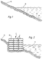
- Figure 1 shows a shelving coastline at 10, with the sea shown at 12. The high water level is indicated at 14, and the low water level by a dotted line at 16.
- piles 2 of used vehicle tyres 4 are arranged as shown in the Figures.
- the tyres 4 are piled one on top of another, and the piles are then placed in rows 7 to form a wall which extends parallel to the shore (see for example Figure 4).
- Most importantly however all the tyres 4 are linked to one another so that each tyre is held in place by its neighbours and by the tyres above and below it (see Figure 10).
- the tyres are linked to one another by chains 6 which are pulled as tight as possible in order to secure the tyres and to reduce the amount which they are able to move.
- the chains have been omitted from the drawing, but in practice each tyre will be secured to its neighbours immediately above and below as well as on either side and behind.
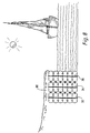
- the inland piles of tyres may be completely buried under the beach material, or they may be exposed as shown in Figure 2.
- Figure 3 shows three rows of tyres 40, 42, 44 all linked together by chains as previously described.
- concrete anchor blocks 46 are embedded in the shore, and the body of tyres is connected to these blocks by chains 48.
- anchor points 50 made up of further sets of tyres are embedded in the shore inland of the rows of tyres, and the main tyre bodies are connected to these anchor points by further chains 52.
- an anti-scour mat 54 can be used.
- the tyres in the mat may be filled with concrete so that they present a substantially continuous surface against the action of the sea.
- the tyres will be linked together to form a mat or apron which will initially be embedded in the shore a small distance below the shore surface, and connected to the bottom of the row 44 of tyres. If scour continues to occur, the mat will move as the shore profile moves to the positions indicated in dotted lines, but will play a substantial role in reducing the action of scour in undermining the wall formed by the rows of tyres.
- FIG 4 it will be seen how the tyres can be arranged in a hexagonal array in front of and behind the row 7, with all the tyres being interconnected by chains 6.
- the wall may be one row deep or more. It is however important that all the tyres in the front row should be linked to one another along the length of the coastline so that when a wave breaks on the wall and tries to push the tyres out of line, then this force will be resisted by a tension in the front row.
- Figure 5 also shows the construction of a breakwater 24 formed by linking together piles of tyres so that they extend out into the sea.
- This breakwater will be effective in a known manner to prevent or to reduce the effect of a wave crest travelling along the length of the coastline and carrying material from the coastline with it as it goes.
- the tyre piles will drop down to fill any void left as a result of the action of scour, and if necessary, some of the chains 6 can be released to allow certain of the tyres to drop down into a void beneath.
- a concealing wall 26 as shown in Figure 6 to hide the tyres 4 from view.
- the wall 26 will just be cosmetic in nature, and the strength of the sea defence system will be provided by the piles of tyres.
- the wall 26 can be built for example of concrete and may be secured to the wall by chains 28.
- a quay or breakwater 60 is formed by interlinked tyres which are attached to a sea defence construction 62 on the land.
- the breakwater 60 is formed by wooden posts 64 which are driven into the sea bed and then have one or more tyres 66 dropped over the post, with all the tyres being linked to one another in the manner already described.
- the presence of the posts helps to locate the arrangement of interlinked tyres in the sea 68, and the tyres and the interlinking structure means that the demands on the posts themselves will be less than in a conventional breakwater and the posts can therefore be of a smaller dimension than might otherwise be expected.
- Figure 8 shows a scheme for bank retention on a river wall.
- the arrangement of tyres is similar to that described with reference to Figure 2. It will be seen that the natural bank material is extended at 30 to cover the three rows of tyres 32, 34, 36. In this way the tyres are substantially hidden from view.
- FIG. 9 shows a cross section through a bank 110 above a road 112.
- the bank has been stabilised by embedding tyres 115 within the bank, at the level of the roadway 112.
- the tyres form three parallel rows 114, 116, 118, each of which extend parallel to the surface of the bank 110 and all of which are linked to one another.
- the most important linkage is that parallel to the length of the bank 110, but the tyres are also linked to the adjacent tyres above and below and to the tyres in front and behind.
- the tyres are completely buried in the bank 110 and are not visible.
- the central apertures of the tyres will be filled with local ballast material typically in the form of soil from the site. The presence of the tyres in this position will stabilise and retain the bank 110.
- the invention thus provides a support structure which can be constructed with a minimum of cost, and without any specialised equipment.
- the piles of tyres will bed themselves into the coastline and will have sufficient resilience to absorb some of the force of the sea whilst the linking together of the tyres will provide sufficient strength to resist erosion.
- the invention however also contemplates the use of interlinked motor vehicle tyres to support and strengthen a number of engineering structures both at the interface between land and sea, and entirely on the land.
- interlinking the tyres as described, and filling them with ballast material as available on site a stable structure is achieved which can be built at low cast because tyres are available readily, and without any particular degree of skill because all that is required is that the tyres be linked to one another as shown.
Landscapes
- Engineering & Computer Science (AREA)
- General Engineering & Computer Science (AREA)
- Environmental & Geological Engineering (AREA)
- Ocean & Marine Engineering (AREA)
- Mechanical Engineering (AREA)
- Civil Engineering (AREA)
- Structural Engineering (AREA)
- Revetment (AREA)
- Separation, Recovery Or Treatment Of Waste Materials Containing Plastics (AREA)
- Compositions Of Macromolecular Compounds (AREA)
Abstract
Claims (11)
- Une structure comprenant des pneus de véhicules usagés liés entre eux, les pneus (4) étant attachés ensembles et empilés les uns sur les autres (2), les pneus étant disposés de façon coaxialle dans chaque pile, caractériseé par le fait que des piles de pneus sont attachées ensembles de façon à former au moins une rangée (7), les pneus étant attachés ensembles par des cables (6) passant par l'ouverture centrale des pneus adjacents, la structure disposant ainsi d'une certaine flexibilité permettant aux pneus de bouger suffisament afin de pouvoir s'adapter aux conditions locales.
- Une structure selon la revendication 1, ou trois piles (2) sont attachées ensembles de façon à former une unité de construction, la structure étant formée de telles unités.
- Une structure selon l'une des revendications précédentes où moins les pneus de dessous de chaque pile sont enterrés dans le sol.
- Une structure selon la revendication 1, étant utilisée dans un système de défense contre la mer, où la/les rangée(s) (7) de piles de pneus (2) longe(nt) parallèlement la côte et où les pneus sont attachès ensembles de telle façon que, dans le cas où une partie de la/les rangée(s) de pneus reçoit un fort impact, il est possible de résister à ce fort impact grâce à une tension s'exerçant tout au long de la rangée.
- Un système de défense contre la mer selon la revendication 4, où les extrémités de la rangée (7) sont enfouis dans le sol.
- Un système de défense contre la mer selon l'une des revendications de 4 à 5, où un tapis anti-frottant (54) composé de plusieurs pneus liés entre eux, tous à plât au même niveau, est rattaché au dessous de la rangée (44) de pneus.
- Un système de défense contre la mer selon l'une des revendications de 4 à 6, comprenant une ou plusiers jetée(s) (24), construites à partir de piles de pneus, lesquelles jetées s'étendent sur un côté de la de la rangée (7) de pneus.
- Un système de défense contre la mer selon la revendication 7, où des poteaux sont plantés au centre de certaines ou de toutes les piles de pneus (66) formant les jetées.
- Un système de défense contre la mer selon l'une des revendications de 4 à 8, où un mur protecteur (26) est rattaché à la rangée de pneus du côté donnant sur la mer (12).
- Une structure selon la revendication 1, servant de système de protection des berges d'une rivière, où la/les rangée(s) (32, 34, 36) de piles de pneus sont disposée(s) de parallèlement aux berges de la rivière (30) et où les pneus sont attachés ensembles et formant une barrière s'étendant tout au long des berges.
- Une structure selon la revendication 1, étant utilisée dans un système de maintien des berges d'une rivière, où la/les rangée(s) (114, 116, 118) de piles de pneus est/sont disposée(s) parallèlement au mur (110), les pneus étant attachés ensembles et formant une barrière s'étendant tout au long du mur.
Applications Claiming Priority (5)
| Application Number | Priority Date | Filing Date | Title |
|---|---|---|---|
| GB9014905 | 1990-07-05 | ||
| GB909014905A GB9014905D0 (en) | 1990-07-05 | 1990-07-05 | Sea defences |
| GB9017292 | 1990-08-07 | ||
| GB909017292A GB9017292D0 (en) | 1990-08-07 | 1990-08-07 | Wall retention |
| PCT/GB1991/001085 WO1992001118A1 (fr) | 1990-07-05 | 1991-07-03 | Structures incorporant des pneus de vehicules usages |
Publications (2)
| Publication Number | Publication Date |
|---|---|
| EP0537261A1 EP0537261A1 (fr) | 1993-04-21 |
| EP0537261B1 true EP0537261B1 (fr) | 1996-03-20 |
Family
ID=26297280
Family Applications (1)
| Application Number | Title | Priority Date | Filing Date |
|---|---|---|---|
| EP19910912805 Expired - Lifetime EP0537261B1 (fr) | 1990-07-05 | 1991-07-03 | Structures incorporant des pneus de vehicules usages |
Country Status (4)
| Country | Link |
|---|---|
| EP (1) | EP0537261B1 (fr) |
| AU (1) | AU643055B2 (fr) |
| DE (1) | DE69118186D1 (fr) |
| WO (1) | WO1992001118A1 (fr) |
Families Citing this family (8)
| Publication number | Priority date | Publication date | Assignee | Title |
|---|---|---|---|---|
| GB2267724A (en) * | 1992-06-09 | 1993-12-15 | Ronald Ernest Southey | Structures incorporating used vehicle tyres |
| WO1999014440A1 (fr) * | 1997-09-13 | 1999-03-25 | Thomas Gabor | Procede pour la consolidation, la stabilisation ainsi que la recuperation de surfaces de sol et de terrains de fondation sur et sous l'eau |
| FR2772230B1 (fr) * | 1997-12-15 | 2003-09-19 | Saint Leger Xavier De | Dispositif de protection des terres contre les nuisibles notamment les ragondins |
| GB2368363B (en) * | 2000-10-27 | 2005-03-16 | Anthony Robinson | Method of disposing of used vehicle tyres |
| US20070289657A1 (en) * | 2004-12-24 | 2007-12-20 | Gunson Robert J | Tyre Placement and Pilling Apparatus and Method |
| CN102286961B (zh) * | 2011-07-11 | 2013-06-12 | 合肥工业大学 | 废轮胎溢流坝 |
| CA2763877A1 (fr) | 2012-01-11 | 2013-07-11 | Douglas Goei | Methode de construction d'une structure de soutien en environnement marin a partir de pneus uses |
| CN115162261B (zh) * | 2022-06-24 | 2023-07-25 | 杭州科技职业技术学院 | 海岸线防护结构及其施工方法 |
Family Cites Families (5)
| Publication number | Priority date | Publication date | Assignee | Title |
|---|---|---|---|---|
| US3842606A (en) * | 1969-02-04 | 1974-10-22 | G Dunan | Beach-protectors |
| DE2324214A1 (de) * | 1973-05-12 | 1974-11-21 | Continental Gummi Werke Ag | Ufer- oder kuestenschutzeinrichtung aus kraftfahrzeugreifen |
| DE2514830A1 (de) * | 1975-04-04 | 1976-10-14 | Hans Friedrich Eberwein | Verfahren zur verwertung von gebrauchten fahrzeugreifen und nach diesem verfahren hergestellte gegenstaende |
| AT368222B (de) * | 1980-06-13 | 1982-09-27 | Gloessl Johann | Gewaesserverbau |
| FR2643400A1 (fr) * | 1989-02-22 | 1990-08-24 | Chevalier Expl Ets | Procede de stabilisation superficielle des sols ou des ouvrages soumis a l'erosion hydraulique |
-
1991
- 1991-07-03 WO PCT/GB1991/001085 patent/WO1992001118A1/fr not_active Ceased
- 1991-07-03 AU AU82024/91A patent/AU643055B2/en not_active Ceased
- 1991-07-03 DE DE69118186T patent/DE69118186D1/de not_active Expired - Lifetime
- 1991-07-03 EP EP19910912805 patent/EP0537261B1/fr not_active Expired - Lifetime
Also Published As
| Publication number | Publication date |
|---|---|
| DE69118186D1 (de) | 1996-04-25 |
| AU643055B2 (en) | 1993-11-04 |
| EP0537261A1 (fr) | 1993-04-21 |
| AU8202491A (en) | 1992-02-04 |
| WO1992001118A1 (fr) | 1992-01-23 |
Similar Documents
| Publication | Publication Date | Title |
|---|---|---|
| US5697736A (en) | Seawalls and shoreline reinforcement systems | |
| US4655637A (en) | Revetment system for preventing bluff erosion | |
| US6893193B2 (en) | Self-anchoring fiber block system | |
| US5641244A (en) | Revetment, revetment system and method for the banks of waterways | |
| AU751554B2 (en) | Woven wire netting for protection against rock falls or for securing a top layer of soil, and method and device for producing same | |
| US6027285A (en) | Mat installation | |
| US5370475A (en) | Erosion barrier system made from tires | |
| US20230002988A1 (en) | Erosion control apparatus | |
| EP0937823B1 (fr) | Procede permettant de lutter contre l'erosion par construction d'un revetement et procede de construction servant a empecher les glissements de terrain | |
| US20110236132A1 (en) | Erosion Control Barrier | |
| EP0537261B1 (fr) | Structures incorporant des pneus de vehicules usages | |
| US20250382761A1 (en) | Erosion control apparatus | |
| US6830411B1 (en) | Artificial island and method of construction thereof | |
| US5499891A (en) | Earth-retaining module and system | |
| JP3608773B2 (ja) | 流下物捕捉構造 | |
| CN1211538C (zh) | 用于水土流失控制和岸防工事的方法以及用于水土流失控制和岸防的结构 | |
| HUP0003696A2 (hu) | Eljárás és berendezés gumiabroncsok feldolgozásához | |
| RU2212497C2 (ru) | Фашинное ячеистое крепление | |
| US5645371A (en) | Bulkhead system | |
| DE2062477A1 (de) | Verfahren und Einrichtung zum Schützen und/oder Stabilisieren von geneigten Fla chen | |
| KR101114521B1 (ko) | 호안 보호 블록 지지용 기초블록 및 이의 시공방법 | |
| RU93001357A (ru) | Берегозащитное сооружение | |
| US5104258A (en) | Bionic dunes | |
| KR20030011206A (ko) | 강재 전면틀과 지오그리드 보강재를 사용한 보강토 옹벽 | |
| KR20100138705A (ko) | 호안블록 지지용 기초블록 |
Legal Events
| Date | Code | Title | Description |
|---|---|---|---|
| PUAI | Public reference made under article 153(3) epc to a published international application that has entered the european phase |
Free format text: ORIGINAL CODE: 0009012 |
|
| 17P | Request for examination filed |
Effective date: 19930114 |
|
| AK | Designated contracting states |
Kind code of ref document: A1 Designated state(s): BE DE ES FR GB IT NL |
|
| 17Q | First examination report despatched |
Effective date: 19940128 |
|
| GRAH | Despatch of communication of intention to grant a patent |
Free format text: ORIGINAL CODE: EPIDOS IGRA |
|
| GRAA | (expected) grant |
Free format text: ORIGINAL CODE: 0009210 |
|
| AK | Designated contracting states |
Kind code of ref document: B1 Designated state(s): BE DE ES FR GB IT NL |
|
| PG25 | Lapsed in a contracting state [announced via postgrant information from national office to epo] |
Ref country code: FR Effective date: 19960320 Ref country code: ES Free format text: THE PATENT HAS BEEN ANNULLED BY A DECISION OF A NATIONAL AUTHORITY Effective date: 19960320 Ref country code: IT Free format text: LAPSE BECAUSE OF FAILURE TO SUBMIT A TRANSLATION OF THE DESCRIPTION OR TO PAY THE FEE WITHIN THE PRESCRIBED TIME-LIMIT;WARNING: LAPSES OF ITALIAN PATENTS WITH EFFECTIVE DATE BEFORE 2007 MAY HAVE OCCURRED AT ANY TIME BEFORE 2007. THE CORRECT EFFECTIVE DATE MAY BE DIFFERENT FROM THE ONE RECORDED. Effective date: 19960320 |
|
| REF | Corresponds to: |
Ref document number: 69118186 Country of ref document: DE Date of ref document: 19960425 |
|
| PG25 | Lapsed in a contracting state [announced via postgrant information from national office to epo] |
Ref country code: DE Effective date: 19960621 |
|
| EN | Fr: translation not filed | ||
| PLBE | No opposition filed within time limit |
Free format text: ORIGINAL CODE: 0009261 |
|
| STAA | Information on the status of an ep patent application or granted ep patent |
Free format text: STATUS: NO OPPOSITION FILED WITHIN TIME LIMIT |
|
| 26N | No opposition filed | ||
| PGFP | Annual fee paid to national office [announced via postgrant information from national office to epo] |
Ref country code: NL Payment date: 19990730 Year of fee payment: 9 |
|
| PGFP | Annual fee paid to national office [announced via postgrant information from national office to epo] |
Ref country code: BE Payment date: 19990915 Year of fee payment: 9 |
|
| PG25 | Lapsed in a contracting state [announced via postgrant information from national office to epo] |
Ref country code: BE Free format text: LAPSE BECAUSE OF NON-PAYMENT OF DUE FEES Effective date: 20000731 |
|
| BERE | Be: lapsed |
Owner name: SORRELL ANTHONY PETER Effective date: 20000731 |
|
| PG25 | Lapsed in a contracting state [announced via postgrant information from national office to epo] |
Ref country code: NL Free format text: LAPSE BECAUSE OF NON-PAYMENT OF DUE FEES Effective date: 20010201 |
|
| NLV4 | Nl: lapsed or anulled due to non-payment of the annual fee |
Effective date: 20010201 |
|
| REG | Reference to a national code |
Ref country code: GB Ref legal event code: IF02 |
|
| PGFP | Annual fee paid to national office [announced via postgrant information from national office to epo] |
Ref country code: GB Payment date: 20100525 Year of fee payment: 20 |
|
| REG | Reference to a national code |
Ref country code: GB Ref legal event code: PE20 Expiry date: 20110702 |
|
| PG25 | Lapsed in a contracting state [announced via postgrant information from national office to epo] |
Ref country code: GB Free format text: LAPSE BECAUSE OF EXPIRATION OF PROTECTION Effective date: 20110702 |