EP0537403A1 - Vorrichtung zur Schnellverbindung von Schalungspanelen für Betonkonstruktionen - Google Patents
Vorrichtung zur Schnellverbindung von Schalungspanelen für Betonkonstruktionen Download PDFInfo
- Publication number
- EP0537403A1 EP0537403A1 EP91500113A EP91500113A EP0537403A1 EP 0537403 A1 EP0537403 A1 EP 0537403A1 EP 91500113 A EP91500113 A EP 91500113A EP 91500113 A EP91500113 A EP 91500113A EP 0537403 A1 EP0537403 A1 EP 0537403A1
- Authority
- EP
- European Patent Office
- Prior art keywords
- forming
- section
- swingeable
- panels
- beams
- Prior art date
- Legal status (The legal status is an assumption and is not a legal conclusion. Google has not performed a legal analysis and makes no representation as to the accuracy of the status listed.)
- Granted
Links
- 238000006243 chemical reaction Methods 0.000 claims description 4
- 230000013011 mating Effects 0.000 claims description 3
- 230000006835 compression Effects 0.000 claims description 2
- 238000007906 compression Methods 0.000 claims description 2
- 239000013598 vector Substances 0.000 description 11
- 230000000295 complement effect Effects 0.000 description 4
- 238000006073 displacement reaction Methods 0.000 description 3
- 230000000694 effects Effects 0.000 description 3
- 230000005489 elastic deformation Effects 0.000 description 2
- 238000000034 method Methods 0.000 description 2
- 239000000203 mixture Substances 0.000 description 2
- 230000015572 biosynthetic process Effects 0.000 description 1
- 238000010276 construction Methods 0.000 description 1
- 238000005755 formation reaction Methods 0.000 description 1
- 238000009415 formwork Methods 0.000 description 1
- 238000012423 maintenance Methods 0.000 description 1
- 238000004519 manufacturing process Methods 0.000 description 1
- 230000000717 retained effect Effects 0.000 description 1
Images


Classifications
-
- E—FIXED CONSTRUCTIONS
- E04—BUILDING
- E04G—SCAFFOLDING; FORMS; SHUTTERING; BUILDING IMPLEMENTS OR AIDS, OR THEIR USE; HANDLING BUILDING MATERIALS ON THE SITE; REPAIRING, BREAKING-UP OR OTHER WORK ON EXISTING BUILDINGS
- E04G17/00—Connecting or other auxiliary members for forms, falsework structures, or shutterings
- E04G17/04—Connecting or fastening means for metallic forming or stiffening elements, e.g. for connecting metallic elements to non-metallic elements
- E04G17/045—Connecting or fastening means for metallic forming or stiffening elements, e.g. for connecting metallic elements to non-metallic elements being tensioned by wedge-shaped elements
-
- E—FIXED CONSTRUCTIONS
- E04—BUILDING
- E04G—SCAFFOLDING; FORMS; SHUTTERING; BUILDING IMPLEMENTS OR AIDS, OR THEIR USE; HANDLING BUILDING MATERIALS ON THE SITE; REPAIRING, BREAKING-UP OR OTHER WORK ON EXISTING BUILDINGS
- E04G9/00—Forming or shuttering elements for general use
- E04G9/02—Forming boards or similar elements
- E04G2009/023—Forming boards or similar elements with edge protection
- E04G2009/025—Forming boards or similar elements with edge protection by a flange of the board's frame
Definitions
- the present invention refers to a device for the quick and removable clamping of flat panels for forming concrete structures.
- the device brings many advantages on the heretofore known techniques and allows a substantial stiffening of the forming structures.
- the bigger surfaces are built up on the construction sites by the assembly of a number of smaller modular panels.
- the bigger forming surfaces or formworks are afterwards positioned in the appropriate place by means of a crane.
- the attachment fixtures used for this end need from one side to obtain the maximum stiffness of the attached panel and in the other hand, it is convenient that the assembly process be fast and easy to carry out in order to obtain the best manpower economy.
- attachment devices are known, which are to be considered as particular embodiments of the above mentioned attachment means, in which the gripping mutually opposed jaws have profiles to be more or less adapted to the beams of the panels to be attached and which tensioning is carried out aswell by means of an helical screw and lugged nots to be manually operated.
- the objective of this invention is obtained by means of the device which constitutes the subject of the present Patent Application, which allows a very fast and easy assembly and disassembly of the forming panels, insuring as well a high stiffness of the assembly.
- the device features simple wedge means which can be very easily operated and which allow, given their special design, an easy and safe handling of the device, preventing a high rate of wear of the same.
- the device of the present invention comprises a support which has a cross-section in the form of an inverted U or rectangular tube having a lengthwise slit in which a wedge structure is assembled with capacity to move along the slit which guides the wedge structure in its movement.
- Said wedge structure is capable of exerting pressure on an intermediate bridge which connects to parallel plates constituting a swivelling body in which said parallel plates are attached by means of two transverse bolts.
- Said parallel plates have end sections having recesses which are capable of mating together with a part of the cross-section of the beams constituting the lateral frames of two adjacent forming panels to be attached.
- the attachment of a forming panel to the adjacent panel to constitute a bigger forming structure is obtained by the displacement of the wedge structure by percusion.
- the wedge structure moves on the guiding slit exerting an effort on the swingeable structure which adapts with a high force against the beams constituting the frame of the panel to be attached, pushing such panel against the adjacent panel which is clamped by means of plates which are integral with the device.
- said swingeable structure consisting of the two parallel plates connected by transverse bolts, will be complemented and improved by the arrangement of elongated openings on the side surfaces of the rectangular tubular member of the device.
- Said lateral openings receive one of the transverse bolts of the swingeable structure, and they feature on its upper border multiple ondulations or saw teeth formations or protusions of any other having sides which show a certain inclination, on which inclined sides said transverse bolt will act when tensioned by means of the wedge structure.
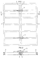
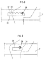
- Figures 1 and 2 correspond respectively to an upper view of two mutually attached concrete forming panels and to a cross-section through II-II of figure 1.
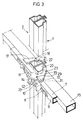
- Figure 3 shows a pictorial view of a clamping device according to the present invention.
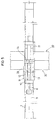
- Figure 4 corresponds to a cross-section of the clamping device, shown to attach two concrete forming panels.
- Figure 5 is an upper view corresponding to figure 4.
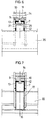
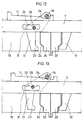
- Figure 6 and 7 show cross-sections of the clamping device through planes VI-VI and VII-VII shown in figure 4.
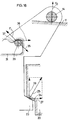
- Figures 8 and 9 show corresponding views of the lateral elongated openings of the U support which receives one of the transverse bolts of the swingeable structure.
- Figures 10 and 11 show two examples of eventual embodiments of the cross-sections of the beams constituting the frames for the forming panels.
- Figures 12, 13, 14 and 15 show respective successive tensioning steps of the swingeable structure of the clamping device of the present invention, starting from the loosened initial position, going through the stage in which the swingeable structure climbs on the steeper part of the wedge, up to the tensioning stage which corresponds to the section in which the wedge structure shows a lower inclination, ending in the final attachment position.
- Figure 16 shows the relative positions occupied by the two transverse bolts of the swingeable structure in relation with the lateral edges of the protrusion formed in the lateral openings of the rectangular support and the relative position of the effort bearing section on the frame forming beam, showing the vectors corresponding to the intervening forces.
- two adjacent concrete forming panels 1 and 2 are positioned adjacent to each other, on perimetral beams -3- and -4- constituting a part of the frames of such panels, attached by clamping means, in a variable number, as those shown with reference numerals -5- and -6- in figure 1.
- the clamping device essentially comprises a U section beam -7- which has a straight slit -8-extending lengthwise on one of the faces -9- of the beam and which is capable of receiving a movable wedge structure -10- to be guided on said slit and which has an upper face -11- with two successive inclined surfaces.
- the device will be completed by means of a swingeable structure which comprises two symetrically arranged side plates -12- and -13- which are attached by means of bolts -14- and -29-.
- the swingeable structure may rotate on said bolts and it is arranged in a form that the side plates will embrace the side faces of the U element - 7- and at the same time the corresponding side faces of beam -15- of one of the panels -1- to be attached.
- the clamping device has at the same time two side plates such as -17-, figure 3, integral with the lateral faces of beam -7-, having end hooks -18- which may adapt to side beam -22- of one of the panels -2- to be attached.
- Site plates -12- and -13- have intermediate recesses -19- which shape allows the mating, with a certain play, with the perimetral beam -20- of forming panel -1- to be attached.
- the ends -18-of plate -17- are capable of entering into recesses -21-of beam -22- of the other adjacent panel -2 to be attached.
- Component forces -27- and -27' - compress adjacent panels -1- and -2- together and component forces -26- and -26'-compress said panels against the support -7-, stiffening the assembly.
- the side elongated openings -31- may adopt the form shown in figure 8, with an ondulated upper edge, or alternatively the form shown in figure 9, which consists of a curved section -30- at one of the ends of the openings of any such form that generally may allow to have an intermediate angled section in such side openings -31-to obtain an additional force which may be represented by a vector directed in the sense of closing the clamping device.
- a series of forming panels may be assembled together and in case that the overall dimensions of the surface to be composed do not correspond to a multiple of the width of one panel, recourse will be taken to complementary elements to be inserted between said panels.
- the ondulated edge -31- in the example of figure 8 shows in its upper border a number of substantially semi-circular recesses and protrusions respectively -33-and -32- so that transverse bolt -29- may lodge itself within any of said recesses -33- depending on the width on which the present clamping device must be used, which will change according to the width defined by the forming panels and the eventual complementary elements to be used in case that the total width is not a multiple of the width of the individual forming panels.
- the bolt -29- of the swingeable structure will climb placing itself in the vicinity of one of the recesses -33- of the upper border of the opening.
- the bolt -29- will lodge itself in one of the recesses -33-and the swingeable structure constituted by elements -12-, -13, -14- and -29- will rotate on bolt -29- compressing its end portion -23- on the ramp -24- of the beam -20-generating a force which has been represented by vector -25- and by effect of the reaction, the same force will be exerted on beam -22- of adjacent plate -2- as previously stated.
- the bolt -29- will place itself in the curved section which is closer to its position.
- the opening -28- will have only one recess -30- for receiving the bolt -29- as shown in figure 9.
- Figures 12, 13, 14, and 15 show some successive stages of the clamping of the device
- the first of such figures shows the loose or tensionless situation of the device in which the swingeable structure rests by the transverse bolts -14 and -29- respectively, on the flat end surface of wedge -11- and on lower border of opening -31-.
Landscapes
- Engineering & Computer Science (AREA)
- Architecture (AREA)
- Mechanical Engineering (AREA)
- Civil Engineering (AREA)
- Structural Engineering (AREA)
- Forms Removed On Construction Sites Or Auxiliary Members Thereof (AREA)
- Mutual Connection Of Rods And Tubes (AREA)
Priority Applications (4)
| Application Number | Priority Date | Filing Date | Title |
|---|---|---|---|
| ES91500113T ES2084137T3 (es) | 1991-10-15 | 1991-10-15 | Dispositivo para la sujecion rapida de paneles para la construccion de estructuras de hormigon. |
| EP91500113A EP0537403B1 (de) | 1991-10-15 | 1991-10-15 | Vorrichtung zur Schnellverbindung von Schalungspanelen für Betonkonstruktionen |
| AT91500113T ATE131898T1 (de) | 1991-10-15 | 1991-10-15 | Vorrichtung zur schnellverbindung von schalungspanelen für betonkonstruktionen |
| DE69115698T DE69115698T2 (de) | 1991-10-15 | 1991-10-15 | Vorrichtung zur Schnellverbindung von Schalungspanelen für Betonkonstruktionen |
Applications Claiming Priority (1)
| Application Number | Priority Date | Filing Date | Title |
|---|---|---|---|
| EP91500113A EP0537403B1 (de) | 1991-10-15 | 1991-10-15 | Vorrichtung zur Schnellverbindung von Schalungspanelen für Betonkonstruktionen |
Publications (2)
| Publication Number | Publication Date |
|---|---|
| EP0537403A1 true EP0537403A1 (de) | 1993-04-21 |
| EP0537403B1 EP0537403B1 (de) | 1995-12-20 |
Family
ID=8208750
Family Applications (1)
| Application Number | Title | Priority Date | Filing Date |
|---|---|---|---|
| EP91500113A Expired - Lifetime EP0537403B1 (de) | 1991-10-15 | 1991-10-15 | Vorrichtung zur Schnellverbindung von Schalungspanelen für Betonkonstruktionen |
Country Status (4)
| Country | Link |
|---|---|
| EP (1) | EP0537403B1 (de) |
| AT (1) | ATE131898T1 (de) |
| DE (1) | DE69115698T2 (de) |
| ES (1) | ES2084137T3 (de) |
Cited By (7)
| Publication number | Priority date | Publication date | Assignee | Title |
|---|---|---|---|---|
| EP0552621B1 (de) * | 1992-01-23 | 1995-05-24 | Boulton Plc | Klemmvorrichtung für Platten |
| EP0674068A1 (de) * | 1994-01-22 | 1995-09-27 | PASCHAL-WERK G. MAIER GmbH | Klammer zum Verbinden von Schaltafeln mit deren Randprofile zusammendrückenden Spannbacken |
| DE19629660C1 (de) * | 1996-07-23 | 1997-11-20 | Maier G Paschal Werk | Klammer mit Spannbacken und einem diese verbindenden Träger |
| WO2001063073A1 (en) | 2000-02-24 | 2001-08-30 | Bauma S.A. | A lock for connecting boarding plates |
| WO2005007997A1 (de) | 2003-07-11 | 2005-01-27 | Peri Gmbh | Spannschlossvorrichtung mit schräg geführtem keil |
| WO2018211152A1 (es) * | 2017-05-15 | 2018-11-22 | Sistemas Tecnicos De Encofrados, S.A. | Panel para encofrados y sistema de encofrado que comprende dicho panel |
| KR20200060767A (ko) * | 2018-06-27 | 2020-06-01 | 광저우 리더 이큅먼트 리미티드 | 건축용 보드 연결 클램프 클립 |
Citations (7)
| Publication number | Priority date | Publication date | Assignee | Title |
|---|---|---|---|---|
| DE3609498A1 (de) * | 1985-12-20 | 1987-09-24 | Steidle Gmbh & Co Emil | Betonschalung |
| DE8622358U1 (de) * | 1986-08-21 | 1987-12-17 | Emil Steidle Gmbh & Co, 7480 Sigmaringen | Vorrichtung zum Verbinden zweier Schalungselemente |
| EP0304950A2 (de) * | 1987-08-26 | 1989-03-01 | Niels Dipl.-Ing. Hollmann | Rahmenschalungs-Verbindungsschloss |
| EP0375969A1 (de) * | 1988-12-28 | 1990-07-04 | THYSSEN HÜNNEBECK GmbH | Richtzwinge für Schalungssysteme |
| EP0404198A1 (de) * | 1989-06-23 | 1990-12-27 | Niels Dipl.-Ing. Hollmann | Rahmenschalungs-Verbindungsschloss |
| DE3941937A1 (de) * | 1989-12-19 | 1991-06-27 | Oesterr Doka Schalung | Spannschloss zum verbinden von rahmen-schalungselementen |
| DE4007950A1 (de) * | 1990-03-13 | 1991-09-19 | Huennebeck Roero Gmbh | Vorrichtung zum verbinden und verspannen von schaltafeln |
-
1991
- 1991-10-15 AT AT91500113T patent/ATE131898T1/de not_active IP Right Cessation
- 1991-10-15 DE DE69115698T patent/DE69115698T2/de not_active Expired - Fee Related
- 1991-10-15 ES ES91500113T patent/ES2084137T3/es not_active Expired - Lifetime
- 1991-10-15 EP EP91500113A patent/EP0537403B1/de not_active Expired - Lifetime
Patent Citations (7)
| Publication number | Priority date | Publication date | Assignee | Title |
|---|---|---|---|---|
| DE3609498A1 (de) * | 1985-12-20 | 1987-09-24 | Steidle Gmbh & Co Emil | Betonschalung |
| DE8622358U1 (de) * | 1986-08-21 | 1987-12-17 | Emil Steidle Gmbh & Co, 7480 Sigmaringen | Vorrichtung zum Verbinden zweier Schalungselemente |
| EP0304950A2 (de) * | 1987-08-26 | 1989-03-01 | Niels Dipl.-Ing. Hollmann | Rahmenschalungs-Verbindungsschloss |
| EP0375969A1 (de) * | 1988-12-28 | 1990-07-04 | THYSSEN HÜNNEBECK GmbH | Richtzwinge für Schalungssysteme |
| EP0404198A1 (de) * | 1989-06-23 | 1990-12-27 | Niels Dipl.-Ing. Hollmann | Rahmenschalungs-Verbindungsschloss |
| DE3941937A1 (de) * | 1989-12-19 | 1991-06-27 | Oesterr Doka Schalung | Spannschloss zum verbinden von rahmen-schalungselementen |
| DE4007950A1 (de) * | 1990-03-13 | 1991-09-19 | Huennebeck Roero Gmbh | Vorrichtung zum verbinden und verspannen von schaltafeln |
Cited By (17)
| Publication number | Priority date | Publication date | Assignee | Title |
|---|---|---|---|---|
| EP0552621B1 (de) * | 1992-01-23 | 1995-05-24 | Boulton Plc | Klemmvorrichtung für Platten |
| EP0674068A1 (de) * | 1994-01-22 | 1995-09-27 | PASCHAL-WERK G. MAIER GmbH | Klammer zum Verbinden von Schaltafeln mit deren Randprofile zusammendrückenden Spannbacken |
| US5570500A (en) * | 1994-01-22 | 1996-11-05 | Paschal-Werk G. Maier Gmbh | Clamp for connecting form panels with clamping jaws urging sections of panels together at their edges |
| TR28908A (tr) * | 1994-01-22 | 1997-08-04 | Maier G Paschal Werk | Döküm kaliplarinin baglanmasi icin kenar profillerini sikistiran sikma ceneli mandal. |
| DE19629660C1 (de) * | 1996-07-23 | 1997-11-20 | Maier G Paschal Werk | Klammer mit Spannbacken und einem diese verbindenden Träger |
| US5975483A (en) * | 1996-07-23 | 1999-11-02 | Paschal-Werk G. Maier Gmbh | Clamp with clamping jaws and a carrier connecting them |
| AU721439B2 (en) * | 1996-07-23 | 2000-07-06 | Paschal-Werk G. Maier Gmbh | A clamp with clamping jaws and a carrier connecting them |
| WO2001063073A1 (en) | 2000-02-24 | 2001-08-30 | Bauma S.A. | A lock for connecting boarding plates |
| WO2005007997A1 (de) | 2003-07-11 | 2005-01-27 | Peri Gmbh | Spannschlossvorrichtung mit schräg geführtem keil |
| DE10331359A1 (de) * | 2003-07-11 | 2005-02-03 | Peri Gmbh | Spannschlossvorrichtung mit schräg geführtem Keil |
| KR100892811B1 (ko) * | 2003-07-11 | 2009-04-10 | 페리 게엠베하 | 콘크리트 쉘 부재 및 턴버클 장치로 구성되는 콘크리트 쉘 시스템 |
| DE10331359B4 (de) * | 2003-07-11 | 2010-07-15 | Peri Gmbh | Spannschlossvorrichtung mit schräg geführtem Keil |
| US8104738B2 (en) | 2003-07-11 | 2012-01-31 | Peri Gmbh | Concrete shell system including clamping devices having diagonally guided wedges |
| WO2018211152A1 (es) * | 2017-05-15 | 2018-11-22 | Sistemas Tecnicos De Encofrados, S.A. | Panel para encofrados y sistema de encofrado que comprende dicho panel |
| EP3626910A4 (de) * | 2017-05-15 | 2020-12-09 | Sistemas Técnicos De Encofrados, S.A. | Schalungstafel und schalungssystem mit einer solchen tafel |
| KR20200060767A (ko) * | 2018-06-27 | 2020-06-01 | 광저우 리더 이큅먼트 리미티드 | 건축용 보드 연결 클램프 클립 |
| KR102429149B1 (ko) | 2018-06-27 | 2022-08-03 | 광저우 리더 이큅먼트 리미티드 | 건축용 보드 연결 클램프 클립 |
Also Published As
| Publication number | Publication date |
|---|---|
| ATE131898T1 (de) | 1996-01-15 |
| DE69115698D1 (de) | 1996-02-01 |
| DE69115698T2 (de) | 1996-08-01 |
| EP0537403B1 (de) | 1995-12-20 |
| ES2084137T3 (es) | 1996-05-01 |
Similar Documents
| Publication | Publication Date | Title |
|---|---|---|
| DE3838488C2 (de) | ||
| EP2246480B1 (de) | Kanaldiele und Kammerplatten-Verbaueinheit | |
| US5331754A (en) | Resilient, ratcheted wedge and spool retaining structure for an excavation tooth | |
| EP0537403A1 (de) | Vorrichtung zur Schnellverbindung von Schalungspanelen für Betonkonstruktionen | |
| US5137251A (en) | Pour window for a concrete form | |
| EP0038873B1 (de) | Stützfuss für fahrbare Fördergeräte | |
| DE69710076T3 (de) | U-förmige spundbohle mit niedrigem eintreibwiderstand | |
| KR102465258B1 (ko) | 안전 난간대 | |
| EP0370034B1 (de) | Verbindungsvorrichtung für schaltafeln | |
| DE2809329A1 (de) | Schalungsaufbau fuer eine baugruppe oder ein loch | |
| CH617482A5 (en) | Device for trench lining | |
| DE7816839U1 (de) | Gelenkige vorrichtung zum aussteifen der waende von baugraeben, rohrgraeben u.dgl. | |
| EP4499951B1 (de) | Spannschloss zum verspannen von rahmenschalungselementen | |
| DE509934T1 (de) | Verfahren zur fuehrung eines ausgrabungswerkzeugs fuer bodenschlitzwaende und ausgrabungswerkzeug zur durchfuehrung des verfahrens. | |
| DE3823763A1 (de) | Klammer zur verbindung der profilrahmen von rahmentafelschalungen | |
| DE2547019B1 (de) | Halterung zur loesbaren befestigung der zahnspitze eines baggerzahns | |
| DE2825710A1 (de) | Vorrichtung zum verbinden zweier schalungselemente einer betonschalung | |
| EP0012254A1 (de) | Verbindungsanordnung zwischen einzelnen Teilen eines Rammpfahles | |
| DE3920630A1 (de) | Rahmenschalungs-verbindungsschloss | |
| DE3445989A1 (de) | Keilschloss | |
| DE2729876A1 (de) | Bauteilverbindung, waermeisolierend, zur koppelung zweier bauteile | |
| DE3333857C1 (de) | Vorrichtung zum Verschieben schwerer Bauteile, insbesondere zum Vorschieben eines Unterwassertunnels | |
| DE544012C (de) | Decken- und Dachkonstruktion aus Betonplatten zwischen Traegern aus Eisen oder Eisenbeton | |
| DE19541610C2 (de) | Schalelement für den Betonbau | |
| JPH0542185Y2 (de) |
Legal Events
| Date | Code | Title | Description |
|---|---|---|---|
| PUAI | Public reference made under article 153(3) epc to a published international application that has entered the european phase |
Free format text: ORIGINAL CODE: 0009012 |
|
| AK | Designated contracting states |
Kind code of ref document: A1 Designated state(s): AT BE CH DE ES FR GB IT LI NL |
|
| 17P | Request for examination filed |
Effective date: 19930424 |
|
| 17Q | First examination report despatched |
Effective date: 19941117 |
|
| GRAA | (expected) grant |
Free format text: ORIGINAL CODE: 0009210 |
|
| AK | Designated contracting states |
Kind code of ref document: B1 Designated state(s): AT BE CH DE ES FR GB IT LI NL |
|
| REF | Corresponds to: |
Ref document number: 131898 Country of ref document: AT Date of ref document: 19960115 Kind code of ref document: T |
|
| REF | Corresponds to: |
Ref document number: 69115698 Country of ref document: DE Date of ref document: 19960201 |
|
| ITF | It: translation for a ep patent filed | ||
| REG | Reference to a national code |
Ref country code: CH Ref legal event code: NV Representative=s name: ANDRE BRAUN PATENTANWALT VSP |
|
| ET | Fr: translation filed | ||
| REG | Reference to a national code |
Ref country code: ES Ref legal event code: FG2A Ref document number: 2084137 Country of ref document: ES Kind code of ref document: T3 |
|
| PLBE | No opposition filed within time limit |
Free format text: ORIGINAL CODE: 0009261 |
|
| STAA | Information on the status of an ep patent application or granted ep patent |
Free format text: STATUS: NO OPPOSITION FILED WITHIN TIME LIMIT |
|
| 26N | No opposition filed | ||
| REG | Reference to a national code |
Ref country code: GB Ref legal event code: IF02 |
|
| PGFP | Annual fee paid to national office [announced via postgrant information from national office to epo] |
Ref country code: GB Payment date: 20030729 Year of fee payment: 13 |
|
| PGFP | Annual fee paid to national office [announced via postgrant information from national office to epo] |
Ref country code: NL Payment date: 20030731 Year of fee payment: 13 |
|
| PGFP | Annual fee paid to national office [announced via postgrant information from national office to epo] |
Ref country code: BE Payment date: 20030811 Year of fee payment: 13 |
|
| PGFP | Annual fee paid to national office [announced via postgrant information from national office to epo] |
Ref country code: AT Payment date: 20030812 Year of fee payment: 13 |
|
| PGFP | Annual fee paid to national office [announced via postgrant information from national office to epo] |
Ref country code: CH Payment date: 20031030 Year of fee payment: 13 |
|
| PG25 | Lapsed in a contracting state [announced via postgrant information from national office to epo] |
Ref country code: GB Free format text: LAPSE BECAUSE OF NON-PAYMENT OF DUE FEES Effective date: 20041015 Ref country code: AT Free format text: LAPSE BECAUSE OF NON-PAYMENT OF DUE FEES Effective date: 20041015 |
|
| PG25 | Lapsed in a contracting state [announced via postgrant information from national office to epo] |
Ref country code: CH Free format text: LAPSE BECAUSE OF NON-PAYMENT OF DUE FEES Effective date: 20041031 Ref country code: BE Free format text: LAPSE BECAUSE OF NON-PAYMENT OF DUE FEES Effective date: 20041031 Ref country code: LI Free format text: LAPSE BECAUSE OF NON-PAYMENT OF DUE FEES Effective date: 20041031 |
|
| PGFP | Annual fee paid to national office [announced via postgrant information from national office to epo] |
Ref country code: DE Payment date: 20041222 Year of fee payment: 14 |
|
| BERE | Be: lapsed |
Owner name: *UBINANA FELIX JOSE LUIS Effective date: 20041031 |
|
| PG25 | Lapsed in a contracting state [announced via postgrant information from national office to epo] |
Ref country code: NL Free format text: LAPSE BECAUSE OF NON-PAYMENT OF DUE FEES Effective date: 20050501 |
|
| GBPC | Gb: european patent ceased through non-payment of renewal fee |
Effective date: 20041015 |
|
| REG | Reference to a national code |
Ref country code: CH Ref legal event code: PL |
|
| NLV4 | Nl: lapsed or anulled due to non-payment of the annual fee |
Effective date: 20050501 |
|
| PGFP | Annual fee paid to national office [announced via postgrant information from national office to epo] |
Ref country code: FR Payment date: 20050819 Year of fee payment: 15 |
|
| PG25 | Lapsed in a contracting state [announced via postgrant information from national office to epo] |
Ref country code: IT Free format text: LAPSE BECAUSE OF NON-PAYMENT OF DUE FEES;WARNING: LAPSES OF ITALIAN PATENTS WITH EFFECTIVE DATE BEFORE 2007 MAY HAVE OCCURRED AT ANY TIME BEFORE 2007. THE CORRECT EFFECTIVE DATE MAY BE DIFFERENT FROM THE ONE RECORDED. Effective date: 20051015 |
|
| PG25 | Lapsed in a contracting state [announced via postgrant information from national office to epo] |
Ref country code: DE Free format text: LAPSE BECAUSE OF NON-PAYMENT OF DUE FEES Effective date: 20060503 |
|
| REG | Reference to a national code |
Ref country code: FR Ref legal event code: ST Effective date: 20070629 |
|
| BERE | Be: lapsed |
Owner name: *UBINANA FELIX JOSE LUIS Effective date: 20041031 |
|
| PG25 | Lapsed in a contracting state [announced via postgrant information from national office to epo] |
Ref country code: FR Free format text: LAPSE BECAUSE OF NON-PAYMENT OF DUE FEES Effective date: 20061031 |
|
| PGFP | Annual fee paid to national office [announced via postgrant information from national office to epo] |
Ref country code: ES Payment date: 20100913 Year of fee payment: 20 |
|
| REG | Reference to a national code |
Ref country code: ES Ref legal event code: FD2A Effective date: 20120110 |
|
| PG25 | Lapsed in a contracting state [announced via postgrant information from national office to epo] |
Ref country code: ES Free format text: LAPSE BECAUSE OF EXPIRATION OF PROTECTION Effective date: 20111016 |