EP0537441B2 - Méthode et dispositif pour la mesure des positions des roues d'une automobile - Google Patents
Méthode et dispositif pour la mesure des positions des roues d'une automobile Download PDFInfo
- Publication number
- EP0537441B2 EP0537441B2 EP92113926A EP92113926A EP0537441B2 EP 0537441 B2 EP0537441 B2 EP 0537441B2 EP 92113926 A EP92113926 A EP 92113926A EP 92113926 A EP92113926 A EP 92113926A EP 0537441 B2 EP0537441 B2 EP 0537441B2
- Authority
- EP
- European Patent Office
- Prior art keywords
- wheel
- motor vehicle
- positions
- detector
- level
- Prior art date
- Legal status (The legal status is an assumption and is not a legal conclusion. Google has not performed a legal analysis and makes no representation as to the accuracy of the status listed.)
- Expired - Lifetime
Links
Images


Classifications
-
- G—PHYSICS
- G01—MEASURING; TESTING
- G01B—MEASURING LENGTH, THICKNESS OR SIMILAR LINEAR DIMENSIONS; MEASURING ANGLES; MEASURING AREAS; MEASURING IRREGULARITIES OF SURFACES OR CONTOURS
- G01B5/00—Measuring arrangements characterised by the use of mechanical techniques
- G01B5/24—Measuring arrangements characterised by the use of mechanical techniques for measuring angles or tapers; for testing the alignment of axes
- G01B5/255—Measuring arrangements characterised by the use of mechanical techniques for measuring angles or tapers; for testing the alignment of axes for testing wheel alignment
-
- B—PERFORMING OPERATIONS; TRANSPORTING
- B60—VEHICLES IN GENERAL
- B60G—VEHICLE SUSPENSION ARRANGEMENTS
- B60G2200/00—Indexing codes relating to suspension types
- B60G2200/40—Indexing codes relating to the wheels in the suspensions
- B60G2200/46—Indexing codes relating to the wheels in the suspensions camber angle
-
- B—PERFORMING OPERATIONS; TRANSPORTING
- B60—VEHICLES IN GENERAL
- B60G—VEHICLE SUSPENSION ARRANGEMENTS
- B60G2200/00—Indexing codes relating to suspension types
- B60G2200/40—Indexing codes relating to the wheels in the suspensions
- B60G2200/462—Toe-in/out
-
- B—PERFORMING OPERATIONS; TRANSPORTING
- B60—VEHICLES IN GENERAL
- B60G—VEHICLE SUSPENSION ARRANGEMENTS
- B60G2200/00—Indexing codes relating to suspension types
- B60G2200/40—Indexing codes relating to the wheels in the suspensions
- B60G2200/462—Toe-in/out
- B60G2200/4622—Alignment adjustment
-
- B—PERFORMING OPERATIONS; TRANSPORTING
- B60—VEHICLES IN GENERAL
- B60G—VEHICLE SUSPENSION ARRANGEMENTS
- B60G2206/00—Indexing codes related to the manufacturing of suspensions: constructional features, the materials used, procedures or tools
- B60G2206/01—Constructional features of suspension elements, e.g. arms, dampers, springs
- B60G2206/90—Maintenance
- B60G2206/93—Tools used for adjustments
Definitions
- the invention relates to a method and Device for determining wheel positions a motor vehicle in which certain angular positions of a motor vehicle wheel can be determined.
- the level is defined by the height difference, which is supported by the wheel Motor vehicle part, for example that Chassis of the vehicle, versus an unsprung one Motor vehicle part, for example with suspension part directly connected to the wheel. Based on Figures 1 and 2, this should Connection with a wheel suspension Motor vehicle wheel are explained.
- a wheel hub 16 suspended suspension part 14 of the wheel suspension are an upper handlebar lever 15 and a lower one Handlebar lever 13 of the wheel suspension articulated.
- a sprung Motor vehicle part 12 for example that Chassis, not shown with the interposition Springs, shock absorbers and the like, on the suspension part 14, which carries the wheel hub 16, suspended.
- Level a is defined by the difference in height (h1 - h2) which a pivot point 6 for the sprung motor vehicle part 12 on the lower handlebar 13 and a pivot point 7 of the lower Handlebar lever 13 on the unsprung suspension part 14 in each case opposite the surface 17 occupies. If the suspension and the wheel with the normal weight of the suspended Automotive 12 is loaded, take the Components of the wheel suspension and the wheel which in 1 position shown.
- the suspension is designed to ensure be that the wheel with the underground at all has good contact with possible driving situations, so that the desired driving characteristics of the Motor vehicle remain guaranteed. To do this ensure the wheel position in all its Parameters (track, camber, caster and spread) adapt to the movements of the wheel suspension. This is due to certain laws, by the dimensions and by the arrangement of the kinematic elements of the Suspension are set. Depending on the requirements, that of the motor vehicle manufacturers at the Wants to meet driving characteristics of the motor vehicle, the suspension different Motor vehicles strong in their geometric data from each other. In most cases they are Motor vehicle maintenance workshops the geometric data are not known. Self if these are known, the geometric is known Behavior of the wheel suspension as a function different levels due to vehicle loading and other factors not. The Motor vehicle manufacturers therefore provide correlation tables, which the dependence of the wheel positions, in particular Wheel angle positions, from the level of Suspension included and also reference values specify where the wheel positions, in particular Angular positions to be measured.
- the respective provision the level of suspension i.e. the measurement the distance between the wheel suspension difficulties in the workshops prepares, especially what the accuracy of this Measurement concerned.
- the level of suspension i.e. the measurement the distance between the wheel suspension difficulties in the workshops prepares, especially what the accuracy of this Measurement concerned.
- DE-A-34 32 781 is a measuring device to determine the wheel positions of a Motor vehicle, especially when driving, known.
- the measuring device essentially consists from a hinge mechanism that on the one hand via an adapter with the wheel or the wheel carrier connectable and on the other hand with a body-fixed Support part is connected.
- the possibilities of movement on the hinge mechanism detected with a rotary encoder.
- With the Measuring device can track and camber angles of a Wheel as well as the spatial coordinates of a Point on the wheel axis can be determined.
- EP 0 280 941 A1 discloses wheel positions of motor vehicle mounted Measure wheels without contact using laser beams. From DE 35 13 316 C2 it is known to adjust the wheel track in the manufacture of motor vehicles Height difference between the two tie rod joints both by scanning the Wheel rim as well as by scanning a body part near the upper tie rod joint to determine and then to set the wheel track which for the measured Value of the height difference is provided.
- the object of the invention is therefore a universal Applicable measuring method for level determination to create so that this reproducible be taken into account when measuring the wheel position can, and a device of the aforementioned Kind of creating yourself without difficulty integrate into common wheel position measuring systems leaves.
- a body part for example the outer edge of the fender of the motor vehicle, from the wheel center (wheel axle) and the associated wheel positions, in particular Angular positions, measured.
- the different vertical distances for example due to different loads on the body manufacture the motor vehicle.
- you can that of the car manufacturers in the tables specified reference values are taken into account.
- the determined measured values then become Determination of a dependency of the wheel position related in level. On this way it is possible, according to the Specifications of the car manufacturer's correlations to determine between level and wheel position. However, it is also possible, generally Dependence of the wheel position on the level without Specifications of the motor vehicle manufacturers for everyone Determine vehicle type.
- the center of rotation (Axis of the wheel) for determining the position the unsprung components of the wheel suspension used.
- the wheel axis can be easily using a conventional adapter with which the detector for detecting the wheel positions, in particular Angular positions, attached to the wheel will determine. The level measurement can therefore in the measuring process in which the wheel position is measured, integrate easily.
- a distance measuring device For carrying out the level determination a distance measuring device is provided which the vertical distance between the center of the wheel, which through the one attached to the wheel via the adapter Detector or through a component of the adapter is determined, and the spring-loaded already mentioned Motor vehicle part, in particular body part, determined.
- the detector and adapter are centered on Motor vehicle wheel attached. It can be a self-centering adapter used become.
- the detector with which the distance measuring device is a detector for Wheel position measurement, for example for one or more of the wheel position parameters track, Fall, spread, caster.
- Detectors are used as in the older ones however not previously published German patent applications P 40 39 881 and P 41 01 047.7 are described.
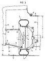
- FIG. 3 there is a motor vehicle wheel 1 from disc wheel and mounted pneumatic tire, shown.
- the chassis hereinafter with a sprung vehicle part 12
- This suspension is shown schematically in FIG. 3 and exists from an upper handlebar lever 15 and one lower handlebar 13.
- upper handlebar 15 is at a pivot point 18 on the sprung motor vehicle part 12 and at a pivot point 19 a non-sprung part 14 of the suspension articulated.
- the lower handlebar 13 is on one Articulation point 6 with the motor vehicle main part 12 and with a pivot point 7 on the non-sprung Part 14 of the suspension articulated.
- the unsprung Part 14 also carries a wheel hub 16 which the motor vehicle wheel 1 in a known manner is attached. Through the wheel hub 16 is a wheel axle M defines the center of rotation of the Rotation of the wheel forms.
- a detector 3 is defined opposite the wheel axis M attached to the motor vehicle wheel 1.
- the detector 3 is designed in a known manner and is used to measure the wheel position, for example to measure the camber angle c. He can also be used to measure other wheel position angles, such as track, lead and Spread, serve.
- a distance sensor 4 is provided with the detector 3 coupled so that the distance sensor 4 opposite the wheel axis M assumes a defined position.
- the distance sensor 4 can be in the housing of the detector 3 may be arranged.
- a potentiometer is particularly suitable Rotary potentiometer with a wire 20 a reference element 8, for example in the form a rod is connected.
- the reference element 8 can be rigidly connected to the vehicle body 12 connected vehicle part, in particular body part, e.g. the outer edge of the vehicle fender, which is vertically above the wheel axis M, attached become.
- the attachment can, for example, with With the help of a fastening screw.
- the extension length of the wire 20, which from the distance sensor 4 e.g.
- rotary potentiometer is detected a measure of the vertical distance b between the Outer edge of the fender and the wheel axle M.
- the wheel axis M keeps opposite the articulation point 7, for which the distance h2 from the surface 17 at the level determination is decisive, one constant distance over the wheel hub and the 16 suspension part 14. Furthermore, this is in vertical Distance above the wheel axis M.
- Body part with which the reference element 8 is connected for example the outer edge of the fender rigid with the articulation point 6, which determining for the distance h1 from the background 17 connected.
- the vertical distance b between the wheel axis M and the resiliently suspended automotive part for example the outer fender edge 5
- the distance sensor 4 can a the distance b, i.e. proportional to the level a electrical signal are generated, which then, as will be explained further processing.
- an extendable wire or wheel 20 or a cord between the rod-shaped Reference element 8 and the one designed as a potentiometer Distance sensor 4 can be the distance measuring device also as optical distance measurement with the help of mirrors and light sources, where, for example, the reference element 8 is represented by a mirror his.
- the reference element 8 is represented by a mirror his.
- the measuring principles for Come into use which in the older German Patent applications P 40 39 881 and P 41 01 047 are described.
- the level a (h1 - h2) as the wheel position can also be determined.
- the Level measurement an integral part of the wheel position measurement.
- the level measurement arrangement consisting from components 4, 8 and 20, which as Distance measuring device is formed can completely integrated in the measuring arrangement of the detector 3 his.
- Level values are determined.
- the different measurements can be considered of vehicle manufacturer specifications are executed, with certain requirements for the motor vehicle load and / or various Level values a0, a1 Vietnamese can be adhered to.
- d0, d1 ?? dn are the angle values referred to, which is not that of the motor vehicle manufacturer correspond to predetermined angle values, but with any level changes b0, b1 Across bn each result.
- the ones from Motor vehicle manufacturers specified values for different levels a0 Vietnamese across and wheel positions c0 ; cn can also be done in one with the computer 9 connected memory 10 may be stored.
- the different correlation values, which from Calculator 9 can also be determined in Memory 10 or in a separate memory are stored and stand for further measurement evaluation to disposal.
- the user can use a Interface 11 with the computer 9 in connection to step.
- the user can use an input keyboard or use similar input devices.
- a printer or a other display means for example a screen
Landscapes
- Physics & Mathematics (AREA)
- General Physics & Mathematics (AREA)
- Vehicle Body Suspensions (AREA)
- Length Measuring Devices With Unspecified Measuring Means (AREA)
- Body Structure For Vehicles (AREA)
- Electric Propulsion And Braking For Vehicles (AREA)
Claims (7)
- Procédé pour déterminer des positions de roue dans un véhicule automobile, selon lequel on mesure notamment des positions angulaires déterminées de la roue du véhicule automobile, en fonction du niveau respectif défini par la différence de hauteur que présente une partie du véhicule automobile supportée par la roue de façon suspendue, par rapport à une partie non suspendue du véhicule,
selon lequel on mesure directement plusieurs distances verticales différentes entre une partie de la carrosserie du véhicule automobile et le centre de la roue et on mesure en outre la position de roue associée,on met en relation les valeurs de mesure pour la détermination d'une dépendance de la position de roue vis-à-vis du niveau respectif, eton mémorise les relations déterminées de cette manière, en vue de leur réutilisation pour la détermination de positions de roues sur des véhicules automobiles du même type. - Procédé suivant la revendication 1, caractérisé par le fait qu'on mesure la différence verticale entre le bord extérieur de l'aile du véhicule automobile et le centre de la roue.
- Procédé suivant la revendication 1 ou 2, caractérisé par le fait qu'on détecte les valeurs de mesure pour au moins trois distances verticales différentes entre la partie de la carrosserie et le centre de la roue.
- Dispositif pour déterminer des positions de roue conformément au procédé suivant la revendication 1, sur un véhicule comportant un détecteur fixé à la roue du véhicule au moyen d'un adaptateur et servant à effectuer des mesures angulaires, et un dispositif de mesure de distance (4,8) servant à mesurer la distance verticale (b) entre le centre de la roue et une partie de la carrosserie du véhicule automobile, caractérisé par le fait que le dispositif de mesure de distance (4,8) et le détecteur (3) sont reliés à un calculateur (9), qui met en rapport les valeurs de mesure des distances verticales et les positions de roue respectivement associées, et détermine un ou plusieurs facteurs de corrélation pour la dépendance de la position de roue vis-à-vis du niveau, et en ce que le dispositif de mesure de distance (4, 8) est tel qu'il mesure directement la distance verticale entre la partie de la carrosserie du véhicule automobile et le milieu de la roue.
- Dispositif suivant la revendication 4, caractérisé par le fait que le dispositif de mesure de distance est accouplé au détecteur (3), qui est relié à la roue par l'intermédiaire de l'adaptateur (2) et qui exécute la mesure de la position de roue.
- Dispositif suivant la revendication 5, caractérisé par le fait que le détecteur (3) détecte l'angle de carrossage de la roue.
- Dispositif suivant l'une des revendications 4 à 6, caractérisé par le fait que la ou les valeurs de corrélation sont mémorisées dans une mémoire (10).
Applications Claiming Priority (2)
| Application Number | Priority Date | Filing Date | Title |
|---|---|---|---|
| DE4134411A DE4134411C2 (de) | 1991-10-17 | 1991-10-17 | Verfahren und Vorrichtung zur Messung von Radstellungen an einem Kraftfahrzeug |
| DE4134411 | 1991-10-17 |
Publications (3)
| Publication Number | Publication Date |
|---|---|
| EP0537441A1 EP0537441A1 (fr) | 1993-04-21 |
| EP0537441B1 EP0537441B1 (fr) | 1995-08-02 |
| EP0537441B2 true EP0537441B2 (fr) | 2001-04-25 |
Family
ID=6442904
Family Applications (1)
| Application Number | Title | Priority Date | Filing Date |
|---|---|---|---|
| EP92113926A Expired - Lifetime EP0537441B2 (fr) | 1991-10-17 | 1992-08-14 | Méthode et dispositif pour la mesure des positions des roues d'une automobile |
Country Status (4)
| Country | Link |
|---|---|
| US (1) | US5452606A (fr) |
| EP (1) | EP0537441B2 (fr) |
| DE (1) | DE4134411C2 (fr) |
| ES (1) | ES2076633T5 (fr) |
Families Citing this family (17)
| Publication number | Priority date | Publication date | Assignee | Title |
|---|---|---|---|---|
| DE19634505C1 (de) * | 1996-08-27 | 1997-11-20 | Daimler Benz Ag | Verfahren zur Erfassung der Achsgeometrie bei Kraftfahrzeugen mit Einzelradaufhängungen |
| DE19704954A1 (de) * | 1997-02-10 | 1998-08-13 | Itt Mfg Enterprises Inc | Verfahren zur verbesserten Bestimmung eines Raddrehzahlsignales und/oder eines Schlupfsignales |
| US6035729A (en) * | 1997-07-31 | 2000-03-14 | Weinmann; Thomas | Wheel offset measure |
| DE19753204C1 (de) * | 1997-12-01 | 1999-05-27 | Daimler Chrysler Ag | Verfahren und Vorrichtung zur Einstellung des Sturzes von Fahrzeugrädern |
| US6473978B1 (en) | 1998-06-16 | 2002-11-05 | Schenck Pegasus Corporation | Wheel alignment assembly and method |
| DE19829189C1 (de) * | 1998-06-30 | 2000-01-13 | Bosch Gmbh Robert | Vorrichtung zur Vermessung von Radachsen von Kraftfahrzeugen |
| US6237234B1 (en) * | 1999-09-28 | 2001-05-29 | Snap-On Technologies, Inc. | Method and apparatus for measuring vehicle wheel roll radius |
| DE10135362C1 (de) * | 2001-07-20 | 2002-10-10 | Daimler Chrysler Ag | Verfahren zur Beurteilung der Fahrwerksgeometrie |
| WO2004001365A1 (fr) * | 2002-06-19 | 2003-12-31 | Honda Giken Kogyo Kabushiki Kaisha | Dispositif et procede pour mesurer la position d'un element de reglage de l'angle d'inclinaison d'une roue, dispositif de reglage de piece du type arbre, et procede de mise en place de piece du type arbre |
| JP2004203225A (ja) * | 2002-12-25 | 2004-07-22 | Pacific Ind Co Ltd | タイヤ状態監視装置 |
| US7249418B2 (en) * | 2004-11-12 | 2007-07-31 | Hella KG a.A. Hueck & Co. | Wheel position sensor |
| US7331211B2 (en) * | 2005-02-10 | 2008-02-19 | Mitchell Craig Harrill | Apparatus for measuring suspension parameters which include roll center |
| US20080173080A1 (en) * | 2006-07-17 | 2008-07-24 | Strauser John W | Nascar body dimension or configuration measuring device |
| US9476800B2 (en) * | 2011-06-24 | 2016-10-25 | Bridgestone Americas Tire Operations, Llc | Wheel measurement apparatus |
| FR2987023B1 (fr) * | 2012-02-17 | 2014-10-31 | Peugeot Citroen Automobiles Sa | Dispositif et procedes de controle dimensionnel du recouvrement d'une roue d'un vehicule automobile |
| CN105526900B (zh) * | 2015-10-30 | 2018-04-24 | 中信戴卡股份有限公司 | 测量轮毂斜面壁厚尺寸的方法 |
| US11993279B1 (en) * | 2019-08-19 | 2024-05-28 | Matthew MacGregor Roy | Automatically adjustable camber and caster for autonomous vehicle |
Citations (2)
| Publication number | Priority date | Publication date | Assignee | Title |
|---|---|---|---|---|
| EP0280941A1 (fr) † | 1987-02-18 | 1988-09-07 | Perceptron, Inc. | Appareil et procédé pour la détermination de la position des roues d'un véhicule |
| DE3513316C2 (fr) † | 1985-04-13 | 1989-07-13 | Gerhard 6686 Eppelborn De Lauer |
Family Cites Families (9)
| Publication number | Priority date | Publication date | Assignee | Title |
|---|---|---|---|---|
| BR7904147A (pt) * | 1978-06-30 | 1980-04-15 | Nortron Corp | Sistema,aparelho e processo para alinhamento de rodas |
| DE3402738A1 (de) * | 1983-01-31 | 1984-08-30 | Sun Electric Corp., Crystal Lake, Ill. | Vorrichtung zum einstellen der raeder von tandem-lastkraftwagen |
| US4615618A (en) * | 1984-06-21 | 1986-10-07 | Jvi Laser Systems Inc. | Apparatus for determining the relationship of vehicle thrust line, and body center line for use in wheel alignment |
| DE3432781A1 (de) * | 1984-09-06 | 1986-03-13 | Bayerische Motoren Werke AG, 8000 München | Messvorrichtung, insbesondere zur bestimmung der radstellungen eines kraftfahrzeugs im fahrbetrieb |
| DE3740777C1 (en) * | 1987-12-02 | 1989-02-23 | Ford Werke Ag | Device for dynamic axle measurement on motor vehicles |
| US4977524A (en) * | 1989-01-03 | 1990-12-11 | Hunter Engineering Company | Electronic measuring gauge and apparatus for accurate vehicle stance diagnosis and guidance in effecting wheel alignment |
| US4942666A (en) * | 1989-11-28 | 1990-07-24 | Chart Industries Ltd. | Apparatus for measuring camber, caster and steering axis inclination of a vehicle |
| DE4039881C2 (de) * | 1990-12-13 | 1997-04-30 | Hofmann Werkstatt Technik | Verfahren und Vorrichtung zum optischen Messen eines Winkels, den Radstellungen an Fahrzeugen zueinander bilden |
| DE4101047C2 (de) * | 1991-01-16 | 1994-08-11 | Hofmann Werkstatt Technik | Vorrichtung zur optischen Messung eines Winkels, den ein Rad an einem Kraftfahrzeug bezüglich einer vertikalen Ebene einnimmt |
-
1991
- 1991-10-17 DE DE4134411A patent/DE4134411C2/de not_active Expired - Fee Related
-
1992
- 1992-08-14 EP EP92113926A patent/EP0537441B2/fr not_active Expired - Lifetime
- 1992-08-14 ES ES92113926T patent/ES2076633T5/es not_active Expired - Lifetime
-
1994
- 1994-07-29 US US08/281,977 patent/US5452606A/en not_active Expired - Fee Related
Patent Citations (2)
| Publication number | Priority date | Publication date | Assignee | Title |
|---|---|---|---|---|
| DE3513316C2 (fr) † | 1985-04-13 | 1989-07-13 | Gerhard 6686 Eppelborn De Lauer | |
| EP0280941A1 (fr) † | 1987-02-18 | 1988-09-07 | Perceptron, Inc. | Appareil et procédé pour la détermination de la position des roues d'un véhicule |
Also Published As
| Publication number | Publication date |
|---|---|
| DE4134411C2 (de) | 1997-01-16 |
| DE4134411A1 (de) | 1993-04-22 |
| EP0537441B1 (fr) | 1995-08-02 |
| EP0537441A1 (fr) | 1993-04-21 |
| ES2076633T3 (es) | 1995-11-01 |
| ES2076633T5 (es) | 2001-08-01 |
| US5452606A (en) | 1995-09-26 |
Similar Documents
| Publication | Publication Date | Title |
|---|---|---|
| EP0537441B2 (fr) | Méthode et dispositif pour la mesure des positions des roues d'une automobile | |
| DE69613259T2 (de) | Verfahren und Vorrichtung zum Messen des dynamischen Sturzes eines Fahrzeugreifens | |
| EP0521254B2 (fr) | Dispositif pour mesurer la position d'une roue | |
| DE60120628T2 (de) | Beladungsschätzer | |
| DE69206936T2 (de) | Geräte und Methode zur Eichung eines Niveauregelungsmoduls | |
| EP0241493B1 (fr) | Dispositif avec au moins deux liens rigides | |
| EP1281057B1 (fr) | Programme électronique de stabilité (ESP) pour banc d'essai vibratoire à rouleaux | |
| EP0774646B1 (fr) | Procédé et dispositif pour vérifier l'alignement des axes et des roues de voitures automobiles | |
| EP1002676A2 (fr) | Procédé de régulation du niveau et véhicule à roues équipé avec un système de régulation du niveau | |
| DE102006001436B4 (de) | Verfahren zum Bestimmen wenigstens eines Bewegungszustands eines Fahrzeugaufbaus | |
| DE69838124T2 (de) | Steuereinrichtung der Leuchtrichtung eines Kfz-Scheinwerfers | |
| EP1591770A1 (fr) | Procédé de contrôle des amortisseurs dans les véhicules automobiles | |
| DE102010003205A1 (de) | Verfahren zur Bestimmung der vertikalen Beschleunigung, der longitudinalen Winkelbeschleunigung und der transversalen Winkelbeschleunigung eines Körpers, insbesondere eines Kraftfahrzeugs | |
| EP1760446B1 (fr) | Banc d'essai du fonctionnement de véhicule | |
| EP0292855B1 (fr) | Procédé et dispositif pour contrôler et ajuster les mécanismes de roulement des véhicules | |
| DE19634505C1 (de) | Verfahren zur Erfassung der Achsgeometrie bei Kraftfahrzeugen mit Einzelradaufhängungen | |
| DE10337212B4 (de) | System und Verfahren zur Ermittlung eines Beladungszustandes eines Fahrzeugs oder eines Anhängers | |
| EP0259513B1 (fr) | Procédé pour mesurer avec précision le carrosage et l'inclination du pivot de véhicules | |
| DE4427483C1 (de) | Verfahren und Vorrichtung zum Vermessen von KFZ-Achsen und -Radstellungen | |
| DE3136145A1 (de) | Geraet zum pruefen der fahrwerksgeometrie von kraftfahrzeugen | |
| EP0826945B1 (fr) | Clinomètre pour déterminer l'inclinaison de pièces de construction des véhicules automobiles | |
| DE102023107224B3 (de) | Fahrzeugprüfstand zur Durchführung eines simulierten Fahrbetriebs eines in dem Fahrzeugprüfstand befindlichen Fahrzeugs | |
| DE19825740A1 (de) | Verfahren und Vorrichtung zur Messung der Radstellungen an einem Fahrzeug | |
| DE4243104A1 (en) | Wheel alignment system for measuring alignment angles of wheels | |
| AT521309B1 (de) | Verfahren und messanordnung zur optischen bestimmung von fahrwerksparametern |
Legal Events
| Date | Code | Title | Description |
|---|---|---|---|
| PUAI | Public reference made under article 153(3) epc to a published international application that has entered the european phase |
Free format text: ORIGINAL CODE: 0009012 |
|
| AK | Designated contracting states |
Kind code of ref document: A1 Designated state(s): ES FR GB IT |
|
| 17P | Request for examination filed |
Effective date: 19930407 |
|
| 17Q | First examination report despatched |
Effective date: 19940630 |
|
| GRAA | (expected) grant |
Free format text: ORIGINAL CODE: 0009210 |
|
| AK | Designated contracting states |
Kind code of ref document: B1 Designated state(s): ES FR GB IT |
|
| ET | Fr: translation filed | ||
| ITF | It: translation for a ep patent filed | ||
| GBT | Gb: translation of ep patent filed (gb section 77(6)(a)/1977) |
Effective date: 19950922 |
|
| REG | Reference to a national code |
Ref country code: ES Ref legal event code: FG2A Ref document number: 2076633 Country of ref document: ES Kind code of ref document: T3 |
|
| PLBI | Opposition filed |
Free format text: ORIGINAL CODE: 0009260 |
|
| PLBF | Reply of patent proprietor to notice(s) of opposition |
Free format text: ORIGINAL CODE: EPIDOS OBSO |
|
| 26 | Opposition filed |
Opponent name: SCHENCK KOMEG GMBH Effective date: 19960430 |
|
| PLBF | Reply of patent proprietor to notice(s) of opposition |
Free format text: ORIGINAL CODE: EPIDOS OBSO |
|
| RDAH | Patent revoked |
Free format text: ORIGINAL CODE: EPIDOS REVO |
|
| APAC | Appeal dossier modified |
Free format text: ORIGINAL CODE: EPIDOS NOAPO |
|
| APAE | Appeal reference modified |
Free format text: ORIGINAL CODE: EPIDOS REFNO |
|
| APAC | Appeal dossier modified |
Free format text: ORIGINAL CODE: EPIDOS NOAPO |
|
| PLBQ | Unpublished change to opponent data |
Free format text: ORIGINAL CODE: EPIDOS OPPO |
|
| PLAB | Opposition data, opponent's data or that of the opponent's representative modified |
Free format text: ORIGINAL CODE: 0009299OPPO |
|
| R26 | Opposition filed (corrected) |
Opponent name: SCHENCK KOMEG GMBH Effective date: 19960430 |
|
| APCC | Communication from the board of appeal sent |
Free format text: ORIGINAL CODE: EPIDOS OBAPO |
|
| APCC | Communication from the board of appeal sent |
Free format text: ORIGINAL CODE: EPIDOS OBAPO |
|
| APCC | Communication from the board of appeal sent |
Free format text: ORIGINAL CODE: EPIDOS OBAPO |
|
| APAC | Appeal dossier modified |
Free format text: ORIGINAL CODE: EPIDOS NOAPO |
|
| PLAB | Opposition data, opponent's data or that of the opponent's representative modified |
Free format text: ORIGINAL CODE: 0009299OPPO |
|
| R26 | Opposition filed (corrected) |
Opponent name: SNAP-ON DEUTSCHLAND HOLDING GMBH Effective date: 19960430 |
|
| PLAW | Interlocutory decision in opposition |
Free format text: ORIGINAL CODE: EPIDOS IDOP |
|
| PGFP | Annual fee paid to national office [announced via postgrant information from national office to epo] |
Ref country code: ES Payment date: 20000719 Year of fee payment: 9 |
|
| REG | Reference to a national code |
Ref country code: GB Ref legal event code: 732E |
|
| REG | Reference to a national code |
Ref country code: FR Ref legal event code: TP |
|
| PLAW | Interlocutory decision in opposition |
Free format text: ORIGINAL CODE: EPIDOS IDOP |
|
| RAP2 | Party data changed (patent owner data changed or rights of a patent transferred) |
Owner name: SNAP-ON DEUTSCHLAND HOLDING GMBH |
|
| PUAH | Patent maintained in amended form |
Free format text: ORIGINAL CODE: 0009272 |
|
| 27A | Patent maintained in amended form |
Effective date: 20010425 |
|
| AK | Designated contracting states |
Kind code of ref document: B2 Designated state(s): ES FR GB IT |
|
| GBTA | Gb: translation of amended ep patent filed (gb section 77(6)(b)/1977) | ||
| ITF | It: translation for a ep patent filed | ||
| ET3 | Fr: translation filed ** decision concerning opposition | ||
| REG | Reference to a national code |
Ref country code: ES Ref legal event code: DC2A Kind code of ref document: T5 Effective date: 20010607 |
|
| PGFP | Annual fee paid to national office [announced via postgrant information from national office to epo] |
Ref country code: FR Payment date: 20010810 Year of fee payment: 10 |
|
| PGFP | Annual fee paid to national office [announced via postgrant information from national office to epo] |
Ref country code: GB Payment date: 20010813 Year of fee payment: 10 |
|
| REG | Reference to a national code |
Ref country code: GB Ref legal event code: IF02 |
|
| PG25 | Lapsed in a contracting state [announced via postgrant information from national office to epo] |
Ref country code: GB Free format text: LAPSE BECAUSE OF NON-PAYMENT OF DUE FEES Effective date: 20020814 |
|
| PG25 | Lapsed in a contracting state [announced via postgrant information from national office to epo] |
Ref country code: ES Free format text: LAPSE BECAUSE OF NON-PAYMENT OF DUE FEES Effective date: 20020815 |
|
| GBPC | Gb: european patent ceased through non-payment of renewal fee |
Effective date: 20020814 |
|
| PG25 | Lapsed in a contracting state [announced via postgrant information from national office to epo] |
Ref country code: FR Free format text: LAPSE BECAUSE OF NON-PAYMENT OF DUE FEES Effective date: 20030430 |
|
| REG | Reference to a national code |
Ref country code: FR Ref legal event code: ST |
|
| REG | Reference to a national code |
Ref country code: ES Ref legal event code: FD2A Effective date: 20030912 |
|
| PG25 | Lapsed in a contracting state [announced via postgrant information from national office to epo] |
Ref country code: IT Free format text: LAPSE BECAUSE OF NON-PAYMENT OF DUE FEES;WARNING: LAPSES OF ITALIAN PATENTS WITH EFFECTIVE DATE BEFORE 2007 MAY HAVE OCCURRED AT ANY TIME BEFORE 2007. THE CORRECT EFFECTIVE DATE MAY BE DIFFERENT FROM THE ONE RECORDED. Effective date: 20050814 |
|
| APAH | Appeal reference modified |
Free format text: ORIGINAL CODE: EPIDOSCREFNO |