EP0537449B1 - Elément de guidage pour normes de moule - Google Patents
Elément de guidage pour normes de moule Download PDFInfo
- Publication number
- EP0537449B1 EP0537449B1 EP92114458A EP92114458A EP0537449B1 EP 0537449 B1 EP0537449 B1 EP 0537449B1 EP 92114458 A EP92114458 A EP 92114458A EP 92114458 A EP92114458 A EP 92114458A EP 0537449 B1 EP0537449 B1 EP 0537449B1
- Authority
- EP
- European Patent Office
- Prior art keywords
- annular groove
- guide
- clamping element
- mould part
- ring
- Prior art date
- Legal status (The legal status is an assumption and is not a legal conclusion. Google has not performed a legal analysis and makes no representation as to the accuracy of the status listed.)
- Expired - Lifetime
Links
Images
Classifications
-
- B—PERFORMING OPERATIONS; TRANSPORTING
- B29—WORKING OF PLASTICS; WORKING OF SUBSTANCES IN A PLASTIC STATE IN GENERAL
- B29C—SHAPING OR JOINING OF PLASTICS; SHAPING OF MATERIAL IN A PLASTIC STATE, NOT OTHERWISE PROVIDED FOR; AFTER-TREATMENT OF THE SHAPED PRODUCTS, e.g. REPAIRING
- B29C45/00—Injection moulding, i.e. forcing the required volume of moulding material through a nozzle into a closed mould; Apparatus therefor
- B29C45/17—Component parts, details or accessories; Auxiliary operations
- B29C45/26—Moulds
- B29C45/2602—Mould construction elements
- B29C45/2606—Guiding or centering means
-
- B—PERFORMING OPERATIONS; TRANSPORTING
- B29—WORKING OF PLASTICS; WORKING OF SUBSTANCES IN A PLASTIC STATE IN GENERAL
- B29C—SHAPING OR JOINING OF PLASTICS; SHAPING OF MATERIAL IN A PLASTIC STATE, NOT OTHERWISE PROVIDED FOR; AFTER-TREATMENT OF THE SHAPED PRODUCTS, e.g. REPAIRING
- B29C33/00—Moulds or cores; Details thereof or accessories therefor
- B29C33/30—Mounting, exchanging or centering
- B29C33/303—Mounting, exchanging or centering centering mould parts or halves, e.g. during mounting
Definitions
- the invention relates to a shape normal with a cylindrical guide element which has an annular groove in which a clamping element is provided, the variable outer diameter of which is larger than the outer diameter of the guide element.
- Mold standards are tools that are used to manufacture plastic parts using the injection molding process.
- Guide elements are used in mold making to precisely guide molded parts so that they return to the precisely specified position each time the mold is opened. Manufacturing these guide elements with a defined fit is a problem.
- the permissible tolerances allow different fits, from a game fit to a press fit. With the tolerances that occur, the fit clearance can be sufficient to automatically let guide elements fall out of the mold. There is a risk of accident if such a guide element on a worker Feet falls.
- a guide element can be pressed so tightly into a fit that the replacement of the guide element is associated with great effort.
- the guide elements are ground in a pointed manner. However, this is associated with considerable effort.
- the clamping element consists of an elastically deformable hollow ring which is introduced into the annular groove and is filled with oil. Depending on the oil pressure, the outer diameter of the clamping element is variable; it can be larger than the outer diameter of the guide element. A defined sliding fit can be produced by choosing the outside diameter.
- the connection of the guide element with the molded part holding it takes place via the press fit described as disadvantageous.
- the clamping element is used to connect the guide element and a bore in the other molded part.
- the invention has for its object to provide a shape normal with a cylindrical guide element which not only has a defined sliding fit, but also ensures the required self-locking.
- This object is achieved in a shape normal of the type mentioned according to the invention in that the clamping element is an elastic ring which is used to produce a defined sliding seat with self-locking between the shape normal and the guide element in the ring groove.
- an O-ring made of rubber or plastic, a spring ring made of metal or a coil spring ring is provided as the clamping element.
- the guide element according to the invention makes it possible to produce a precisely defined sliding seat with self-locking, without narrowing the tolerances further. In addition, this design makes it possible to save considerable costs, since there is no need for conventional grinding between the tips.
- Guide elements are to be understood as centering sleeves, guide bushes or guide bolts, for example.
- the design of the annular groove is expediently adapted to the clamping element.
- it may have a semi-circular or semi-elliptical cross-section.
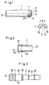
- the centering sleeve 1 shown in Fig. 1 is essentially hollow cylindrical. In the area of its end faces 11 and 12, it is chamfered both inside and outside. In the area of the end face 11, the centering sleeve 1 has an annular inner bead 13 with an internal thread 15 and an annular groove 14 on the outside.
- the annular groove 14 serves to receive a clamping element, in the exemplary embodiment an O-ring 4.
- the inner diameter of the O-ring 4 is equal to the diameter of the base of the groove; the outer diameter of the O-ring 4 is slightly larger than the outer diameter of the centering sleeve 1.
- the annular groove 14 has a rectangular cross section. It consists of two groove walls 16 and the groove base 17. Die Transitions from the groove walls 16 to the groove base 17 and to the outer surface of the centering sleeve 1 are rounded.
- the guide bushing 2 shown in FIG. 2 is also essentially hollow cylindrical.
- the guide bush 2 In the area of your end face 22, the guide bush 2 is chamfered on the inside; on the outside it has a stepped, reduced diameter.
- the guide bush In the area of the end face 21, the guide bush has a flange 23 of small diameter on the outside.
- the inside diameter of the guide bushing 2 is larger after the end face 21 than after the end face 22.
- the two inner parts of the guide bushing 2 are offset against each other by a shoulder 25.
- an annular groove 24 is introduced into the guide bushing 2, which receives the clamping element, in turn the O-ring 4 in the exemplary embodiment.
- the annular groove 24 is designed like the annular groove 14.
- the guide pin 3 shown in FIG. 3 has a guide part 31 which is divided by grooves 32 offset in the axial direction.
- a fitting part 35 adjoins the guide part 31 via a shoulder 33.
- An annular groove 34 is embedded in the fitting part 35.
- the annular groove 34 is designed like the annular groove 14.
- the annular groove 34 in turn receives the clamping element, in the exemplary embodiment the O-ring 4.
- the guide pin 3 is provided with a head 37 on the side of the collar 36 facing away from the fitting part 32.
- the O-ring 4 used as an exemplary embodiment can consist of rubber or plastic.
- a spring washer made of metal or a helical spring washer can also be used as the clamping element.
Landscapes
- Engineering & Computer Science (AREA)
- Mechanical Engineering (AREA)
- Manufacturing & Machinery (AREA)
- Clamps And Clips (AREA)
- Hand Tools For Fitting Together And Separating, Or Other Hand Tools (AREA)
- Control Of Indicators Other Than Cathode Ray Tubes (AREA)
- Optical Integrated Circuits (AREA)
- Bipolar Integrated Circuits (AREA)
- Snaps, Bayonet Connections, Set Pins, And Snap Rings (AREA)
Claims (5)
- Norme de moule avec un élément de guidage (1; 2; 3) cylindrique qui présente une rainure annulaire (14; 24; 34) dans laquelle est prévu un élément de blocage dont le diamètre extérieur variable est supérieur au diamètre extérieur de l'élément de guidage, caractérisée en ce que l'élément de blocage est une bague (4) élastique qui est insérée dans la rainure annulaire (14; 24; 34) pour obtenir un ajustement appuyé défini, avec autoblocage, entre la norme de moule et l'élément de guidage.
- Norme de moule selon la revendication 1, caractérisée en ce qu'il est prévu comme élément de blocage un joint torique (4) en caoutchouc ou en plastique.
- Norme de moule selon la revendication 1, caractérisée en ce qu'il est prévu comme élément de blocage une bague élastique en métal.
- Norme de moule selon la revendication 1, caractérisée en ce qu'il est prévu comme élément de blocage une bague à ressort hélicoïdal.
- Norme de moule selon l'une quelconque des revendications 1 à 4, caractérisée en ce que la rainure annulaire (14; 24; 34;) présente une section rectangulaire avec des transitions arrondies entre les parois de rainure (16), le fond de rainure (17) et la surface externe.
Applications Claiming Priority (2)
| Application Number | Priority Date | Filing Date | Title |
|---|---|---|---|
| DE9112959U | 1991-10-18 | ||
| DE9112959U DE9112959U1 (de) | 1991-10-18 | 1991-10-18 | Führungselement für Formnormalien |
Publications (2)
| Publication Number | Publication Date |
|---|---|
| EP0537449A1 EP0537449A1 (fr) | 1993-04-21 |
| EP0537449B1 true EP0537449B1 (fr) | 1995-10-25 |
Family
ID=6872365
Family Applications (1)
| Application Number | Title | Priority Date | Filing Date |
|---|---|---|---|
| EP92114458A Expired - Lifetime EP0537449B1 (fr) | 1991-10-18 | 1992-08-25 | Elément de guidage pour normes de moule |
Country Status (3)
| Country | Link |
|---|---|
| EP (1) | EP0537449B1 (fr) |
| AT (1) | ATE129448T1 (fr) |
| DE (2) | DE9112959U1 (fr) |
Families Citing this family (1)
| Publication number | Priority date | Publication date | Assignee | Title |
|---|---|---|---|---|
| DE9414189U1 (de) * | 1994-09-01 | 1994-11-10 | Siemens Nixdorf Informationssysteme AG, 33106 Paderborn | Mitnehmer |
Citations (1)
| Publication number | Priority date | Publication date | Assignee | Title |
|---|---|---|---|---|
| EP0338460A2 (fr) * | 1988-04-19 | 1989-10-25 | Heckler & Koch GmbH | Ensemble modulaire pour le maintien des pièces à usiner |
Family Cites Families (5)
| Publication number | Priority date | Publication date | Assignee | Title |
|---|---|---|---|---|
| DE1146227B (de) * | 1959-03-23 | 1963-03-28 | Fahr Ag Maschf | Fuehrungs- und Spannstift fuer Formkaesten |
| US3132557A (en) * | 1960-08-03 | 1964-05-12 | Northern Ordnance Inc | Friction type dowel and ring keeper therefor |
| DE3436182C1 (de) * | 1984-10-03 | 1985-11-14 | Karl 7298 Loßburg Hehl | Spritzgiessform fuer Kunststoff-Spritzgiessmaschine mit Verriegelungseinrichtung |
| DE3534937A1 (de) * | 1984-10-03 | 1986-04-10 | Karl 7298 Loßburg Hehl | Spritzgiessform fuer kunststoff-spritzgiessmaschine mit verriegelungseinrichtung |
| AT384396B (de) * | 1985-10-10 | 1987-11-10 | Meusburger Georg Ges M B H | Fuehrungshuelse und werkzeug zum ausziehen der fuehrungshuelse |
-
1991
- 1991-10-18 DE DE9112959U patent/DE9112959U1/de not_active Expired - Lifetime
-
1992
- 1992-08-25 DE DE59204125T patent/DE59204125D1/de not_active Expired - Fee Related
- 1992-08-25 EP EP92114458A patent/EP0537449B1/fr not_active Expired - Lifetime
- 1992-08-25 AT AT92114458T patent/ATE129448T1/de not_active IP Right Cessation
Patent Citations (1)
| Publication number | Priority date | Publication date | Assignee | Title |
|---|---|---|---|---|
| EP0338460A2 (fr) * | 1988-04-19 | 1989-10-25 | Heckler & Koch GmbH | Ensemble modulaire pour le maintien des pièces à usiner |
Also Published As
| Publication number | Publication date |
|---|---|
| EP0537449A1 (fr) | 1993-04-21 |
| DE59204125D1 (de) | 1995-11-30 |
| DE9112959U1 (de) | 1991-12-19 |
| ATE129448T1 (de) | 1995-11-15 |
Similar Documents
| Publication | Publication Date | Title |
|---|---|---|
| DE2922705C2 (de) | Verbinder für optische Fasern | |
| DE60205330T2 (de) | Einspritzdüse für Kunststoff-Spritzgerät | |
| DE3634383A1 (de) | Ringfoermiges maschinenteil | |
| EP0817987B1 (fr) | Charniere a ressort pour lunettes | |
| WO2008031655A1 (fr) | Dispositif de fixation pour une conduite | |
| DE2952468A1 (de) | Steckbare verbindungsvorrichtung mit schnappverschluss | |
| DE2845308C3 (de) | Fitting oder dergleichen aus formstabilem Kunststoff für Rohrverbindungen sowie Verfahren und Werkzeug zu seiner Herstellung | |
| EP0519524A2 (fr) | Dispositif de protection des extrémités de tuyaux | |
| DE102016219833A1 (de) | Spritzdüse für Kunststoffspritzgießvorrichtungen zur Herstellung von transparenten oder halbtransparenten ästhetischen Fahrzeugkomponenten, beispielsweise Linsen für Beleuchtung, und Spritzgießvorrichtung | |
| DE4233896C2 (de) | Kolben | |
| DE102008008562A1 (de) | Befestigungseinrichtung für eine Leitung | |
| DE3007858A1 (de) | Rollbalg-luftfeder und verfahren zu ihrem zusammenbau | |
| EP0537449B1 (fr) | Elément de guidage pour normes de moule | |
| EP0469325A2 (fr) | Procédé de fabrication de surfaces de glissement dans une douille de guidage en plastique pour colonne télescopique de chaise | |
| DE2322027A1 (de) | Werkzeughalter | |
| EP4390207B1 (fr) | Pièce d'accouplement pour un accouplement hydraulique | |
| DE4235611C2 (de) | Kunststoff-Lagergehäuse | |
| EP3572312A1 (fr) | Dispositif de commande, élément de centrage et maquette de montage pour bicyclette | |
| DE3039539A1 (de) | Zapfenanordnung zur anbringung eines gelenks | |
| WO1994026496A1 (fr) | Ejecteur de douilles | |
| DE2116188B2 (de) | Steuerschieberventil | |
| EP1253362A2 (fr) | Boítier d'une soupape à voies multiples | |
| DE10143644C1 (de) | Führungsbolzen für ein Spritzgieß- oder Presswerkzeug zur Verarbeitung von Kunststoff- und anderen plastischen Massen | |
| DE2145808A1 (de) | Einsatz für pneumatische Ventile, insbesondere für schlauchlose Reifen | |
| DE3152323T1 (de) | Schreibspitzenaufbau eines Schreibgerätes mit rohrenförmiger Schreibspitze |
Legal Events
| Date | Code | Title | Description |
|---|---|---|---|
| PUAI | Public reference made under article 153(3) epc to a published international application that has entered the european phase |
Free format text: ORIGINAL CODE: 0009012 |
|
| AK | Designated contracting states |
Kind code of ref document: A1 Designated state(s): AT BE CH DE DK ES FR GB GR IE IT LI LU MC NL PT SE |
|
| 17P | Request for examination filed |
Effective date: 19930902 |
|
| 17Q | First examination report despatched |
Effective date: 19940103 |
|
| GRAA | (expected) grant |
Free format text: ORIGINAL CODE: 0009210 |
|
| AK | Designated contracting states |
Kind code of ref document: B1 Designated state(s): AT BE CH DE DK ES FR GB GR IE IT LI LU MC NL PT SE |
|
| PG25 | Lapsed in a contracting state [announced via postgrant information from national office to epo] |
Ref country code: IT Free format text: LAPSE BECAUSE OF FAILURE TO SUBMIT A TRANSLATION OF THE DESCRIPTION OR TO PAY THE FEE WITHIN THE PRE;WARNING: LAPSES OF ITALIAN PATENTS WITH EFFECTIVE DATE BEFORE 2007 MAY HAVE OCCURRED AT ANY TIME BEFORE 2007. THE CORRECT EFFECTIVE DATE MAY BE DIFFERENT FROM THE ONE RECORDED.SCRIBED TIME-LIMIT Effective date: 19951025 Ref country code: ES Free format text: THE PATENT HAS BEEN ANNULLED BY A DECISION OF A NATIONAL AUTHORITY Effective date: 19951025 Ref country code: GR Free format text: LAPSE BECAUSE OF FAILURE TO SUBMIT A TRANSLATION OF THE DESCRIPTION OR TO PAY THE FEE WITHIN THE PRESCRIBED TIME-LIMIT Effective date: 19951025 Ref country code: MC Free format text: LAPSE BECAUSE OF NON-PAYMENT OF DUE FEES Effective date: 19951025 Ref country code: DK Effective date: 19951025 Ref country code: BE Effective date: 19951025 Ref country code: NL Free format text: LAPSE BECAUSE OF FAILURE TO SUBMIT A TRANSLATION OF THE DESCRIPTION OR TO PAY THE FEE WITHIN THE PRESCRIBED TIME-LIMIT Effective date: 19951025 |
|
| REF | Corresponds to: |
Ref document number: 129448 Country of ref document: AT Date of ref document: 19951115 Kind code of ref document: T |
|
| ET | Fr: translation filed | ||
| REG | Reference to a national code |
Ref country code: IE Ref legal event code: FG4D Free format text: 65837 |
|
| REF | Corresponds to: |
Ref document number: 59204125 Country of ref document: DE Date of ref document: 19951130 |
|
| GBT | Gb: translation of ep patent filed (gb section 77(6)(a)/1977) |
Effective date: 19951103 |
|
| PG25 | Lapsed in a contracting state [announced via postgrant information from national office to epo] |
Ref country code: PT Effective date: 19960125 Ref country code: SE Effective date: 19960125 |
|
| NLV1 | Nl: lapsed or annulled due to failure to fulfill the requirements of art. 29p and 29m of the patents act | ||
| PG25 | Lapsed in a contracting state [announced via postgrant information from national office to epo] |
Ref country code: IE Free format text: LAPSE BECAUSE OF NON-PAYMENT OF DUE FEES Effective date: 19960510 |
|
| REG | Reference to a national code |
Ref country code: IE Ref legal event code: FD4D Ref document number: 65837 Country of ref document: IE |
|
| PG25 | Lapsed in a contracting state [announced via postgrant information from national office to epo] |
Ref country code: AT Effective date: 19960825 |
|
| PLBE | No opposition filed within time limit |
Free format text: ORIGINAL CODE: 0009261 |
|
| PG25 | Lapsed in a contracting state [announced via postgrant information from national office to epo] |
Ref country code: LU Free format text: LAPSE BECAUSE OF NON-PAYMENT OF DUE FEES Effective date: 19960831 Ref country code: CH Effective date: 19960831 Ref country code: LI Effective date: 19960831 |
|
| 26N | No opposition filed | ||
| REG | Reference to a national code |
Ref country code: CH Ref legal event code: PL |
|
| PGFP | Annual fee paid to national office [announced via postgrant information from national office to epo] |
Ref country code: GB Payment date: 19990812 Year of fee payment: 8 |
|
| PGFP | Annual fee paid to national office [announced via postgrant information from national office to epo] |
Ref country code: FR Payment date: 19990823 Year of fee payment: 8 |
|
| PG25 | Lapsed in a contracting state [announced via postgrant information from national office to epo] |
Ref country code: GB Free format text: LAPSE BECAUSE OF NON-PAYMENT OF DUE FEES Effective date: 20000825 |
|
| GBPC | Gb: european patent ceased through non-payment of renewal fee |
Effective date: 20000825 |
|
| PG25 | Lapsed in a contracting state [announced via postgrant information from national office to epo] |
Ref country code: FR Free format text: LAPSE BECAUSE OF NON-PAYMENT OF DUE FEES Effective date: 20010430 |
|
| REG | Reference to a national code |
Ref country code: FR Ref legal event code: ST |
|
| PGFP | Annual fee paid to national office [announced via postgrant information from national office to epo] |
Ref country code: DE Payment date: 20040730 Year of fee payment: 13 |
|
| PG25 | Lapsed in a contracting state [announced via postgrant information from national office to epo] |
Ref country code: DE Free format text: LAPSE BECAUSE OF NON-PAYMENT OF DUE FEES Effective date: 20060301 |