EP0537480A2 - Magnetic circuit with air gap, particularly for ballasts for discharge lamps, and its manufacturing method - Google Patents
Magnetic circuit with air gap, particularly for ballasts for discharge lamps, and its manufacturing method Download PDFInfo
- Publication number
- EP0537480A2 EP0537480A2 EP92115602A EP92115602A EP0537480A2 EP 0537480 A2 EP0537480 A2 EP 0537480A2 EP 92115602 A EP92115602 A EP 92115602A EP 92115602 A EP92115602 A EP 92115602A EP 0537480 A2 EP0537480 A2 EP 0537480A2
- Authority
- EP
- European Patent Office
- Prior art keywords
- cable
- braid
- shield
- bridging
- unshielded
- Prior art date
- Legal status (The legal status is an assumption and is not a legal conclusion. Google has not performed a legal analysis and makes no representation as to the accuracy of the status listed.)
- Withdrawn
Links
Images

Classifications
-
- H—ELECTRICITY
- H02—GENERATION; CONVERSION OR DISTRIBUTION OF ELECTRIC POWER
- H02G—INSTALLATION OF ELECTRIC CABLES OR LINES, OR OF COMBINED OPTICAL AND ELECTRIC CABLES OR LINES
- H02G15/00—Cable fittings
- H02G15/08—Cable junctions
- H02G15/18—Cable junctions protected by sleeves, e.g. for communication cable
- H02G15/1806—Heat shrinkable sleeves
-
- H—ELECTRICITY
- H01—ELECTRIC ELEMENTS
- H01R—ELECTRICALLY-CONDUCTIVE CONNECTIONS; STRUCTURAL ASSOCIATIONS OF A PLURALITY OF MUTUALLY-INSULATED ELECTRICAL CONNECTING ELEMENTS; COUPLING DEVICES; CURRENT COLLECTORS
- H01R13/00—Details of coupling devices of the kinds covered by groups H01R12/70 or H01R24/00 - H01R33/00
- H01R13/648—Protective earth or shield arrangements on coupling devices, e.g. anti-static shielding
- H01R13/658—High frequency shielding arrangements, e.g. against EMI [Electro-Magnetic Interference] or EMP [Electro-Magnetic Pulse]
- H01R13/6591—Specific features or arrangements of connection of shield to conductive members
- H01R13/6592—Specific features or arrangements of connection of shield to conductive members the conductive member being a shielded cable
-
- H—ELECTRICITY
- H01—ELECTRIC ELEMENTS
- H01R—ELECTRICALLY-CONDUCTIVE CONNECTIONS; STRUCTURAL ASSOCIATIONS OF A PLURALITY OF MUTUALLY-INSULATED ELECTRICAL CONNECTING ELEMENTS; COUPLING DEVICES; CURRENT COLLECTORS
- H01R4/00—Electrically-conductive connections between two or more conductive members in direct contact, i.e. touching one another; Means for effecting or maintaining such contact; Electrically-conductive connections having two or more spaced connecting locations for conductors and using contact members penetrating insulation
- H01R4/70—Insulation of connections
- H01R4/72—Insulation of connections using a heat shrinking insulating sleeve
Definitions
- the invention relates to a shield bridging for unshielded cable end sections of a cable-connector connection, such as a cable-plug connection, and a method for applying this shield bridging to the unshielded cable end sections.
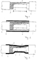
- Fig. 1 a conventional cable-plug connection is shown. It is common that the cable section 4 immediately adjacent to the connector 1 is not shielded over a length 1. So far there have been no restrictions on the permissible length of this unshielded section, so that these unshielded lengths were sometimes 200 mm or more.
- the object of the present invention is to provide a shield bridging for unshielded cable end sections of a cable connector connection, such as a cable-plug connection, and a method for applying this shield bridging to the unshielded cable end section.
- this object is achieved according to the invention in that the unshielded cable end section is surrounded over its entire length with an electrically 360 ° shielding metal braid.
- the metal braid consists of a band-shaped copper braid, the longitudinal edges of which are connected to one another.
- Another embodiment of the invention provides that the longitudinal edges are connected with the aid of an adhesive fixing agent, such as butyl rubber, applied on one side to at least one longitudinal edge.
- an adhesive fixing agent such as butyl rubber
- the shield bridging and the adjacent shielded cable section are surrounded by a shrunk-on hose material.
- a band-shaped copper braid is used as the metal braid, the longitudinal edges of which are connected to one another after the unshielded cable end section has been sheathed.
- an adhesive fixing agent e.g. Butyl rubber, adhesive strips or combinations of these, applied on one side to at least one longitudinal edge.
- the two longitudinal edges of the metal braid are brought into an overlapping position during wrapping and fixed in this position.
- a shrinkable hose provided on the inside with a hot-melt adhesive layer or a shrinkable hose with a conductive and tight inner layer is used.
- the shield bypass of the present invention can be easily applied to a non-shielded cable section after assembling a cable connector connection, such as a cable plug connector, provided that a shrinkable tube is kept on standby.
- the shielding made of a copper braid has a high attenuation, is flexible and adapts to the respective application, eg in the cable diameter. Furthermore, it is available on the market as a basic network, so that no costly additional production steps are required are necessary.
- the copper braid When exposed to external pressure, for example from a shrink tube, the copper braid largely adapts to the contours of the cable without reducing the shielding effect.
- the conventional cable-plug connection shown in Fig. 1 consists of a plug part 1, which is connected to a shielded cable.
- the cable section 4 directly adjoining the plug part is not shielded, since the shielding for the assembly of the plug part has been removed in this section.
- the rest of the cable is surrounded by a shield 3 and a sheath 2 for additional protection.
- the metallic shield is provided with an additional wire 5.
- the shield bridging according to the invention consists of a Cu metal braid, which is supplied either as a hose or tape material.
- the delivered material is first cut to a length which corresponds at least to the length 1 of the unshielded cable section 4.
- the unshielded cable section 4 is then covered with the previously cut copper braid.
- the shielding bridging 6 made of copper braid is still relatively loosely around the cable section 4, so that the position of the shielding bridging 6 can be changed relatively easily.
- the length of the shrinkable tube 7 must be selected so that both the shield bypass 6 is completely covered and part of the cable sheath 2 already present.
- a length of shrinkable tubing section is kept on standby in such a way that it is ready before the cable assembly, i.e. is pushed onto the cable before striking the plug part.
- the wire 5 is brought into a conductive connection with the Cu metal braid so that the braid serving as a bridge and the cable shield 3 have the same electrical potential.
- the shield bypass is fixed in its position and firmly connected to the part of the cable that has already been shielded.
- an external pressure is exerted on the shield bridging, under which the very flexible copper braid can largely adapt to the contours of the cable.
- a cable connector with a shield bypass is shown in the final state.
- the shield bridging according to the invention enables a reliable shielding of assembled Cable-connector connections, such as cable-plug connections.
- the copper braids used for this purpose consist of a prefabricated band, which can be obtained by cutting a braided hose.
- the tape is produced by cutting a braided hose, it is advantageous that the braid is previously fixed in the area of the cut edges with a suitable material. In this way it can be prevented that the braid becomes unstable after cutting and the edges "crumble".
- a material suitable for this application is, for example, the dual-sided adhesive tape described in patent application P 38 09 167.4, a laminate of butyl rubber and hot glue.
- This dual-sided adhesive tape is applied lengthways to the outside or inside of the braided hose, the butyl rubber being in direct contact with the braid, thus stabilizing it.
- the tube is then cut lengthways through the dual-sided adhesive tape.
- the outer edges of the copper braiding provided with the dual adhesive tape are used in use as longitudinal edges, the butyl rubber layer of which enables a connection.
- a piece of braided tape is placed around the cable section to be shielded and the two outer edges of the tape are connected to one another with the aid of the butyl rubber.
- the dimensions of the piece of braided tape used are matched to the respective application.
- the width of the braid tape should at least correspond to the circumference of the cable and the length at least to length 1 of the unshielded cable section. It has been found to be advantageous if the width of the braided tape is selected so that the two outer edges of the tape overlap after the piece of braided tape has been placed around the cable. In this way it can be ensured that the braid has 360 o contact after assembly, and thus completely shields.
- Fig. 4 shows a cut braided hose, which was provided with a dual adhesive tape before the separation.
- the two longitudinal edges consequently each have a part of the dual adhesive tape (9, 10).
- the two longitudinal edges are first connected to one another to form a tubular structure with the aid of butyl rubber 9 by means of butt bonding.
- the hot glue 8 of the dual adhesive tape is also liquefied, as a result of which the connection is additionally glued.
- the overlapping outer edges of the tape are additionally made by using suitable materials, e.g. a strip-shaped butyl rubber bead 9 (FIG. 5), an adhesive strip 10 (FIG. 7) or a combination of both (FIG. 6). These materials can either be applied between the overlapping outer edges of the tape or onto the transition from the outer edge of the braid to the tape.
- a conductive plastic as an adhesive to additionally secure a shield that is closed on all sides.
- a shrink tube with a conductive and sealing inner layer can also be used for this purpose.
Landscapes
- Shielding Devices Or Components To Electric Or Magnetic Fields (AREA)
- Insulated Conductors (AREA)
Abstract
Description
Die Erfindung betrifft eine Abschirmungsüberbrückung für nicht abgeschirmte Kabelendabschnitte einer Kabel-Verbinder-Verbindung, wie einer Kabel-Stecker-Verbindung und ein Verfahren zum Aufbringen dieser Abschirmungsüberbrückung auf die nicht abgeschirmten Kabelendabschnitte.The invention relates to a shield bridging for unshielded cable end sections of a cable-connector connection, such as a cable-plug connection, and a method for applying this shield bridging to the unshielded cable end sections.
In Fig. 1 ist eine herkömmliche Kabel-Stecker-Verbindung dargestellt. Dabei ist es üblich, daß der an den Stecker 1 unmittelbar angrenzende Kabelabschnitt 4 über eine Länge 1 nicht abgeschirmt ist. Für die zulässige Länge dieses nicht abgeschirmten Abschnittes gab es bisher keine Beschränkungen, so daß diese unabgeschirmten Längen bisweilen 200 mm oder mehr betrugen.In Fig. 1, a conventional cable-plug connection is shown. It is common that the
Durch den Trend der Industrie aus Platzersparnisgründen immer kompakter zu bauen, werden häufig Kabelbäume verwendet, so daß eine Vielzahl solcher Kabel-Stecker-Verbindungen dicht aneinander angeordnet sind. Folglich treten bedingt durch die nicht abgeschirmten Kabelabschnitte vermehrt elektronische Beeinflussungen der einzelnen Kabel untereinander auf.Due to the trend of the industry to build ever more compact to save space, cable harnesses are often used, so that a large number of such cable-plug connections are arranged close together. As a result, electronic cables are increasingly used due to the unshielded cable sections Influences of the individual cables on each other.
Um diese elektronischen Störungen zu vermeiden, wird jetzt von Kabelbaumabnehmern wie der Automobilindustrie eine Beschränkung der Länge 1 des nicht abgeschirmten Abschnittes auf nicht mehr als 5 mm gefordert.In order to avoid these electronic disturbances, cable harness customers such as the automotive industry are now required to limit the
Die Aufgabe der vorliegenden Erfindung ist es, eine Abschirmungsüberbrückung für nicht abgeschirmte Kabelendabschnitte einer Kabel-Verbinder-Verbindung, wie einer Kabel-Stecker-Verbindung sowie ein Verfahren zum Aufbringen dieser Abschirmungsüberbrückung auf die nicht abgeschirmten Kabelendabschnitt zur Verfügung zu stellen.The object of the present invention is to provide a shield bridging for unshielded cable end sections of a cable connector connection, such as a cable-plug connection, and a method for applying this shield bridging to the unshielded cable end section.
Diese Aufgabe wird hinsichtlich der Abschirmungsüberbrückung erfindungsgemäß dadurch gelöst, daß der nicht abgeschirmte Kabelendabschnitt über seine gesamte Länge mit einem elektrisch 360o abschirmenden Metallgeflecht umgeben ist.With regard to the bridging of the shield, this object is achieved according to the invention in that the unshielded cable end section is surrounded over its entire length with an electrically 360 ° shielding metal braid.
Gemäß einer bevorzugten Ausführungsform der Erfindung besteht das Metallgeflecht aus einem bandförmigen Kupfergeflecht, dessen Längskanten miteinander verbunden sind.According to a preferred embodiment of the invention, the metal braid consists of a band-shaped copper braid, the longitudinal edges of which are connected to one another.
Eine andere Ausführungsform der Erfindung sieht vor, daß die Längskanten mit Hilfe eines auf wenigstens einer Längskante einseitig aufgetragenen klebenden Fixiermittels, wie Butylkautschuk, verbunden sind.Another embodiment of the invention provides that the longitudinal edges are connected with the aid of an adhesive fixing agent, such as butyl rubber, applied on one side to at least one longitudinal edge.
Ferner kann vorgesehen sein, daß die Abschirmungsüberbrückung und der angrenzende abgeschirmte Kabelabschnitt von einem aufgeschrumpften Schlauchmaterial umgeben sind.It can further be provided that the shield bridging and the adjacent shielded cable section are surrounded by a shrunk-on hose material.
Die vorstehend genannte Aufgabe wird hinsichtlich des Verfahrens durch den Gegenstand des Anspruches 5 gelöst.The above object is achieved with regard to the method by the subject matter of
Gemäß einer bevorzugten Ausführungsform des erfindungsgemäßen Verfahrens, wird als Metallgeflecht ein bandförmiges Kupfergeflecht verwendet, dessen Längskanten nach dem Umhüllen des nicht abgeschirmten Kabelendabschnittes miteinander verbunden werden.According to a preferred embodiment of the method according to the invention, a band-shaped copper braid is used as the metal braid, the longitudinal edges of which are connected to one another after the unshielded cable end section has been sheathed.
Gemäß einer weiteren Ausführungsform des erfindungsgemäßen Verfahrens, wird zum Verbinden der Längskanten ein klebendes Fixiermittel, z.B. Butylkautschuk, Klebestreifen oder Kombinationen dieser, auf wenigstens einer Längskante einseitig aufgetragen.According to a further embodiment of the method according to the invention, an adhesive fixing agent, e.g. Butyl rubber, adhesive strips or combinations of these, applied on one side to at least one longitudinal edge.
Gemäß einer anderen Ausführungsform des erfindungsgemäßen Verfahrens, werden die beiden Längskanten des Metallgeflechts beim Umhüllen in eine einander überlappende Stellung gebracht und in dieser fixiert.According to another embodiment of the method according to the invention, the two longitudinal edges of the metal braid are brought into an overlapping position during wrapping and fixed in this position.
Als vorteilhaft hat es sich außerdem herausgestellt, wenn als Klebestreifen ein leitender Kunststoff verwendet wird.It has also proven to be advantageous if a conductive plastic is used as the adhesive strip.
Ferner kann vorgesehen sein, daß ein innen mit einer Heißklebeschicht versehener schrumpffähiger Schlauch oder ein eine leitende und dichte Innenschicht aufweisender schrumpffähiger Schlauch verwendet wird.It can further be provided that a shrinkable hose provided on the inside with a hot-melt adhesive layer or a shrinkable hose with a conductive and tight inner layer is used.
Die Abschirmungsüberbrückung der vorliegenden Erfindung läßt sich problemlos nach dem Konfektionieren einer Kabel-Verbinder-Verbindung wie einer Kabel-Stecker-Verbindung auf nicht abgeschirmte Kabelabschnitte aufbringen, sofern ein schrumpffähiger Schlauch in Bereitschaft gehalten wird. Die Schirmung aus einem Kupfergeflecht weist eine hohe Dämpfung auf, ist flexibel und paßt sich der jeweiligen Anwendung, z.B. im Kabeldurchmesser, an. Des weiteren ist es als Grundgeflecht auf dem Markt erhältlich, so daß keine kostenintensiven zusätzlichen Produktionsschritte notwendig sind. Bei der Einwirkung eines äußeren Drucks, z.B. durch einen Schrumpfschlauch, paßt sich das Kupfergeflecht den Konturen des Kabels weitgehend an, ohne daß die Schirmwirkung reduziert wird.The shield bypass of the present invention can be easily applied to a non-shielded cable section after assembling a cable connector connection, such as a cable plug connector, provided that a shrinkable tube is kept on standby. The shielding made of a copper braid has a high attenuation, is flexible and adapts to the respective application, eg in the cable diameter. Furthermore, it is available on the market as a basic network, so that no costly additional production steps are required are necessary. When exposed to external pressure, for example from a shrink tube, the copper braid largely adapts to the contours of the cable without reducing the shielding effect.
Die Erfindung wird im folgenden anhand von Ausführungsbeispielen unter Bezug auf Zeichnungen näher beschrieben. Es zeigt:
- Fig.1
- schematisch eine herkömmliche Kabel-Stecker-Verbindung;
- Fig.2
- schematisch einen Teil-Längsschnitt einer Kabel-Stecker-Verbindung nach dem Aufbringen einer erfindungsgemäßen Abschirmungsüberbrückung;
- Fig.3
- schematisch einen Teil-Längsschnitt einer Kabel-Stecker-Verbindung mit erfindungsgemäßer Abschirmungsüberbrückung im Endzustand;
- Figuren 4 - 7
- schematische Querschnitte durch verschiedene Ausführungsformen der Verbindung der Bandaußenkanten eines bandförmigen Kupfergeflechtes.
- Fig. 1
- schematically shows a conventional cable-plug connection;
- Fig. 2
- schematically shows a partial longitudinal section of a cable-plug connection after the application of a shield bypass according to the invention;
- Fig. 3
- schematically shows a partial longitudinal section of a cable-plug connection with inventive shield bridging in the final state;
- Figures 4 - 7
- schematic cross sections through different embodiments of the connection of the outer band edges of a band-shaped copper braid.
Die in Fig. 1 dargestellte herkömmliche Kabel-Stecker-Verbindung besteht aus einem Steckerteil 1, welches mit einem abgeschirmten Kabel verbunden ist. Dabei ist der unmittelbar an das Steckerteil angrenzende Kabelabschnitt 4 nicht abgeschirmt, da in diesem Abschnitt die Schirmung für das Konfektionieren des Steckerteils entfernt worden ist. Das restliche Kabel ist mit einer Schirmung 3 und zum zusätzlichen Schutz mit einem Mantel 2 umgeben. In an sich bekannter Weise ist die metallische Abschirmung mit einer Beilitze 5 versehen.The conventional cable-plug connection shown in Fig. 1 consists of a
Die erfindungsgemäße Abschirmungsüberbrückung besteht aus einem Cu-Metallgeflecht, welches entweder als Schlauch- oder Bandmaterial angeliefert wird. Das angelieferte Material wird zunächst auf eine Länge, welche mindestens der Länge 1 des nicht abgeschirmten Kabelabschnittes 4 entspricht, zugeschnitten. Anschließend wird der nicht abgeschirmte Kabelabschnitt 4 mit dem zuvor zugeschnittenen Cu-Geflecht umhüllt. Die Abschirmungsüberbrückung 6 aus Cu-Geflecht liegt zu diesem Zeitpunkt (Fig. 2) noch relativ locker um den Kabelabschnitt 4 herum, so daß sich die Position der Abschirmungsüberbrückung 6 relativ leicht verändern läßt. Um die Abschirmungsüberbrückung in ihrer endgültigen Position zu fixieren, wird sie anschließend von einem schrumpffähigen Schlauch 7 umgeben. Dabei muß die Länge des schrumpffähigen Schlauches 7 so gewählt sein, daß sowohl die Abschirmungsüberbrückung 6 vollständig als auch ein Teil des schon vorhandenen Kabelmantels 2 abgedeckt wird. Vorzugsweise wird ein abgelängter schrumpffähiger Schlauchabschnitt derart in Bereitschaft gehalten, daß er noch vor der Kabelkonfektionierung, d.h. vor dem Anschlagen des Steckerteils auf das Kabel aufgeschoben wird. Die Beilitze 5 wird mit dem Cu-Metallgeflecht in leitende Verbindung gebracht, damit das als Überbrückung dienende Geflecht und die Kabelabschirmung 3 dasselbe elektrische Potential aufweisen. Beim nachfolgenden Erwärmen des Schrumpfschlauchs wird die Abschirmungsüberbrückung in ihrer Position fixiert und mit dem schon abgeschirmten Teil des Kabels fest verbunden. Gleichzeitig mit der Erwärmung des Schrumpfschlauches wird ein äußerer Druck auf die Abschirmungsüberbrückung ausgeübt, unter dem sich das sehr flexible Cu-Geflecht den Konturen des Kabels weitgehend anpassen kann. In Fig. 3 ist eine Kabelsteckerverbindung mit einer Abschirmungsüberbrückung im Endzustand dargestellt.The shield bridging according to the invention consists of a Cu metal braid, which is supplied either as a hose or tape material. The delivered material is first cut to a length which corresponds at least to the
Die erfindungsgemäße Abschirmungsüberbrückung ermöglicht eine zuverlässige Abschirmung von konfektionierten Kabel-Verbinder-Verbindungen, wie Kabel-Stecker-Verbindungen. Die zu diesem Zweck verwendeten Cu-Geflechte, bestehen aus einem vorgefertigen Band, welches durch Auftrennen eines Geflechtsschlauches gewonnen werden kann. Insbesondere wenn das Band durch Auftrennen eines Geflechtschlauches hergestellt ist, ist es vorteilhaft, daß das Geflecht im Bereich der Schnittkanten zuvor mit einem geeigneten Material fixiert wird. Auf diese Weise kann verhindert werden, daß das Geflecht nach dem Aufschneiden instabil wird und die Kanten "aufbröseln". Ein für diese Anwendung geeignetes Material ist z.B. das in der Patentanmeldung P 38 09 167.4 beschriebene Dualklebeband, ein Laminat aus Butylkautschuk und Heißkleber. Dieses Dualklebeband wird der Länge nach außen oder innen auf den Geflechtschlauch aufgebracht, wobei der Butylkautschuk direkten Kontakt mit dem Geflecht hat, und dieses so stabilisiert. Anschließend wird der Schlauch durch das Dualklebeband hindurch längs aufgetrennt. Die mit dem Dualklebeband versehenen Bandaußenkanten des Cu-Geflechts werden im Einsatz als Längskanten verwendet, deren Butylkautschukschicht ein Verbinden ermöglicht.The shield bridging according to the invention enables a reliable shielding of assembled Cable-connector connections, such as cable-plug connections. The copper braids used for this purpose consist of a prefabricated band, which can be obtained by cutting a braided hose. In particular, if the tape is produced by cutting a braided hose, it is advantageous that the braid is previously fixed in the area of the cut edges with a suitable material. In this way it can be prevented that the braid becomes unstable after cutting and the edges "crumble". A material suitable for this application is, for example, the dual-sided adhesive tape described in patent application P 38 09 167.4, a laminate of butyl rubber and hot glue. This dual-sided adhesive tape is applied lengthways to the outside or inside of the braided hose, the butyl rubber being in direct contact with the braid, thus stabilizing it. The tube is then cut lengthways through the dual-sided adhesive tape. The outer edges of the copper braiding provided with the dual adhesive tape are used in use as longitudinal edges, the butyl rubber layer of which enables a connection.
Bei der Verarbeitung wird ein Geflechtbandstück um den abzuschirmenden Kabelabschnitt herumgelegt und die beiden Bandaußenkanten werden mit Hilfe des Butylkautschuks miteinander verbunden. Die Abmessungen des verwendeten Geflechtbandstückes werden dabei auf die jeweilige Anwendung abgestimmt. Die Breite des Geflechtbandes sollte wenigstens dem Umfang des Kabels und die Länge wenigstens der Länge 1 des nicht abgeschirmten Kabelabschnittes entsprechen. Dabei hat es sich als vorteilhaft herausgestellt, wenn die Breite des Geflechtbandes so gewählt wird, daß sich die beiden Bandaußenkanten, nachdem das Geflechtbandstück um das Kabel herumgelegt wurde, überlappen. Auf diese Weise kann sichergestellt werden, daß das Geflecht nach der Montage 360o Kontakt hat, und somit vollständig abschirmt.During processing, a piece of braided tape is placed around the cable section to be shielded and the two outer edges of the tape are connected to one another with the aid of the butyl rubber. The dimensions of the piece of braided tape used are matched to the respective application. The width of the braid tape should at least correspond to the circumference of the cable and the length at least to
In den Fig. 4 bis 7 sind verschiedene Ausführungsformen zur Verbindung der beiden Bandaußenkanten des Cu-Geflechtbandes dargestellt. Fig. 4 zeigt einen aufgetrennten Geflechtsschlauch, der vor dem Auftrennen mit einem Dualklebeband versehen wurde. Die beiden Längskanten weisen folglich jeweils einen Teil des Dualklebebandes (9, 10) auf.4 to 7 different embodiments for connecting the two outer edges of the copper braid band are shown. Fig. 4 shows a cut braided hose, which was provided with a dual adhesive tape before the separation. The two longitudinal edges consequently each have a part of the dual adhesive tape (9, 10).
Bei der Verarbeitung werden die beiden Längskanten zunächst mit Hilfe des Butylkautschuks 9 durch eine Stoßverklebung miteinander zu einem rohrförmigen Gebilde verbunden. Bei der nachfolgenden Umhüllung des rohrförmigen Gebildes mit Schrumpfschlauch und der beim Rückschrumpfen desselben auftretenden Erwärmung wird auch der Heißkleber 8 des Dualklebebandes verflüssigt, wodurch die Verbindung zusätzlich verklebt wird. Bei den in Fig. 5, 6 und 7 dargestellten Ausführungsformen werden die sich überlappenden Bandaußenkanten zusätzlich durch den Einsatz geeigneter Materialien, z.B. eines streifenförmigen Butylkautschukwulstes 9 (Fig. 5), eines Klebestreifens 10 (Fig. 7) oder einer Kombination aus beiden (Fig. 6), verbunden. Diese Materialien können entweder zwischen die sich überlappenden Bandaußenkanten oder auf den Übergang Bandaußenkante Geflechtband aufgetragen werden.During processing, the two longitudinal edges are first connected to one another to form a tubular structure with the aid of butyl rubber 9 by means of butt bonding. In the subsequent covering of the tubular structure with shrink tubing and the heating that occurs when it shrinks back, the
Bei den obenbeschriebenen Ausführungsformen ist es möglich, zur zusätzlichen Sicherung einer allseitig geschlossenen Abschirmung, einen leitenden Kunststoff als Klebstoff zu verwenden. Auch der Einsatz eines Schrumpfschlauches mit einer leitenden und dichtenden Innenschicht kann zu diesem Zweck eingesetzt werden.In the above-described embodiments, it is possible to use a conductive plastic as an adhesive to additionally secure a shield that is closed on all sides. The use of a shrink tube with a conductive and sealing inner layer can also be used for this purpose.
Claims (11)
dadurch gekennzeichnet,
daß dieser nicht abgeschirmte Kabelendabschnitt (4) über seine gesamte Länge mit einem elektrisch 360o abschirmenden Metallgeflecht umgeben ist.Shield bridging (6) for unshielded cable end sections (4) of a cable-connector connection, such as a cable-plug connection,
characterized by
that this unshielded cable end section (4) is surrounded over its entire length with an electrically 360 o shielding metal braid.
gekennzeichnet durch die
folgenden Schritte:
characterized by the
following steps:
Applications Claiming Priority (2)
| Application Number | Priority Date | Filing Date | Title |
|---|---|---|---|
| DE19914134548 DE4134548A1 (en) | 1991-10-18 | 1991-10-18 | SHIELDING BRIDGE AND METHOD FOR THEIR ASSEMBLY |
| DE4134548 | 1991-10-18 |
Publications (2)
| Publication Number | Publication Date |
|---|---|
| EP0537480A2 true EP0537480A2 (en) | 1993-04-21 |
| EP0537480A3 EP0537480A3 (en) | 1993-08-25 |
Family
ID=6442972
Family Applications (1)
| Application Number | Title | Priority Date | Filing Date |
|---|---|---|---|
| EP19920115602 Withdrawn EP0537480A3 (en) | 1991-10-18 | 1992-09-11 | Magnetic circuit with air gap, particularly for ballasts for discharge lamps, and its manufacturing method |
Country Status (2)
| Country | Link |
|---|---|
| EP (1) | EP0537480A3 (en) |
| DE (1) | DE4134548A1 (en) |
Cited By (1)
| Publication number | Priority date | Publication date | Assignee | Title |
|---|---|---|---|---|
| EP0734096A3 (en) * | 1995-03-18 | 1997-10-29 | Zippertubing Co | Heat shrinkable shielding tube |
Families Citing this family (1)
| Publication number | Priority date | Publication date | Assignee | Title |
|---|---|---|---|---|
| DE19942470B4 (en) * | 1998-09-08 | 2013-04-11 | Fujitsu Ltd. | Optical semiconductor module and method for manufacturing an optical semiconductor module |
Family Cites Families (3)
| Publication number | Priority date | Publication date | Assignee | Title |
|---|---|---|---|---|
| US4508414A (en) * | 1981-10-30 | 1985-04-02 | Dainichi-Nippon Cables, Ltd. | Shielded cable-connector assembly |
| GB8604089D0 (en) * | 1986-02-19 | 1986-03-26 | Bowthorpe Hellermann Ltd | Heat-shrinkable article |
| US4791236A (en) * | 1987-07-10 | 1988-12-13 | The Zippertubing Co. | Releasable flexible conductive jacket |
-
1991
- 1991-10-18 DE DE19914134548 patent/DE4134548A1/en not_active Withdrawn
-
1992
- 1992-09-11 EP EP19920115602 patent/EP0537480A3/en not_active Withdrawn
Cited By (1)
| Publication number | Priority date | Publication date | Assignee | Title |
|---|---|---|---|---|
| EP0734096A3 (en) * | 1995-03-18 | 1997-10-29 | Zippertubing Co | Heat shrinkable shielding tube |
Also Published As
| Publication number | Publication date |
|---|---|
| EP0537480A3 (en) | 1993-08-25 |
| DE4134548A1 (en) | 1993-04-22 |
Similar Documents
| Publication | Publication Date | Title |
|---|---|---|
| DE69818110T2 (en) | PRE-ASSEMBLED ELECTRICAL CONNECTING COMPONENT | |
| DE19948819C2 (en) | Heating conductor with a connection element and / or a termination element and a method for producing the same | |
| DE69609885T2 (en) | Heat-shrinkable shielding sleeve and process for its manufacture | |
| DE69112169T2 (en) | Electromagnetic shielding with discontinuous adhesive. | |
| DE69321250T2 (en) | SHIELDED ELECTRIC CABLE | |
| DE69701065T2 (en) | Connector for coaxial cable | |
| DE2909577C2 (en) | Coaxial connector | |
| DE60031593T2 (en) | Earthing construction for a variety of shielded cables and method of making a grounding structure | |
| DE112008003375T5 (en) | A water-proofing method for a wire and wire having a waterproof part formed by the waterproofing method | |
| DE60008743T2 (en) | Cable connection with improved connection for shielding | |
| DE10354288A1 (en) | Screened wiring assembly e.g. for electric vehicle, has screening part enclosing number or wires in common and protection part surrounding screened part | |
| DE10310149A1 (en) | Screened cable e.g. for motor vehicle, has braided conductor connected to screening sleeve with open end of conductor widened, and auxiliary screening coating electrically connected to braided conductor. | |
| DE2701233B2 (en) | Shielded power cable | |
| DE2014149B2 (en) | ELECTRICAL CABLE AND METHOD OF MANUFACTURING IT | |
| DE102006031839B4 (en) | Electrical contact element | |
| DE19839220A1 (en) | Connection structure for a shielded wire and processing method therefor | |
| DE3522173C1 (en) | Screened strip line | |
| DE10021294B4 (en) | Connection structure and connection method between an electrical shielding line and a shield terminal | |
| DE10027098B4 (en) | Method for electrically conductive connection of two elements and sheathed cable with low-melting metal layer lying therein | |
| EP0537480A2 (en) | Magnetic circuit with air gap, particularly for ballasts for discharge lamps, and its manufacturing method | |
| DE10101051C2 (en) | Laminate for electrical shielding of a wire harness | |
| DE3522335A1 (en) | ELECTRIC CABLE AND METHOD FOR THE PRODUCTION THEREOF | |
| DE69207168T2 (en) | Connection of electrical cables, pre-assembled connection assembly and manufacturing process | |
| EP3074985A1 (en) | Data line and method for producing the data line | |
| DE4416350A1 (en) | Producing contacting of copper strip screening with end terminations |
Legal Events
| Date | Code | Title | Description |
|---|---|---|---|
| PUAI | Public reference made under article 153(3) epc to a published international application that has entered the european phase |
Free format text: ORIGINAL CODE: 0009012 |
|
| AK | Designated contracting states |
Kind code of ref document: A2 Designated state(s): BE DE DK ES FR GB GR IT LU NL |
|
| PUAL | Search report despatched |
Free format text: ORIGINAL CODE: 0009013 |
|
| AK | Designated contracting states |
Kind code of ref document: A3 Designated state(s): BE DE DK ES FR GB GR IT LU NL |
|
| 17P | Request for examination filed |
Effective date: 19940225 |
|
| 17Q | First examination report despatched |
Effective date: 19940817 |
|
| 18D | Application deemed to be withdrawn |
Effective date: 19941228 |