EP0537523B1 - Refroidisseur à grilles - Google Patents
Refroidisseur à grilles Download PDFInfo
- Publication number
- EP0537523B1 EP0537523B1 EP92116376A EP92116376A EP0537523B1 EP 0537523 B1 EP0537523 B1 EP 0537523B1 EP 92116376 A EP92116376 A EP 92116376A EP 92116376 A EP92116376 A EP 92116376A EP 0537523 B1 EP0537523 B1 EP 0537523B1
- Authority
- EP
- European Patent Office
- Prior art keywords
- grate
- cooling gas
- cooler
- supporting surface
- cooler grate
- Prior art date
- Legal status (The legal status is an assumption and is not a legal conclusion. Google has not performed a legal analysis and makes no representation as to the accuracy of the status listed.)
- Expired - Lifetime
Links
Images


Classifications
-
- F—MECHANICAL ENGINEERING; LIGHTING; HEATING; WEAPONS; BLASTING
- F27—FURNACES; KILNS; OVENS; RETORTS
- F27D—DETAILS OR ACCESSORIES OF FURNACES, KILNS, OVENS OR RETORTS, IN SO FAR AS THEY ARE OF KINDS OCCURRING IN MORE THAN ONE KIND OF FURNACE
- F27D15/00—Handling or treating discharged material; Supports or receiving chambers therefor
- F27D15/02—Cooling
- F27D15/0206—Cooling with means to convey the charge
- F27D15/0213—Cooling with means to convey the charge comprising a cooling grate
- F27D15/022—Cooling with means to convey the charge comprising a cooling grate grate plates
Definitions
- the invention relates to a cooling grate of a grate cooler for hot goods, according to the preamble of claim 1.
- this invention is concerned with a cooling grate intended for a so-called moving grate cooler.
- Grate coolers with a cooling grate of the type required in the preamble of claim 1 are known in various embodiments.
- DE-AS 20 11 518 shows a cooling grate design in which the individual grate plates have vertically upwardly projecting ribs in their parts through which cooling air flows, which delimit box-shaped troughs, in the bottoms of which vertically running, conical bores for the passage of Have cooling air.
- the individual grate plates are designed with troughs open to the upper side of the wings for receiving material to be cooled, the cooling gas through openings also opening into the trough area here.
- at least some radiator grate plates can be formed with hollow ribs running in the conveying direction for the cooling gas guidance, wherein the cooling gas passage openings can be provided in these longitudinally extending hollow ribs.
- the invention is therefore based on the object of providing a cooling grate of the type required in the preamble of claim 1, in which the requirements explained above (in particular in the area of the grate plates) can be met together in a particularly advantageous manner.
- At least one pocket-shaped recess is worked into the supporting surface of each grate plate from above, which has at least one window-like through hole (ie a correspondingly large, free through opening) at its bottom and in which a strip-shaped ventilation cover cap is fitted and arranged in this way that a cooling air passage opening is formed in the form of an essentially closed annular gap.
- a cooling gas duct within each grate plate through which practically all areas of the wing sections coming into contact with hot material (eg hot cement clinker coming from a furnace) can be optimally cooled by an appropriately high air speed in the annular gap.
- the cooling gas emerging from these annular gap-shaped through openings also sweeps over the side surfaces of the annular gap regions and thus provides additional heat dissipation at the lower region of the grate plates.
- the cooling gas resistance can be predetermined by the gap width of the cooling gas passage openings in the manner required. Above all, it can also be ensured that the cooling gas itself is supplied at a sufficiently high speed for cooling the grate plates or their wings, whereas the cooling gas speed in the area in which the cooling gas enters the material to be cooled, can be reduced so significantly that an optimal gas distribution in the material and thus a particularly intensive cooling of the hot material is made possible.
- each grate plate which is formed in each case from the plate base or main body and at least one correspondingly designed and arranged ventilation cover cap
- the multi-part design of each grate plate also proves to be particularly advantageous from a production point of view if these plate parts are manufactured as castings. If one compares this with the known embodiment according to DE-OS 38 12 425 explained above, it will be found that it is extremely difficult with the grate plate, which is obviously made in one piece, defined passage cross-sections for the cooling gas through openings in one casting.
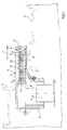
- this cooling grate belongs to a grate cooler, in particular a moving grate cooler, which is used for cooling hot goods, such as hot cement clinker coming from an upstream furnace is determined, the material to be cooled being longitudinal, i.e. is transported in the direction of arrow 1 over the cooling grate.
- This cooling grate contains, in a manner known per se, a multiplicity of rows of grate plates 2 which adjoin one another in the longitudinal direction and overlap.
- the grate plates of each row which are adjacent to one another in the grate transverse direction are each fastened to a grate plate support 3 which runs transversely to the grate, in FIG. 1 only one of these grate plate supports 3 is illustrated.
- This grate plate carrier 3 is designed as a hollow body and for the supply of cooling gas (arrows 4) from below and with a cooling gas chamber or source not shown in detail connected, as cooling gas - as known per se - cooling air can be used.
- Each grate plate 2 has an airfoil 5, through which the material to be cooled is transported along.
- each pocket-shaped depression 6 is worked into the supporting surface 5 of each grate plate 2, which is at least one relative to its base 7 has large, free, window-like through hole 8.
- two pocket-shaped depressions 6 are preferably provided in the grate plate 2 or its supporting surface 5.
- a strip-shaped ventilation cap 9 is also fitted and arranged in each recess 6 in such a way that cooling gas through-openings 10 opening out towards the top of the wings 5 are in the form of essentially closed annular gaps, i.e. these annular gap-shaped cooling gas through openings 10 are delimited on the one hand by the approximately upright inner sides 6a of the pocket-shaped recesses 6 and on the other hand by the outer peripheral edge 9a of the ventilation cover caps 9.
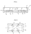
- each ventilation cap 9 It is also important that between the bottom edge area 9b of each ventilation cap 9 and the edge area 7a of the recess bottom 7 opposite this edge area there is formed an essentially annular cooling gas inlet slot 11, the clear width of which is appropriately distributed by the arrangement of several arranged Distance elements 12 can be determined.
- These spacer elements 12 are preferably attached in one piece in a corresponding distribution on the underside of each ventilation cap 9, as indicated in FIG. 5.
- each wing recess 6 on its central section covered by the associated ventilation cap 9 opposite its remaining peripheral edge surface that is to say those under the associated annular-gap-shaped cooling gas Passage opening 10 lying edge area is increased.
- the peripheral edge region 7a of the base 7 already mentioned above is formed on this raised central base section, preferably in such a way that - viewed in the cross section of the grate plate 2 - it slants outward-downward in the direction of the lower section of the associated annular-gap-shaped cooling gas Passage opening 10 has.
- the lower or lower edge region 9b of the associated ventilation cap 9 is also inclined obliquely outwards and downwards over the entire circumference.
- the cooling gas passage slot 11 formed between these two circumferential edge regions 7a and 9b, which are at a distance from one another and viewed in vertical section through the grate plate 2 is also inclined downward in the cooling gas entry direction (arrows 4 in FIG. 1), specifically in the way that it opens over its entire circumference in the lower section of the associated annular gap-shaped cooling gas passage opening 10 (see. Fig. 1 and 2).
- This design and arrangement of the cooling gas inlet slots 11 (in cooperation with the cooling gas through openings 10 and a corresponding cooling gas speed) can be reliably prevented that no fine portions of the good to be cooled can fall down through the grate plate 2 or its cooling gas passage openings 10.
- the ventilation cover caps 9 all have a substantially flat upper side.
- the arrangement of the raised middle section of the floor 7 and the ventilation cover cap 9 is such that the top side 9c of the cover cap 9 is opposite the top plane 5a of the wing 5 is lowered by the dimension A (Fig.2).
- a ventilation pocket 16 is also formed in the area above the ventilation cover cap 9, which can fill with material during the cooling operation of the cooling grate or grate cooler and can thereby particularly advantageously protect this area of the grate plate 2 or airfoil 5 against wear.
- a further advantage of these ventilation pockets 16 during cooling operation is that the cooling gas emerging from the annular gaps 19 in these ventilation pockets above the cover caps 9 form a kind of fluidized bed of the goods stored therein, which then enters a relatively large area into the refrigerated goods bed above it and thus one optimal cooling of the goods favors.
- the cooling gas through openings 10 delimited by the depressions 6 and the ventilation cover caps 9 could have any suitable elongated annular gap shape running in the direction of the goods to be conveyed (arrow 10), insofar as this allows the largest possible cooling gas passage or exit from the grate plate 2 in the refrigerated goods bed is guaranteed.
- the depressions 6 and the ventilation cover caps 9 inserted therein have an elongated rectangular shape in such a way that the annular gaps forming the cooling gas passage openings 10 have a top view have an elongated rectangular shape closed on the wing 5 (cf. FIG. 3), the long sides of the rectangle running essentially parallel to the conveying direction (arrow 1) of the goods to be cooled.
- each grate plate 2 What the number of recesses 6 with associated ventilation caps 9 in each wing 5 or Regarding grate plate 2, this number generally depends on the respective plate size (base area); With the grate plate sizes that have been customary in practice up to now, it has proven to be particularly advantageous to provide in each grate plate 2 only two recesses 6 / ventilation cover caps 9 that are matched to the supporting surface 5 and thus two correspondingly large, circular-gap-shaped cooling gas passage openings 10. In this context, it should also be mentioned that - as can also be seen in FIGS.
- the depressions 6 with their ventilation cover caps 9 can only be arranged in the larger longitudinal section of the grate plate 2, which is in the front in the direction of material conveyance (arrow 1) the reciprocating pushing movement of the rows of grate plates is not brushed by the grate plates 2 lying above them (cf. illustration in FIG. 1).
- the grate plate 2 'or its supporting surface 5' has two evenly distributed cooling gas or cooling air passage openings 10 'on its front longitudinal section pointing in the direction of material conveyance (arrow 1), which openings 10' face towards the top of the Open wing 5 'open and are again in the form of substantially closed annular gaps.
- two such cooling gas passage openings 10 'in the form of an annular gap are correspondingly evenly distributed with an adapted size and elongated rectangular shape and are adapted to the area size.
- annular-gap-shaped cooling gas through openings 10 ' are also formed by incorporating two pocket-shaped recesses 6' from above into the support surface 5 'of the grate plate 2', which have a plurality of through holes 8 'on their base 7' and into each of them a strip-shaped ventilation cap 9 'are fitted and arranged to form the said annular gap.
- each ventilation cap 9 ' has a flat upper side which is flush with the upper side of the wing 5' (see FIG. 7).
- FIGS. 6 and 7 show an embodiment according to which the flow direction (arrow 1) of the longitudinal sections of the rectangular, annular-gap-shaped cooling gas passage openings 10 ', which run to be cooled, are inclined to the vertical, ie All longitudinal sections of the annular-gap-shaped cooling gas passage openings 10 'of a grate plate 2' are inclined in one direction at approximately the same angle to the vertical (cf. cross section in FIG. 7).
- FIG. 8 also shows a partial cross-sectional view of a grate plate carrier 3 ′, again designed as a hollow body, which is designed for the supply of cooling gas from below and on its top side a series of grate plates placed next to one another in the transverse direction - for example in the embodiment according to FIGS 7 - carries.
- the grate plates 2 '(or 2) can be designed and fastened on the grate plate supports 3' (or 3) in such a way that at least the bottom 7 '(or 7) of the Recesses 6 '(or 6) and the ventilation cap 9' (or 9) arranged above them can be flowed freely from below by the cooling gas (dashed arrows 4).
- grate plates 2 'of the type described with reference to FIGS. 6 and 7 are fastened to the grate plate support 3' there, it is preferred to arrange these grate plates 2 'in such a way that - in cross section of the cooling grate viewed and in each case starting from the vertical longitudinal center plane 17 - the longitudinal sections of the cooling gas passage openings 10 'located on the two transverse halves of this cooling grate are each inclined toward the closest outer longitudinal side of the cooling grate.
- the cooling gas emerging from the cooling gas passage openings 10 'upward can to a large extent in the transverse direction to the material conveying direction (arrow 1 in FIG. 3 or perpendicular to the plane of the drawing in FIG. 8) enter the goods to be cooled.
- a kind of tripartite division of the cooling gas duct can be brought about, namely on the one hand a relatively high gas speed (for example about 40 m / s) in the area of the cooling gas inlet slots 11, on the other hand a gas speed which is correspondingly reduced by the larger opening cross section (approximately in the range from 12 to 15 m / s) in the area of the annular gap-shaped cooling gas through openings 10 and thirdly by one in the area of the Ventilation pockets 16 very greatly reduced gas speed, which is only a few m / s (possibly only slightly greater than 0).
- This three-stage cooling gas guide ensures that the wing sections coming into contact with hot material are each Grate plate 2 are adequately cooled, prevents fine parts from penetrating into the cooling gas inlet slots and optimal distribution of the cooling gas escaping upwards in the goods to be cooled (bed) and thus an optimal, very intensive cooling effect is achieved.
- each of these grate plates 22 is essentially flat and has no special ventilation pocket (see. Ventilation pocket 16 in FIG. 2), ie in the case of these grate plates 22 each essentially flat upper side of the ventilation cover cap 9 flush with the top of the wing 5 (About the same as described with reference to Figure 7 of the second embodiment).
- FIGS. 10, 11 and 12 also starts from the basic construction of the first exemplary embodiment described with reference to FIGS. 1 to 5, so that here, too, the same grate plate parts are provided with the same reference numerals. It can be seen in particular from FIGS. 11 and 12 that here, too, two equally sized pocket-shaped depressions 6 are formed in the supporting surface of each of the grate plates 32 shown here, into each of which a strip-shaped ventilation cover cap 9 is fitted and arranged on the bottom 7 is that there is a cooling gas passage opening 10 in the form of a closed annular gap.
- each ventilation cap 9 is additionally lowered by a suitable dimension A with respect to the upper side 5a of the wing 5 with the additional formation of a ventilation pocket 16 (similar to the first exemplary embodiment in FIGS. 1 to 5).
- each recess 6 is primarily composed of two longitudinal webs which are arranged at a distance from one another and parallel to one another and to the material conveying direction (arrow 1), namely the webs 33, 34 on the one hand and the webs 34 and 35 on the other hand, as well as a front end web 36, viewed in the conveying direction (arrow 1), which runs across the entire grate plate 32.
- the material conveying direction arrow 1
- the 10 to 12 differs primarily in that, in addition to the front web 36, only the two outer longitudinal webs 33 and 35 extend to the height of the wing top 5a while forming an approximately box-shaped common ventilation pocket 16 the upper edge 34a of the central longitudinal web 34 lies approximately at the level of the upper sides 9c of the two ventilation cover caps 9.
- the height of the central longitudinal web 34 is reduced compared to the other longitudinal webs 35, 36.
- the embodiment variant of grate plates 42 illustrated with reference to FIGS. 13 and 14 also deals with the formation of the ventilation pockets 16 in the area above the ventilation cover caps 9.
- only the front end web 36 extends to form the ventilation pocket 16 up to the height of the wing top 5a.
- all longitudinal webs 33, 34 and 35 extending in the direction of material conveyance (arrow 1) are only guided up to the height of the upper sides 9c of the ventilation cover caps 9, ie their upper edges lie approximately in the same plane as the upper sides of these ventilation cover caps 9.
- the ventilation pocket In this embodiment variant 16 is therefore mainly limited by the front end web 36 and of course also by the rear part (see wing 5) of these grate plates 42, as viewed in the direction of good conveyance (arrow 1), as can be seen from FIG. 13 .
Landscapes
- Engineering & Computer Science (AREA)
- Mechanical Engineering (AREA)
- General Engineering & Computer Science (AREA)
- Furnace Details (AREA)
- Baking, Grill, Roasting (AREA)
- Curing Cements, Concrete, And Artificial Stone (AREA)
Claims (16)
- Grille de refroidissement d'un réfrigérant de matière chaude, comprenant de multiples plaques de grille (2, 2') fixées sur des supports (3, 3') perpendiculaires à la grille et dont chacune comporte une surface porteuse (5, 5') destinée à une matière à refroidir qui est transportée sur la grille de refroidissement, des orifices de passage de gaz de refroidissement (10, 10') qui débouchent dans les surfaces porteuses vers leur côté supérieur étant prévus, caractérisée en ce qu'au moins une cavité en forme de poche (6, 6') usinée par le haut dans la surface porteuse (5, 5') de chaque plaque de grille (2, 2') comporte au moins un trou de traversée (8, 8') dans le fond (7, 7') et un chapeau de ventilation (9, 9') en forme de barre est ajusté et disposé dans la cavité de manière à réaliser un orifice de passage du gaz de refroidissement (10, 10') ayant la forme d'un intervalle annulaire sensiblement fermé.
- Grille de refroidissement selon la revendication 1, caractérisée en ce qu'une fente circonférentielle sensiblement annulaire (11, 11') d'entrée du gaz de refroidissement, dont la largeur intérieure peut être déterminée par la disposition d'entretoises (12), est réalisée entre la région du bord (9b) du côté inférieur de chaque chapeau de ventilation (9, 9') et la région opposée du bord (7a) du fond (7, 7') de chaque cavité (6, 6').
- Grille de refroidissement selon la revendication 2, caractérisée en ce que la partie centrale du fond (7) de chaque cavité (6) de la surface porteuse qui est recouverte par le chapeau correspondant de ventilation (9) est surélevée par rapport au reste de sa surface circonférentielle et en ce que la fente (11, 11') d'entrée du gaz de refroidissement - en vue en coupe transversale de la plaque de la grille - est inclinée vers le bas dans le sens (4) d'entrée du gaz de refroidissement et débouche dans la partie inférieure de l'orifice correspondant (10, 10') en forme d'intervalle annulaire de passage du gaz de refroidissement.
- Grille de refroidissement selon la revendication 3, caractérisée en ce que le côté inférieur de chaque chapeau de ventilation (9) comporte plusieurs goujons (15) saillants vers le bas qui sont enfilés dans des trous (14) de la partie surélevée du fond de la cavité correspondante pour la fixation de ce chapeau sur le fond (7) de la cavité.
- Grille de refroidissement selon la revendication 1, caractérisée en ce que chaque chapeau de ventilation (9) présente un côté supérieur sensiblement plan (9c) qui, lorsqu'une poche de ventilation (16) est accessoirement réalisée dans la cavité correspondante (6), est situé plus bas que le côté supérieur (5a) de la surface porteuse (5).
- Grille de refroidissement selon la revendication 5, caractérisée en ce que chaque cavité (6) est délimitée par deux longerons (33, 34, 35) placés à distance l'un de l'autre et parallèles l'un à l'autre et au sens (1) de transport de la matière, ainsi que par une traverse antérieure frontale (36) - observée par rapport au sens de transport de la matière (1) -, au moins l'une de ces traverses antérieures (36) se prolongeant jusqu'au niveau du côté supérieur (5a) de la surface porteuse pour la formation de la poche de ventilation (16).
- Grille de refroidissement selon la revendication 6, caractérisée en ce que, lorsqu'au moins deux cavités (6) sont usinées dans chaque plaque de grille (32), les deux longerons extérieurs (33, 35) se prolongent également jusqu'au niveau du côté supérieur (5a) de la surface porteuse afin de réaliser une poche commune de ventilation (16) approximativement en forme de caisson.
- Grille de refroidissement selon la revendication 6, caractérisée en ce que, lorsqu'au moins deux cavités sont usinées dans chaque plaque de grille (42), les deux longerons extérieurs (33, 35) ainsi que le longeron médian (34) se prolongent au-dessus de chaque cavité (6) jusqu'au niveau du côté supérieur (5a) de la surface porteuse, de manière à former dans chaque cas une poche de ventilation (16) approximativement en forme de caisson.
- Grille de refroidissement selon la revendication 6, caractérisée en ce que seul celui des deux longerons extérieurs (33, 35) qui est voisin d'un côté longitudinal extérieur de la grille de refroidissement se prolonge également jusqu'au niveau du côté supérieur (5a) de la surface porteuse.
- Grille de refroidissement selon la revendication 1, caractérisée en ce que chaque chapeau de ventilation (9, 9' des figures 7 et 9) comporte un côté supérieur sensiblement plan qui est à fleur du côté supérieur de la surface porteuse (5, 5' des figures 7 et 9).
- Grille de refroidissement selon la revendication 1, caractérisée en ce que les intervalles annulaires formant les orifices de passage du gaz de refroidissement (10, 10') ont une forme rectangulaire allongée et fermée en vue en plan de la surface porteuse (5, 5'), les côtés longs des rectangles étant sensiblement parallèles au sens (1) de transport de la matière à refroidir.
- Grille de refroidissement selon la revendication 1, caractérisée en ce qu'au moins deux cavités (6, 6') ainsi qu'au moins un chapeau de ventilation (9, 9') affecté à chacune de celles-ci sont prévus dans la surface porteuse (5, 5') de chaque plaque de grille (2, 2').
- Grille de refroidissement selon la revendication 2, les supports (3, 3') de la plaque de grille étant conformés en corps creux et pour l'arrivée du gaz de refroidissement, caractérisée en ce que les plaques de grille (2, 2') sont réalisées et fixées sur les supports (3, 3') de manière qu'au moins le fond (7, 7') des cavités (6, 6') et les chapeaux de ventilation (9, 9') placés sur ces fonds puissent être librement balayés par le gaz de refroidissement (4).
- Grille de refroidissement selon la revendication 13, caractérisée en ce que l'ouverture intérieure de la fente (11, 11') d'entrée du gaz de refroidissement est adoptée de manière que des quantités à peu près égales de gaz de refroidissement puissent être dirigées sur les plaques de grille (2, 2') balayées par du gaz de refroidissement à travers une partie de leur support.
- Grille de refroidissement selon la revendication 13, caractérisée en ce que les orifices (10) en forme d'intervalles annulaires de passage du gaz de refroidissement sont orientés sensiblement perpendiculairement au côté supérieur (5a) des surfaces porteuses (5).
- Grille de refroidissement selon la revendication 13, caractérisée en ce que les parties longitudinales, orientées dans le sens (1) du transport de la matière à refroidir, des orifices (10') en forme d'intervalles annulaires de passage du gaz de refroidissement sont inclinées sur la verticale, les parties longitudinales - vues en coupe transversale de la grille de refroidissement et dans chaque cas à partir du plan longitudinal vertical de symétrie (17) - des orifices (10') de passage de gaz de refroidissement des plaques de grille (2') fixées sur les deux moitiés transversales de la grille de refroidissement étant inclinées vers le côté longitudinal extérieur voisin de la grille de refroidissement.
Applications Claiming Priority (2)
| Application Number | Priority Date | Filing Date | Title |
|---|---|---|---|
| DE4134242A DE4134242A1 (de) | 1991-10-16 | 1991-10-16 | Kuehlrost |
| DE4134242 | 1991-10-16 |
Publications (2)
| Publication Number | Publication Date |
|---|---|
| EP0537523A1 EP0537523A1 (fr) | 1993-04-21 |
| EP0537523B1 true EP0537523B1 (fr) | 1994-12-14 |
Family
ID=6442805
Family Applications (1)
| Application Number | Title | Priority Date | Filing Date |
|---|---|---|---|
| EP92116376A Expired - Lifetime EP0537523B1 (fr) | 1991-10-16 | 1992-09-24 | Refroidisseur à grilles |
Country Status (6)
| Country | Link |
|---|---|
| US (1) | US5322434A (fr) |
| EP (1) | EP0537523B1 (fr) |
| DE (2) | DE4134242A1 (fr) |
| DK (1) | DK0537523T3 (fr) |
| ES (1) | ES2067283T3 (fr) |
| ZA (1) | ZA927452B (fr) |
Cited By (6)
| Publication number | Priority date | Publication date | Assignee | Title |
|---|---|---|---|---|
| TR24997A (tr) * | 1989-10-11 | 1992-09-01 | Henkel Kgaa | ALKIL-POLIETOKSIETER SüLFAT LARIN üRETILMESINE MAHSUS USUL |
| WO1994008191A1 (fr) * | 1992-10-06 | 1994-04-14 | F.L. Smidth & Co A/S | Element de grille |
| EP0634619A1 (fr) * | 1993-07-15 | 1995-01-18 | Klöckner-Humboldt-Deutz Aktiengesellschaft | Plaque de grille pour refroidisseur à plaques mobiles |
| US5713345A (en) * | 1992-10-06 | 1998-02-03 | F. L. Smidth & Co. A/S | Grate element |
| US5836758A (en) * | 1996-01-25 | 1998-11-17 | Krupp Polysius Ag | Reciprocating grate for the treatment of bulk material |
| US5882189A (en) * | 1994-10-31 | 1999-03-16 | Babcock Materials Handling Division Gmbh | Sliding grate for a burnt-material-cooling unit, and grating plate therefor |
Families Citing this family (17)
| Publication number | Priority date | Publication date | Assignee | Title |
|---|---|---|---|---|
| DE4412885A1 (de) * | 1994-04-14 | 1995-10-19 | Krupp Polysius Ag | Kühlrost |
| DE9417829U1 (de) | 1994-11-07 | 1996-03-14 | Babcock Materials Handling Division GmbH, 21614 Buxtehude | Rostplatte für den Schubrost eines Kühlers |
| DE19504311A1 (de) * | 1995-02-09 | 1996-08-14 | Krupp Polysius Ag | Zweischichtkühler |
| DE19504588B4 (de) * | 1995-02-11 | 2006-07-13 | Khd Humboldt Wedag Gmbh | Rostplatte für Schubrostkühler zum Abkühlen von heißem Gut |
| CH689519A5 (de) * | 1995-05-17 | 1999-05-31 | Von Roll Umwelttechnik Ag | Gekuehlter Rostblock. |
| DE19537904A1 (de) * | 1995-06-28 | 1997-01-02 | Krupp Polysius Ag | Rostplatte |
| US5575642A (en) * | 1995-12-01 | 1996-11-19 | The Carondelet Corporation | Grate plate |
| ZA969708B (en) * | 1995-12-15 | 1997-06-20 | Krupp Polysius Ag | Prevention of snowmen and removal of lumps in clinker coolers |
| TW457354B (en) * | 1999-08-20 | 2001-10-01 | Von Roll Umwelttechnik Ag | Plant and grate block for the thermal treatment of waste materials |
| US7093457B2 (en) * | 2004-01-23 | 2006-08-22 | Metso Minerals Industries, Inc. | Annular cooler pallet construction |
| DE102004040048A1 (de) * | 2004-08-18 | 2006-02-23 | Ikn Gmbh | Rostplattenanordnung für Stufenroste |
| DE102008053893B4 (de) * | 2008-10-30 | 2010-08-19 | Audi Ag | Vorrichtung und Verfahren zum Kühlen wenigstens eines Gussbauteils |
| DE102009009285B4 (de) * | 2009-02-17 | 2013-11-28 | Ikn Gmbh | Rostplattenanordnung |
| US8616292B2 (en) * | 2010-03-19 | 2013-12-31 | Halliburton Energy Services, Inc. | Resettable downhole torque limiter and related methods of use |
| CN104211425B (zh) | 2013-06-04 | 2015-12-02 | 四川玖长科技有限公司 | 窑法磷酸工艺中出回转窑高温渣球的综合利用方法及其工艺系统 |
| CN104211030B (zh) | 2013-06-04 | 2016-03-09 | 四川玖长科技有限公司 | 改进型的用回转窑规模化生产磷酸的方法 |
| DE102015015632B4 (de) * | 2015-12-03 | 2017-12-07 | Khd Humboldt Wedag Gmbh | Rostplatte für einen Rostkühler |
Family Cites Families (11)
| Publication number | Priority date | Publication date | Assignee | Title |
|---|---|---|---|---|
| US1910233A (en) * | 1930-07-15 | 1933-05-23 | Frank M Blair | Apparatus for burning solid carbonizable fuels |
| FR784409A (fr) * | 1934-04-11 | 1935-07-22 | Dispositif amovible pour l'amélioration de la combustion des combustibles solides dans les foyers | |
| US2112420A (en) * | 1935-06-18 | 1938-03-29 | Iron Fireman Mfg Co | Ash remover |
| US2320410A (en) * | 1940-06-19 | 1943-06-01 | Thomas C Cheasley | Combination retort and hearth for stokers |
| DE2011518B2 (de) * | 1970-03-11 | 1972-06-08 | Wedag Westfalia Dinnendahl Gröppel AG, 4630 Bochum | Rostplatte fuer rostkuehler |
| DE2808057C2 (de) * | 1978-02-24 | 1980-02-14 | Josef Martin Feuerungsbau Gmbh, 8000 Muenchen | Rostbelag für mechanisch bewegte stufenförmige Feuerungsroste von Großfeuerungen |
| DE3332592C1 (de) * | 1983-09-08 | 1985-05-15 | Karl von Dipl.-Ing. Dipl.-Wirtsch.-Ing. 3057 Neustadt Wedel | Aus Rostelementen zusammengesetzter Rostboden fuer Schuettgueter,wie Zementklinker |
| DE3616630A1 (de) * | 1986-05-16 | 1987-11-19 | Krupp Polysius Ag | Kuehlvorrichtung |
| DE3734043A1 (de) * | 1987-10-08 | 1989-04-20 | Kloeckner Humboldt Deutz Ag | Rostkuehler zum kuehlen von heissem schuettgut |
| DE3812425A1 (de) * | 1988-04-14 | 1989-10-26 | Peters Ag Claudius | Kuehlerrostplatte |
| US5174747A (en) * | 1991-09-03 | 1992-12-29 | Fuller Company | Grate plate |
-
1991
- 1991-10-16 DE DE4134242A patent/DE4134242A1/de not_active Withdrawn
-
1992
- 1992-09-24 DE DE59200975T patent/DE59200975D1/de not_active Expired - Fee Related
- 1992-09-24 DK DK92116376.2T patent/DK0537523T3/da active
- 1992-09-24 ES ES92116376T patent/ES2067283T3/es not_active Expired - Lifetime
- 1992-09-24 EP EP92116376A patent/EP0537523B1/fr not_active Expired - Lifetime
- 1992-09-29 ZA ZA927452A patent/ZA927452B/xx unknown
- 1992-10-05 US US07/956,809 patent/US5322434A/en not_active Expired - Fee Related
Cited By (7)
| Publication number | Priority date | Publication date | Assignee | Title |
|---|---|---|---|---|
| TR24997A (tr) * | 1989-10-11 | 1992-09-01 | Henkel Kgaa | ALKIL-POLIETOKSIETER SüLFAT LARIN üRETILMESINE MAHSUS USUL |
| WO1994008191A1 (fr) * | 1992-10-06 | 1994-04-14 | F.L. Smidth & Co A/S | Element de grille |
| TR27307A (tr) * | 1992-10-06 | 1994-12-29 | Smidth & Co As F L | Bir izgara yüzeyine mahsus mesela bir curuf sogutucusunda kullanilan izgara elemani. |
| US5713345A (en) * | 1992-10-06 | 1998-02-03 | F. L. Smidth & Co. A/S | Grate element |
| EP0634619A1 (fr) * | 1993-07-15 | 1995-01-18 | Klöckner-Humboldt-Deutz Aktiengesellschaft | Plaque de grille pour refroidisseur à plaques mobiles |
| US5882189A (en) * | 1994-10-31 | 1999-03-16 | Babcock Materials Handling Division Gmbh | Sliding grate for a burnt-material-cooling unit, and grating plate therefor |
| US5836758A (en) * | 1996-01-25 | 1998-11-17 | Krupp Polysius Ag | Reciprocating grate for the treatment of bulk material |
Also Published As
| Publication number | Publication date |
|---|---|
| ZA927452B (en) | 1993-04-07 |
| US5322434A (en) | 1994-06-21 |
| DE4134242A1 (de) | 1993-04-22 |
| EP0537523A1 (fr) | 1993-04-21 |
| DE59200975D1 (de) | 1995-01-26 |
| DK0537523T3 (da) | 1995-05-15 |
| ES2067283T3 (es) | 1995-03-16 |
Similar Documents
| Publication | Publication Date | Title |
|---|---|---|
| EP0537523B1 (fr) | Refroidisseur à grilles | |
| DE10018142B4 (de) | Kühler und Verfahren zum Kühlen von heißem Schüttgut | |
| DE69727455T2 (de) | Linearführungvorrichtung mit mehreren kugelkettenreihen | |
| EP0811818B2 (fr) | Plaque de grille et procédé pour sa fabrication | |
| EP0677714B1 (fr) | Refroidisseur à grilles poussantes | |
| DD232539B5 (de) | Rostbodenelement zum Aufbau einer Rostflaeche | |
| DE3505256C2 (de) | Vorrichtung zum berührungsfreien Führen von Warenbahnen, insbesondere Metallbändern, mittels eines Gasmediums | |
| DE19713268B4 (de) | Gekühlte Gasturbinenschaufel | |
| DE3304783C2 (fr) | ||
| DE4105330C1 (fr) | ||
| EP0337383B1 (fr) | Plaque de grille de refroidisseur | |
| DE9321344U1 (de) | Förderbandmatte | |
| DE2610691C3 (de) | Vorrichtung zum Führen der Stoffsuspension in einem Stoffauflauf einer Papiermaschine | |
| EP0396908B1 (fr) | Barreau de grille et grille à rouleaux | |
| DE3419450C2 (fr) | ||
| DE69405018T2 (de) | Hubbalkenofen für die beschleunigte Heizung von Knuppeln und dergleichen | |
| DE19537904A1 (de) | Rostplatte | |
| EP0979985B1 (fr) | Dispositif pour le traitement thermique d'une bande de matière textile | |
| EP0741811B1 (fr) | Module a outils de tufting | |
| DE19708455B4 (de) | Transportmatte | |
| DE2809927A1 (de) | Schachtkuehler | |
| DE3411814C2 (de) | Anlage zum Herstellen von geformten Schokoladen-Artikeln | |
| DE4205534A1 (de) | Rostplatte fuer schubrostkuehler zum abkuehlen von heissem gut | |
| EP3023694A1 (fr) | Barreau de grille et grille pour un foyer a grille | |
| DE10117225A1 (de) | Kühlrost für einen Schüttgutkühler |
Legal Events
| Date | Code | Title | Description |
|---|---|---|---|
| PUAI | Public reference made under article 153(3) epc to a published international application that has entered the european phase |
Free format text: ORIGINAL CODE: 0009012 |
|
| AK | Designated contracting states |
Kind code of ref document: A1 Designated state(s): BE DE DK ES FR GB IT |
|
| 17P | Request for examination filed |
Effective date: 19930503 |
|
| 17Q | First examination report despatched |
Effective date: 19940222 |
|
| GRAA | (expected) grant |
Free format text: ORIGINAL CODE: 0009210 |
|
| AK | Designated contracting states |
Kind code of ref document: B1 Designated state(s): BE DE DK ES FR GB IT |
|
| REF | Corresponds to: |
Ref document number: 59200975 Country of ref document: DE Date of ref document: 19950126 |
|
| ITF | It: translation for a ep patent filed | ||
| GBT | Gb: translation of ep patent filed (gb section 77(6)(a)/1977) |
Effective date: 19950215 |
|
| REG | Reference to a national code |
Ref country code: ES Ref legal event code: FG2A Ref document number: 2067283 Country of ref document: ES Kind code of ref document: T3 |
|
| ET | Fr: translation filed | ||
| REG | Reference to a national code |
Ref country code: DK Ref legal event code: T3 |
|
| PLBI | Opposition filed |
Free format text: ORIGINAL CODE: 0009260 |
|
| PLBI | Opposition filed |
Free format text: ORIGINAL CODE: 0009260 |
|
| 26 | Opposition filed |
Opponent name: FIRMA BABCOCK MATERIALS HANDLING AG Effective date: 19950908 |
|
| 26 | Opposition filed |
Opponent name: KLOECKNER-HUMBOLDT-DEUTZ AG PATENTE, MARKEN UND LI Effective date: 19950912 Opponent name: FIRMA BABCOCK MATERIALS HANDLING AG Effective date: 19950908 |
|
| PLBF | Reply of patent proprietor to notice(s) of opposition |
Free format text: ORIGINAL CODE: EPIDOS OBSO |
|
| PLBO | Opposition rejected |
Free format text: ORIGINAL CODE: EPIDOS REJO |
|
| PLBN | Opposition rejected |
Free format text: ORIGINAL CODE: 0009273 |
|
| 27O | Opposition rejected |
Effective date: 19960907 |
|
| PGFP | Annual fee paid to national office [announced via postgrant information from national office to epo] |
Ref country code: FR Payment date: 19970811 Year of fee payment: 6 |
|
| PGFP | Annual fee paid to national office [announced via postgrant information from national office to epo] |
Ref country code: DK Payment date: 19970812 Year of fee payment: 6 |
|
| PGFP | Annual fee paid to national office [announced via postgrant information from national office to epo] |
Ref country code: GB Payment date: 19970815 Year of fee payment: 6 |
|
| PGFP | Annual fee paid to national office [announced via postgrant information from national office to epo] |
Ref country code: BE Payment date: 19970822 Year of fee payment: 6 |
|
| PGFP | Annual fee paid to national office [announced via postgrant information from national office to epo] |
Ref country code: ES Payment date: 19970915 Year of fee payment: 6 |
|
| PGFP | Annual fee paid to national office [announced via postgrant information from national office to epo] |
Ref country code: DE Payment date: 19970930 Year of fee payment: 6 |
|
| PG25 | Lapsed in a contracting state [announced via postgrant information from national office to epo] |
Ref country code: GB Free format text: LAPSE BECAUSE OF NON-PAYMENT OF DUE FEES Effective date: 19980924 Ref country code: DK Free format text: LAPSE BECAUSE OF NON-PAYMENT OF DUE FEES Effective date: 19980924 |
|
| PG25 | Lapsed in a contracting state [announced via postgrant information from national office to epo] |
Ref country code: ES Free format text: LAPSE BECAUSE OF NON-PAYMENT OF DUE FEES Effective date: 19980925 |
|
| PG25 | Lapsed in a contracting state [announced via postgrant information from national office to epo] |
Ref country code: BE Free format text: LAPSE BECAUSE OF NON-PAYMENT OF DUE FEES Effective date: 19980930 |
|
| BERE | Be: lapsed |
Owner name: KRUPP POLYSIUS A.G. Effective date: 19980930 |
|
| GBPC | Gb: european patent ceased through non-payment of renewal fee |
Effective date: 19980924 |
|
| PG25 | Lapsed in a contracting state [announced via postgrant information from national office to epo] |
Ref country code: FR Free format text: LAPSE BECAUSE OF NON-PAYMENT OF DUE FEES Effective date: 19990531 |
|
| PG25 | Lapsed in a contracting state [announced via postgrant information from national office to epo] |
Ref country code: DE Free format text: LAPSE BECAUSE OF NON-PAYMENT OF DUE FEES Effective date: 19990701 |
|
| REG | Reference to a national code |
Ref country code: FR Ref legal event code: ST |
|
| REG | Reference to a national code |
Ref country code: DK Ref legal event code: EBP |
|
| REG | Reference to a national code |
Ref country code: ES Ref legal event code: FD2A Effective date: 19991013 |
|
| PG25 | Lapsed in a contracting state [announced via postgrant information from national office to epo] |
Ref country code: IT Free format text: LAPSE BECAUSE OF NON-PAYMENT OF DUE FEES Effective date: 20050924 |