EP0537647A2 - Installation d'extrusion avec dispositif de mesure de l'épaisseur pour tuyau extrudé - Google Patents
Installation d'extrusion avec dispositif de mesure de l'épaisseur pour tuyau extrudé Download PDFInfo
- Publication number
- EP0537647A2 EP0537647A2 EP92117343A EP92117343A EP0537647A2 EP 0537647 A2 EP0537647 A2 EP 0537647A2 EP 92117343 A EP92117343 A EP 92117343A EP 92117343 A EP92117343 A EP 92117343A EP 0537647 A2 EP0537647 A2 EP 0537647A2
- Authority
- EP
- European Patent Office
- Prior art keywords
- measuring
- calibration sleeve
- chamber
- wall thickness
- extrusion system
- Prior art date
- Legal status (The legal status is an assumption and is not a legal conclusion. Google has not performed a legal analysis and makes no representation as to the accuracy of the status listed.)
- Ceased
Links
Images



Classifications
-
- G—PHYSICS
- G01—MEASURING; TESTING
- G01B—MEASURING LENGTH, THICKNESS OR SIMILAR LINEAR DIMENSIONS; MEASURING ANGLES; MEASURING AREAS; MEASURING IRREGULARITIES OF SURFACES OR CONTOURS
- G01B21/00—Measuring arrangements or details thereof, where the measuring technique is not covered by the other groups of this subclass, unspecified or not relevant
- G01B21/02—Measuring arrangements or details thereof, where the measuring technique is not covered by the other groups of this subclass, unspecified or not relevant for measuring length, width, or thickness
- G01B21/08—Measuring arrangements or details thereof, where the measuring technique is not covered by the other groups of this subclass, unspecified or not relevant for measuring length, width, or thickness for measuring thickness
-
- B—PERFORMING OPERATIONS; TRANSPORTING
- B29—WORKING OF PLASTICS; WORKING OF SUBSTANCES IN A PLASTIC STATE IN GENERAL
- B29C—SHAPING OR JOINING OF PLASTICS; SHAPING OF MATERIAL IN A PLASTIC STATE, NOT OTHERWISE PROVIDED FOR; AFTER-TREATMENT OF THE SHAPED PRODUCTS, e.g. REPAIRING
- B29C48/00—Extrusion moulding, i.e. expressing the moulding material through a die or nozzle which imparts the desired form; Apparatus therefor
- B29C48/03—Extrusion moulding, i.e. expressing the moulding material through a die or nozzle which imparts the desired form; Apparatus therefor characterised by the shape of the extruded material at extrusion
- B29C48/09—Articles with cross-sections having partially or fully enclosed cavities, e.g. pipes or channels
-
- B—PERFORMING OPERATIONS; TRANSPORTING
- B29—WORKING OF PLASTICS; WORKING OF SUBSTANCES IN A PLASTIC STATE IN GENERAL
- B29C—SHAPING OR JOINING OF PLASTICS; SHAPING OF MATERIAL IN A PLASTIC STATE, NOT OTHERWISE PROVIDED FOR; AFTER-TREATMENT OF THE SHAPED PRODUCTS, e.g. REPAIRING
- B29C48/00—Extrusion moulding, i.e. expressing the moulding material through a die or nozzle which imparts the desired form; Apparatus therefor
- B29C48/25—Component parts, details or accessories; Auxiliary operations
- B29C48/88—Thermal treatment of the stream of extruded material, e.g. cooling
- B29C48/90—Thermal treatment of the stream of extruded material, e.g. cooling with calibration or sizing, i.e. combined with fixing or setting of the final dimensions of the extruded article
- B29C48/901—Thermal treatment of the stream of extruded material, e.g. cooling with calibration or sizing, i.e. combined with fixing or setting of the final dimensions of the extruded article of hollow bodies
- B29C48/903—Thermal treatment of the stream of extruded material, e.g. cooling with calibration or sizing, i.e. combined with fixing or setting of the final dimensions of the extruded article of hollow bodies externally
-
- B—PERFORMING OPERATIONS; TRANSPORTING
- B29—WORKING OF PLASTICS; WORKING OF SUBSTANCES IN A PLASTIC STATE IN GENERAL
- B29C—SHAPING OR JOINING OF PLASTICS; SHAPING OF MATERIAL IN A PLASTIC STATE, NOT OTHERWISE PROVIDED FOR; AFTER-TREATMENT OF THE SHAPED PRODUCTS, e.g. REPAIRING
- B29C48/00—Extrusion moulding, i.e. expressing the moulding material through a die or nozzle which imparts the desired form; Apparatus therefor
- B29C48/25—Component parts, details or accessories; Auxiliary operations
- B29C48/92—Measuring, controlling or regulating
-
- G—PHYSICS
- G01—MEASURING; TESTING
- G01B—MEASURING LENGTH, THICKNESS OR SIMILAR LINEAR DIMENSIONS; MEASURING ANGLES; MEASURING AREAS; MEASURING IRREGULARITIES OF SURFACES OR CONTOURS
- G01B5/00—Measuring arrangements characterised by the use of mechanical techniques
- G01B5/0002—Arrangements for supporting, fixing or guiding the measuring instrument or the object to be measured
-
- G—PHYSICS
- G01—MEASURING; TESTING
- G01B—MEASURING LENGTH, THICKNESS OR SIMILAR LINEAR DIMENSIONS; MEASURING ANGLES; MEASURING AREAS; MEASURING IRREGULARITIES OF SURFACES OR CONTOURS
- G01B5/00—Measuring arrangements characterised by the use of mechanical techniques
- G01B5/02—Measuring arrangements characterised by the use of mechanical techniques for measuring length, width or thickness
- G01B5/06—Measuring arrangements characterised by the use of mechanical techniques for measuring length, width or thickness for measuring thickness
- G01B5/068—Measuring arrangements characterised by the use of mechanical techniques for measuring length, width or thickness for measuring thickness of objects while moving
-
- B—PERFORMING OPERATIONS; TRANSPORTING
- B29—WORKING OF PLASTICS; WORKING OF SUBSTANCES IN A PLASTIC STATE IN GENERAL
- B29C—SHAPING OR JOINING OF PLASTICS; SHAPING OF MATERIAL IN A PLASTIC STATE, NOT OTHERWISE PROVIDED FOR; AFTER-TREATMENT OF THE SHAPED PRODUCTS, e.g. REPAIRING
- B29C2948/00—Indexing scheme relating to extrusion moulding
- B29C2948/92—Measuring, controlling or regulating
- B29C2948/92009—Measured parameter
- B29C2948/92114—Dimensions
- B29C2948/92152—Thickness
-
- B—PERFORMING OPERATIONS; TRANSPORTING
- B29—WORKING OF PLASTICS; WORKING OF SUBSTANCES IN A PLASTIC STATE IN GENERAL
- B29C—SHAPING OR JOINING OF PLASTICS; SHAPING OF MATERIAL IN A PLASTIC STATE, NOT OTHERWISE PROVIDED FOR; AFTER-TREATMENT OF THE SHAPED PRODUCTS, e.g. REPAIRING
- B29C2948/00—Indexing scheme relating to extrusion moulding
- B29C2948/92—Measuring, controlling or regulating
- B29C2948/92323—Location or phase of measurement
- B29C2948/92428—Calibration, after-treatment, or cooling zone
-
- B—PERFORMING OPERATIONS; TRANSPORTING
- B29—WORKING OF PLASTICS; WORKING OF SUBSTANCES IN A PLASTIC STATE IN GENERAL
- B29C—SHAPING OR JOINING OF PLASTICS; SHAPING OF MATERIAL IN A PLASTIC STATE, NOT OTHERWISE PROVIDED FOR; AFTER-TREATMENT OF THE SHAPED PRODUCTS, e.g. REPAIRING
- B29C2948/00—Indexing scheme relating to extrusion moulding
- B29C2948/92—Measuring, controlling or regulating
- B29C2948/92504—Controlled parameter
- B29C2948/92571—Position, e.g. linear or angular
-
- B—PERFORMING OPERATIONS; TRANSPORTING
- B29—WORKING OF PLASTICS; WORKING OF SUBSTANCES IN A PLASTIC STATE IN GENERAL
- B29C—SHAPING OR JOINING OF PLASTICS; SHAPING OF MATERIAL IN A PLASTIC STATE, NOT OTHERWISE PROVIDED FOR; AFTER-TREATMENT OF THE SHAPED PRODUCTS, e.g. REPAIRING
- B29C2948/00—Indexing scheme relating to extrusion moulding
- B29C2948/92—Measuring, controlling or regulating
- B29C2948/92819—Location or phase of control
- B29C2948/92923—Calibration, after-treatment or cooling zone
-
- B—PERFORMING OPERATIONS; TRANSPORTING
- B29—WORKING OF PLASTICS; WORKING OF SUBSTANCES IN A PLASTIC STATE IN GENERAL
- B29C—SHAPING OR JOINING OF PLASTICS; SHAPING OF MATERIAL IN A PLASTIC STATE, NOT OTHERWISE PROVIDED FOR; AFTER-TREATMENT OF THE SHAPED PRODUCTS, e.g. REPAIRING
- B29C48/00—Extrusion moulding, i.e. expressing the moulding material through a die or nozzle which imparts the desired form; Apparatus therefor
- B29C48/25—Component parts, details or accessories; Auxiliary operations
- B29C48/88—Thermal treatment of the stream of extruded material, e.g. cooling
- B29C48/885—External treatment, e.g. by using air rings for cooling tubular films
-
- B—PERFORMING OPERATIONS; TRANSPORTING
- B29—WORKING OF PLASTICS; WORKING OF SUBSTANCES IN A PLASTIC STATE IN GENERAL
- B29C—SHAPING OR JOINING OF PLASTICS; SHAPING OF MATERIAL IN A PLASTIC STATE, NOT OTHERWISE PROVIDED FOR; AFTER-TREATMENT OF THE SHAPED PRODUCTS, e.g. REPAIRING
- B29C48/00—Extrusion moulding, i.e. expressing the moulding material through a die or nozzle which imparts the desired form; Apparatus therefor
- B29C48/25—Component parts, details or accessories; Auxiliary operations
- B29C48/88—Thermal treatment of the stream of extruded material, e.g. cooling
- B29C48/90—Thermal treatment of the stream of extruded material, e.g. cooling with calibration or sizing, i.e. combined with fixing or setting of the final dimensions of the extruded article
- B29C48/905—Thermal treatment of the stream of extruded material, e.g. cooling with calibration or sizing, i.e. combined with fixing or setting of the final dimensions of the extruded article using wet calibration, i.e. in a quenching tank
-
- B—PERFORMING OPERATIONS; TRANSPORTING
- B29—WORKING OF PLASTICS; WORKING OF SUBSTANCES IN A PLASTIC STATE IN GENERAL
- B29C—SHAPING OR JOINING OF PLASTICS; SHAPING OF MATERIAL IN A PLASTIC STATE, NOT OTHERWISE PROVIDED FOR; AFTER-TREATMENT OF THE SHAPED PRODUCTS, e.g. REPAIRING
- B29C48/00—Extrusion moulding, i.e. expressing the moulding material through a die or nozzle which imparts the desired form; Apparatus therefor
- B29C48/25—Component parts, details or accessories; Auxiliary operations
- B29C48/88—Thermal treatment of the stream of extruded material, e.g. cooling
- B29C48/90—Thermal treatment of the stream of extruded material, e.g. cooling with calibration or sizing, i.e. combined with fixing or setting of the final dimensions of the extruded article
- B29C48/908—Thermal treatment of the stream of extruded material, e.g. cooling with calibration or sizing, i.e. combined with fixing or setting of the final dimensions of the extruded article characterised by calibrator surface, e.g. structure or holes for lubrication, cooling or venting
-
- B—PERFORMING OPERATIONS; TRANSPORTING
- B29—WORKING OF PLASTICS; WORKING OF SUBSTANCES IN A PLASTIC STATE IN GENERAL
- B29C—SHAPING OR JOINING OF PLASTICS; SHAPING OF MATERIAL IN A PLASTIC STATE, NOT OTHERWISE PROVIDED FOR; AFTER-TREATMENT OF THE SHAPED PRODUCTS, e.g. REPAIRING
- B29C48/00—Extrusion moulding, i.e. expressing the moulding material through a die or nozzle which imparts the desired form; Apparatus therefor
- B29C48/25—Component parts, details or accessories; Auxiliary operations
- B29C48/88—Thermal treatment of the stream of extruded material, e.g. cooling
- B29C48/911—Cooling
- B29C48/9115—Cooling of hollow articles
- B29C48/912—Cooling of hollow articles of tubular films
-
- B—PERFORMING OPERATIONS; TRANSPORTING
- B29—WORKING OF PLASTICS; WORKING OF SUBSTANCES IN A PLASTIC STATE IN GENERAL
- B29C—SHAPING OR JOINING OF PLASTICS; SHAPING OF MATERIAL IN A PLASTIC STATE, NOT OTHERWISE PROVIDED FOR; AFTER-TREATMENT OF THE SHAPED PRODUCTS, e.g. REPAIRING
- B29C48/00—Extrusion moulding, i.e. expressing the moulding material through a die or nozzle which imparts the desired form; Apparatus therefor
- B29C48/25—Component parts, details or accessories; Auxiliary operations
- B29C48/88—Thermal treatment of the stream of extruded material, e.g. cooling
- B29C48/919—Thermal treatment of the stream of extruded material, e.g. cooling using a bath, e.g. extruding into an open bath to coagulate or cool the material
Definitions
- the invention relates to an extrusion system for plastic pipes, consisting of an extruder, a cooling chamber with a water-cooled calibration sleeve arranged therein and pulling the extruded pipe against the inside of its wall, and a downstream continuous cooling chamber designed as a vacuum tank, a wall thickness measuring device having one or more radially to the pipe aligned and working on the ultrasound principle is provided.
- a generic extrusion system is known from DE 39 36 496 A1, in which for its cooling the calibration sleeve is provided with separate coolant channels through which a coolant, preferably water, is passed.
- a wall thickness measuring device with associated measuring heads is arranged, in which, in order to effect the sound transmission contact between the measuring heads and the pipe to be measured, an annular recess is formed in the device, into which water is introduced, the measuring heads being placed radially on the water-carrying recess are arranged.
- the known extrusion system has the disadvantage that the design of the calibration sleeve is complex because of the separate coolant channels arranged therein; also must the calibration sleeve is connected to separate supply lines for the coolant. Another disadvantage, which is technically more serious, is that the coupling of the measuring heads to the pipe to be measured is inadequate.
- the tube passes through the wall thickness measuring device during the measurement and thereby passes the inside of the water-bearing ring recess, the sealing of the ring recess is also due to the tube, which is still deformable because it is soft and therefore changeable in its outer diameter, for example by changing the level of the vacuum, and also taking into account the vacuum prevailing in the chamber, it is hardly manageable, so that water losses in the region of the recess cannot be avoided; these water losses influence the accuracy of the measured values considerably.
- the invention is therefore based on the object of improving a generic extrusion system in such a way that the measuring accuracy of the wall thickness measuring device is improved; the structure of the extrusion system is to be simplified and its operational reliability improved.
- the basic idea of the invention provides that the calibration sleeve and the wall thickness measuring device are arranged in a common water-filled chamber with a cooling part and with a measuring part, the calibration sleeve being located in the cooling part of the chamber which contains a full bath therefor and the wall thickness measuring device is arranged in the water-filled measuring part in such a way that there is a coupling of the at least one measuring head to the extruded tube through the full bath and that the chamber is directly connected to the vacuum tank and the passage for the extruded tube is sealed and a water is between the measuring part and the vacuum tank - And vacuum-carrying connection is set up.
- the invention has the advantage that the cooling of the calibration sleeve in the full bath is much more effective, the sliding properties of the extruded tube in the calibration sleeve being improved when the tube is advanced due to the complete wetting of the surface with water.
- the coupling of the measuring heads to the pipe to be measured which is also brought about by a full bath, now leads to reliable measured values without being falsified by fluctuations in the coupling medium.
- measuring the wall thickness of various pipes no longer poses any problems, because it is no longer necessary to adapt the water column.
- an easily exchangeable sliding seal for setting the water level in the measuring part of the chamber is set up in the connection between the vacuum tank and the measuring part of the chamber.
- the seal over the sliding seal can be designed larger than the pipe diameter, because the amount of cooling water used is so large that despite a slight passage of water in the area of the sliding seal, the water builds up in the chamber and essentially flows off via the sliding seal. This creates a seal over a thin film of water, which is due to the water full bath prevailing on both sides of the seal.
- the chamber advantageously has on its measuring part an openable and vacuum-tightly closable cover as access to the wall thickness measuring device, so that the adjustment and the setting up of the wall thickness measuring device are facilitated when changing the calibration sleeve.
- a line for filling the water level in the cooling part with water flowing out of the vacuum tank is arranged between the vacuum tank and the cooling part of the chamber, so that supplying the chamber with water and vacuum is unproblematic.
- the measurement of the wall thickness of the extruded tube is carried out immediately behind the end of the calibration sleeve.
- the wall thickness of the extruded tube is measured on a section of the tube supported by the calibration sleeve, this being associated with the advantage that, due to the early wall thickness measurement of the extruded tube, the error detection occurs extremely early in the area of the calibration sleeve, so that the setting of the extruder can be corrected with little dead time. This allows the reject rate of the extruder system to be reduced and, due to the fine control that is possible in this way, material to be saved even if excess weight is avoided.
- Another advantage is that the measurement takes place in the calibration sleeve and thus with the support and guidance of the tube given by the calibration sleeve during the measurement process; since the tube is guided in the calibration sleeve free of vibrations, measurement inaccuracies are reduced. Furthermore, after precise alignment of the measuring head, it is reproducibly ensured that the ultrasound emanating from the measuring head is exactly in the An angle of 90 degrees hits the surface of the pipe because the pipe does not change its position defined by the calibration sleeve during the measuring process.
- At least one measuring head working according to the ultrasound principle is arranged radially to the surface of the calibration sleeve.
- the wall thickness is measured through the material of the calibration sleeve, so that when evaluating the ultrasonic measurement values, the measurement has to be corrected by the known dimensions of the calibration sleeve.
- the relevant values for the calibration sleeve are known and do not change during the extrusion process of a pipe, the correction in this regard has no influence on the determination of the wall thickness of the extruded pipe.
- the calibration sleeve in its end region assigned to the wall thickness measuring device, has through openings for at least one measuring head operating on the ultrasound principle provided, which enables an immediate measurement of the wall thickness without correction.
- the calibration sleeve has a plurality of passage openings distributed over its circumference, above which one or more measuring heads are arranged, so that the measurement takes place freely through the openings.
- Several measuring heads can be used distributed over the circumference of the tube over the end region of the calibration sleeve.
- the at least one measuring head is to be arranged rotating and / or reversing around the pipe, it is provided that the end region of the calibration sleeve is arranged separated from its sleeve body with the formation of an intermediate space, the measuring head being located above or in that way formed gap between the end portion and the sleeve body of the calibration sleeve is arranged to move;
- the width of this intermediate space is expediently designed to be somewhat larger than the relevant dimension of the measuring head.
- a safe and precise measurement of the wall thickness of the extruded tube is possible because the extruded tube is guided through the calibration sleeve without vibration before and after the intermediate space and the measuring point thereby provided.
- a coordinated embodiment of the invention provides that the passage opening for the measuring head extends helically over the angular range covered by the measuring head, one Device for guiding the measuring head rotating with axial feed is provided. Such an embodiment is particularly recommended when using only one measuring head with one swept by it Angular range of 360 degrees.
- several measuring heads rotating and / or reversing over partial angular ranges are provided, according to one embodiment of the invention, several groove-like passage openings can also be provided, which extend over the angular range covered by the assigned measuring head and are arranged offset to one another in the longitudinal direction of the calibration sleeve.
- a helical design can then be dispensed with; rather, the grooves and thus the path of movement of the measuring heads can be arranged in one plane radially to the longitudinal axis of the calibration sleeve.
- the measuring part of the chamber is provided with a cover, it is ensured that the wall thickness measuring device is easily accessible for maintenance and repair or adjustment work when the cover is removed from the chamber. It is particularly expedient to hold the wall thickness measuring device on a frame arranged radially movable in the measuring part of the chamber, so that the wall thickness measuring device can be lifted out of the chamber containing it.
- the wall thickness measuring device consists in particular of a plate to be lowered on the end face at the end of the end of the calibration sleeve, on which plate the measuring heads are arranged at a distance in the longitudinal direction of the calibration sleeve, so that the measuring heads come to rest over the end area of the calibration sleeve.
- the wall thickness measuring device can expediently be arranged so as to be axially displaceable over the end region of the calibration sleeve in its longitudinal direction, so that the measuring heads can also be precisely adjusted in the longitudinal direction of the calibration sleeve or its end region.
- the extrusion system shown in FIG. 1 has a chamber 1 connected to an extruder head, not shown, in the front cooling part 2 of which a calibration sleeve 3 is seated, which extends with its end region 4 into a measuring part 5 of the chamber 1, in which one of the End portion 4 of the calibration sleeve 3 assigned wall thickness measuring device 6 is arranged.
- a continuous cooling chamber connected to the water and vacuum in the form of a vacuum tank 7, in which the tube indicated by 16 is further cooled in a known manner.
- the calibration sleeve 3 has slots 17 which are distributed over its circumference and its longitudinal extent, and in the cooling part 2 of the chamber 1, nozzles 18 which are distributed over the length of the calibration sleeve 3 and its circumference are arranged, which cause swirling of the full bath surrounding the calibration sleeve 3 in water and thus improve the cooling of the calibration sleeve in the full bath.
- the implementation of the calibration process itself that is to say with a vacuum as described in the generic DE 39 36 496 A1 or alternatively in a manner known per se using supporting air, is independent of the equipment of the extrusion system described above.
- a sliding seal 8 is arranged between the continuous cooling chamber 7 and the chamber 1 connected to it, or its measuring part 5, which initially surrounds the extruded tube 16 in a sealing manner and forms an overflow 9 at its upper end, the position of which corresponds to the height of the water level 10 in the chamber 1 and whose measuring part 5 defines.
- the height of the water level 10 can be adjusted by changing the overflow 9 by changing the sliding seal 8.
- the sliding seal 8 surrounds the extruded tube 16 at a short distance, so that a gap 14 is established between the sliding seal 8 and the tube 16. This gap 14 is itself sealed by the water film which is set therein on the pipe surface, the slight passage of water not further disturbing, since on both sides the sliding seal 8 is given a full bath.
- the sliding seal 8 is arranged at a distance 11 to the partition wall 12 between the vacuum tank 7 and the chamber 1, the partition wall 12 having an opening 13 to the vacuum tank 7, so that through the opening 13, the distance 11 and the overflow 9th formed way flow out of the chamber 1 water into the vacuum tank 7 and at the same time the vacuum prevailing in the vacuum tank 7 can act in the chamber 1 with measuring part 5 and cooling part 2.
- a line is arranged between the vacuum tank 7 and the cooling part 2 of the chamber 1, by means of which water is supplied from the vacuum tank 7 into the chamber 1, so that the cooling water in the chamber is exchanged in this way 1 is made.
- the wall thickness measuring device 6 arranged in the measuring part 5 of the chamber 1 has, in the exemplary embodiment shown, two measuring heads 20 which are offset by 90 degrees over the circumference of the calibration sleeve 3 and which operate on the ultrasound principle. Since the chamber 1 is filled with water, non-contact measurement is carried out The most effective way to perform ultrasound in a water-filled room. At the same time, the chamber 1 is under vacuum in order to avoid air bubbles and the like influencing the measurements.
- the measuring part 5 of the chamber 1 has an openable cover 23, through which there is unimpeded access to the wall thickness measuring device 6 for its adjustment and maintenance.
- the measuring head (s) 20 are held on a frame 24 guided in the chamber 1, which frame 24 can be lifted up out of the chamber 1 when the cover 23 is open, namely after the calibration sleeve 3 has been removed.
- the wall thickness measuring device 6 consists of two stationary measuring heads 20.
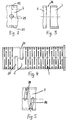
- the end of the calibration sleeve 2 has holes 25 distributed over its circumference, over which the measuring head (s) 20 are arranged are to measure the wall thickness of the tube 16 drawn through the calibration sleeve 3.
- the measurement is carried out through the assigned bores 25 without being obstructed by the calibration sleeve 3.
- the end region 4 is offset from the sleeve body of the calibration sleeve 3 with the formation of an intermediate space 26, and this makes it possible to run a measuring head around the pipe 16 rotating or reversing in the intermediate space 26 allow.
- a straight-line guidance of the tube is not interrupted since the tube is guided in the calibration sleeve 3 as well as in its end region 4 and thus in front of and behind the measuring point in the intermediate space 26 under the same conditions.
- the end region 4 is fastened in the sliding seal 8.
- FIG. 4 shows the arrangement of the end region 4 of the calibration sleeve 3 for the arrangement of two rotating and / or reversing measuring heads 20, each of which moves over an angle range of 180 degrees and moves around the tube 16.
- the end region 4 of the calibration sleeve 3 has two grooves 27 which extend over 180 degrees and are arranged offset to one another in the longitudinal direction of the end region 4, so that the two are assigned Measuring heads can rotate and / or reverse in or over the grooves 27.
- the end region 4 of the calibration sleeve 3 has a groove 28 which extends helically over 360 degrees, and for this exemplary embodiment, a guide is required to guide the measuring head, which guides the measuring head with a 360 degree rotation and a predetermined offset in the axial direction of the calibration sleeve, whereby this axial offset of the total pitch of the helical groove 28 in the axial direction of the calibration sleeve 3 must correspond.
- the invention also includes an embodiment which is not shown in the drawing, namely the arrangement of static or rotating and / or reversing measuring heads which carry out the wall thickness measurement through the calibration sleeve, the values measured in this way being around the constants applicable to the calibration sleeve to be corrected.
- FIGS. 6 and 7 show two alternative embodiments of the partial aspect of the invention relating to the mounting of the measuring heads on the wall thickness measuring device.
- the frames 24 arranged in the measuring part 5 of the chamber 1 have a guide 29 connected to the wall of the chamber 1 and a plate 31 which is displaceably arranged in the guide 29 via cylinder 30, the plate 31 comes to lie on the face behind the end of the end region 4 of the calibration sleeve 3. For this reason, the front view of the end of the end region 4 of the calibration sleeve 3 is included in the view shown.
- plate 31 has two measuring heads 20 which are arranged with an axial offset in relation to the plate 31 in the longitudinal direction of the calibration sleeve, so that, starting from plate 31 lying on the end face at the end of the end area 4 of the calibration sleeve 3, the measuring heads 20 lie above the end area 4 the calibration sleeve 3 come to rest.
- FIG. 7 shows a corresponding arrangement for a rotationally reversing measuring head 20 which for this purpose is guided in a guide ring 32 over the circumference of the end section 4 of the calibration sleeve and is connected to a corresponding device via a drag chain 33 for energy supply and measured value transmission.
- a drive 34 ensures the movement of the measuring head 20 in the guide ring 32.
- the arrangement is provided on a plate 31 which is held vertically displaceably in fixed guides 29 via cylinders 30.
Landscapes
- Physics & Mathematics (AREA)
- General Physics & Mathematics (AREA)
- Engineering & Computer Science (AREA)
- Mechanical Engineering (AREA)
- Thermal Sciences (AREA)
- Extrusion Moulding Of Plastics Or The Like (AREA)
- Length Measuring Devices Characterised By Use Of Acoustic Means (AREA)
Applications Claiming Priority (2)
| Application Number | Priority Date | Filing Date | Title |
|---|---|---|---|
| DE4134285 | 1991-10-17 | ||
| DE4134285 | 1991-10-17 |
Publications (2)
| Publication Number | Publication Date |
|---|---|
| EP0537647A2 true EP0537647A2 (fr) | 1993-04-21 |
| EP0537647A3 EP0537647A3 (en) | 1993-08-18 |
Family
ID=6442827
Family Applications (1)
| Application Number | Title | Priority Date | Filing Date |
|---|---|---|---|
| EP19920117343 Ceased EP0537647A3 (en) | 1991-10-17 | 1992-10-10 | Extrusion installation with a wall thickness measuring apparatus for an extruded pipe |
Country Status (2)
| Country | Link |
|---|---|
| US (1) | US5346379A (fr) |
| EP (1) | EP0537647A3 (fr) |
Cited By (1)
| Publication number | Priority date | Publication date | Assignee | Title |
|---|---|---|---|---|
| CN110906832A (zh) * | 2019-11-04 | 2020-03-24 | 上海天庹智能设备有限公司 | 一种负压定位测量装置及其测量方法 |
Families Citing this family (15)
| Publication number | Priority date | Publication date | Assignee | Title |
|---|---|---|---|---|
| US5464335A (en) * | 1994-08-30 | 1995-11-07 | The Conair Group, Inc. | Vacuum tank for vacuum sizing apparatus |
| US5630982A (en) * | 1995-12-12 | 1997-05-20 | Sonoco Products Company | Method and apparatus for extruding plastic tubing |
| US6116882A (en) * | 1996-08-14 | 2000-09-12 | Owens Corning Fiberglas Technology, Inc. | Sealable chamber extrusion apparatus with seal controls |
| US6036468A (en) | 1997-08-21 | 2000-03-14 | Owens Corning Fiberglas Technology, Inc. | Vacuum extrusion system |
| EP0882565A1 (fr) * | 1997-06-02 | 1998-12-09 | CONPRO GmbH | Extrudeuse comportant une chambre de mesure avec un dispositif de mesure tournant autour du tube extrudé |
| AT408862B (de) * | 1997-12-22 | 2002-03-25 | Technoplast Kunststofftechnik | Vorrichtung zum abkühlen und kalibrieren von extrudierten kunststoffprofilen |
| US6109006A (en) * | 1998-07-14 | 2000-08-29 | Advanced Plastics Technologies, Ltd. | Process for making extruded pet containers |
| US6620354B1 (en) | 1999-11-29 | 2003-09-16 | The Conair Group, Inc. | Apparatus and method for producing and cutting extruded material using temperature feedback |
| US6488873B1 (en) | 1999-11-29 | 2002-12-03 | The Conair Group, Inc. | Apparatus and method for producing and cutting extruded material using temperature feedback |
| US8557884B2 (en) * | 2002-05-31 | 2013-10-15 | Owens Corning Intellectual Capital, Llc | To enhance the thermal insulation of polymeric foam by reducing cell anisotropic ratio and the method for production thereof |
| AT413272B (de) * | 2002-11-08 | 2006-01-15 | Technoplast Kunststofftechnik | Vorrichtung zum kühlen und kalibrieren von kunststoffprofilen |
| FR2850752B1 (fr) * | 2003-01-31 | 2005-12-30 | Actaris Sas | Joint d'etancheite de compteur de fluide et compteur equipe d'un tel joint |
| DE20305616U1 (de) * | 2003-04-04 | 2003-07-17 | Cepukaite-Urboneit, Rasa, 31711 Luhden | Einstellbare Kalibrierhülse |
| AT516900A1 (de) * | 2015-03-09 | 2016-09-15 | Dr Collin Gmbh | Vorrichtung und Verfahren zum Testen von Werkstoffen |
| CN115214107B (zh) * | 2022-07-22 | 2023-09-05 | 山东归仁新型材料科技有限公司 | 一种塑料管生产用定径装置 |
Family Cites Families (17)
| Publication number | Priority date | Publication date | Assignee | Title |
|---|---|---|---|---|
| US3546745A (en) * | 1968-02-29 | 1970-12-15 | Phillips Petroleum Co | Extrudate sizing sleeve |
| DE1809285A1 (de) * | 1968-11-16 | 1970-06-11 | Roehm & Haas Gmbh | Kalibrierbuechse mit Fluessigkeitskuehlung |
| DE1966994A1 (de) * | 1969-03-05 | 1976-03-18 | Bellaplast Maschinenbau Gmbh | Fluessigkeitsbad-kalibrator |
| US3916676A (en) * | 1972-07-05 | 1975-11-04 | Western Electric Co | Method of and apparatus for measuring automatically successive sections of an elongated material |
| US3856595A (en) * | 1973-04-16 | 1974-12-24 | Royle & Sons J | Measurement of dimension of elongated material during its continuous vulcanization |
| DE2505221A1 (de) * | 1975-02-06 | 1976-08-19 | Siemens Ag | Vorrichtung zur messung der wanddicke von extrudierten kunststoffschichten |
| DE2706085C2 (de) * | 1977-02-12 | 1984-02-02 | Reifenhäuser KG, 5210 Troisdorf | Vorrichtung zum Extrudieren von Rohren aus thermoplastischem Kunststoff |
| JPS55216A (en) * | 1978-05-22 | 1980-01-05 | Toshiba Corp | Bankbook printer |
| US4520672A (en) * | 1982-08-19 | 1985-06-04 | Saint Amour John D | Thickness measuring |
| NL8502034A (nl) * | 1985-07-15 | 1987-02-02 | Leer Koninklijke Emballage | Inrichting voor het vervaardigen van een buisvormig voorwerp. |
| US4740146A (en) * | 1986-07-25 | 1988-04-26 | Peter Angelbeck | Apparatus for measuring and controlling the wall thickness of plastic pipes |
| DE8816435U1 (de) * | 1988-02-12 | 1989-07-20 | Inoex GmbH Innovationen und Ausrüstungen für die Extrusionstechnik, 4970 Bad Oeynhausen | Wanddickenmeßvorrichtung für Rohre, Kabelummantelungen und dgl., insbesondere aus extrudiertem Kunststoff |
| DE3906363C1 (fr) * | 1989-03-01 | 1990-11-08 | Inoex Gmbh Innovationen Und Ausruestungen Fuer Die Extrusionstechnik, 4970 Bad Oeynhausen, De | |
| SE500696C2 (sv) * | 1989-03-10 | 1994-08-08 | Uponor Nv | Förfarande vid extrudering av plaströr |
| DE4002884C2 (de) * | 1989-09-28 | 1998-08-13 | Cincinnati Milacron Austria | Einrichtung zum Extrudieren von Rohren mit einer Strangpresse |
| EP0425944B1 (fr) * | 1989-10-31 | 1994-01-05 | INOEX GmbH | Installation d'extrusion pour des tubes en matière plastique |
| DE3936496A1 (de) * | 1989-11-02 | 1991-05-08 | Krauss Maffei Ag | Zentriervorrichtung fuer einen rohrextrusionskopf |
-
1992
- 1992-10-10 EP EP19920117343 patent/EP0537647A3/de not_active Ceased
- 1992-10-16 US US07/962,385 patent/US5346379A/en not_active Expired - Fee Related
Cited By (2)
| Publication number | Priority date | Publication date | Assignee | Title |
|---|---|---|---|---|
| CN110906832A (zh) * | 2019-11-04 | 2020-03-24 | 上海天庹智能设备有限公司 | 一种负压定位测量装置及其测量方法 |
| CN110906832B (zh) * | 2019-11-04 | 2021-09-03 | 上海天庹智能设备有限公司 | 一种负压定位测量装置及其测量方法 |
Also Published As
| Publication number | Publication date |
|---|---|
| EP0537647A3 (en) | 1993-08-18 |
| US5346379A (en) | 1994-09-13 |
Similar Documents
| Publication | Publication Date | Title |
|---|---|---|
| EP0537647A2 (fr) | Installation d'extrusion avec dispositif de mesure de l'épaisseur pour tuyau extrudé | |
| DE2256653A1 (de) | Pruefgeraet fuer reaktorbehaelter | |
| DE2754131A1 (de) | Vorrichtung fuer die entnahme einer fluessigkeit aus einer vielzahl von leitungen | |
| EP0385285B1 (fr) | Dispositif pour extruder des tuyaux en matière plastique | |
| DE4032305C2 (de) | Vorrichtung zum Untersuchen des vorderen Endabschnittes einer Tunnelvortriebsmaschine | |
| DE2706085C2 (de) | Vorrichtung zum Extrudieren von Rohren aus thermoplastischem Kunststoff | |
| EP0398002B1 (fr) | Dispositif pour l'examen automatique par ultra-son des extrémités de tuyaux | |
| DE10136686B4 (de) | Laserbearbeitungskopf zur Bearbeitung eines Werkstücks mittels eines Laserstrahls | |
| DE2749536C3 (de) | Anordnung zum Messen der Vorspannung eines insbesondere zum Verschluß eines Reaktordruckbehälters dienenden Schraubenbolzens | |
| DE4019865C2 (fr) | ||
| CH635434A5 (de) | Spinresonanz-spektrometer mit einem an leitungen angeschlossenen probengefaess. | |
| DE102013008347B4 (de) | Ziehsteinanordnung, Werkstückführung und Ziehanlage mit einer Ziehmaschine | |
| DE1533829B1 (de) | Sonde zur gas und moellerprobenentnahme und oder temperatur sowie gasdruckmessung bei schachtoefen insbesondere hoch oefen | |
| WO2001088452A1 (fr) | Rouleau de transport refroidi par eau destine a un four a rouleaux | |
| DE2653791A1 (de) | Vorrichtung fuer kreisfoermige behaelter | |
| DE69222348T2 (de) | Elektromagnetische Rühreinrichtung für das Stranggiessen | |
| DE2948547A1 (de) | Vorrichtung zur zerstoerungsfreien pruefung langgestreckter pruefstuecke mit ultraschallimpulsen | |
| DE20023052U1 (de) | Kalibrierhülse mit variabler Durchmessereinstellung | |
| DE4410580B4 (de) | Ultraschall-Prüfungsmaschine für längliche Prüfstücke mit einem Rotor und einem Stator | |
| EP0056215A1 (fr) | Procédé et appareil pour l'examen de cordes coulées dans une installation de coulée continue | |
| DE19834731C1 (de) | Meßvorrichtung und Verfahren zum Bestimmen des Durchmessers eines HDI-Körpers | |
| EP0882565A1 (fr) | Extrudeuse comportant une chambre de mesure avec un dispositif de mesure tournant autour du tube extrudé | |
| DE3207193C2 (de) | Extruderzylinderabschnitt in einem Mehrschneckenextruder für Kunststoff | |
| DE2845961C3 (de) | Spinresonanz-Spektrometer | |
| DE3817781C1 (en) | Hose maintenance line with two washing positions |
Legal Events
| Date | Code | Title | Description |
|---|---|---|---|
| PUAI | Public reference made under article 153(3) epc to a published international application that has entered the european phase |
Free format text: ORIGINAL CODE: 0009012 |
|
| AK | Designated contracting states |
Kind code of ref document: A2 Designated state(s): AT BE CH DE DK ES FR GB IT LI NL SE |
|
| PUAL | Search report despatched |
Free format text: ORIGINAL CODE: 0009013 |
|
| AK | Designated contracting states |
Kind code of ref document: A3 Designated state(s): AT BE CH DE DK ES FR GB IT LI NL SE |
|
| 17P | Request for examination filed |
Effective date: 19940216 |
|
| 17Q | First examination report despatched |
Effective date: 19950712 |
|
| 18R | Application refused |
Effective date: 19951229 |