EP0537766A2 - Dispositif pour la mesure du débit massique selon le principe Coriolis - Google Patents
Dispositif pour la mesure du débit massique selon le principe Coriolis Download PDFInfo
- Publication number
- EP0537766A2 EP0537766A2 EP92117724A EP92117724A EP0537766A2 EP 0537766 A2 EP0537766 A2 EP 0537766A2 EP 92117724 A EP92117724 A EP 92117724A EP 92117724 A EP92117724 A EP 92117724A EP 0537766 A2 EP0537766 A2 EP 0537766A2
- Authority
- EP
- European Patent Office
- Prior art keywords
- mass flow
- measuring
- conveyed
- measuring device
- torque
- Prior art date
- Legal status (The legal status is an assumption and is not a legal conclusion. Google has not performed a legal analysis and makes no representation as to the accuracy of the status listed.)
- Withdrawn
Links
Images




Classifications
-
- G—PHYSICS
- G01—MEASURING; TESTING
- G01F—MEASURING VOLUME, VOLUME FLOW, MASS FLOW OR LIQUID LEVEL; METERING BY VOLUME
- G01F1/00—Measuring the volume flow or mass flow of fluid or fluent solid material wherein the fluid passes through a meter in a continuous flow
- G01F1/76—Devices for measuring mass flow of a fluid or a fluent solid material
- G01F1/78—Direct mass flowmeters
- G01F1/80—Direct mass flowmeters operating by measuring pressure, force, momentum, or frequency of a fluid flow to which a rotational movement has been imparted
- G01F1/84—Coriolis or gyroscopic mass flowmeters
- G01F1/845—Coriolis or gyroscopic mass flowmeters arrangements of measuring means, e.g., of measuring conduits
- G01F1/8454—Coriolis or gyroscopic mass flowmeters arrangements of measuring means, e.g., of measuring conduits rotating or rotatingly suspended measuring conduits
-
- G—PHYSICS
- G01—MEASURING; TESTING
- G01F—MEASURING VOLUME, VOLUME FLOW, MASS FLOW OR LIQUID LEVEL; METERING BY VOLUME
- G01F1/00—Measuring the volume flow or mass flow of fluid or fluent solid material wherein the fluid passes through a meter in a continuous flow
- G01F1/76—Devices for measuring mass flow of a fluid or a fluent solid material
- G01F1/78—Direct mass flowmeters
- G01F1/80—Direct mass flowmeters operating by measuring pressure, force, momentum, or frequency of a fluid flow to which a rotational movement has been imparted
Definitions
- the invention relates to a method and a device for determining the mass flow of a conveyed good according to the Coriolis principle, in particular bulk goods, according to the preamble features of patent claim 1.
- Such a method and device for determining the flow of a mass flow is known from DE 25 44 976 A1.
- the throughput of bulk material in the iron industry such as lime dust or fine ore, is to be determined.
- the change in drive torque that occurs is used here as a measured variable for determining the mass flow.
- the mass flow is directed onto a rotating measuring wheel with radial guide vanes, the bulk material being thrown away essentially perpendicular to the axis of rotation of the measuring wheel.
- the torque of the measuring wheel rotating at an approximately constant speed changes in accordance with the Coriolis force, the change in the drive torque being proportional to the mass of the material flow flowing through.
- the power consumption of the drive motor that drives the measuring wheel is used in this publication.
- the object of the invention is to provide a method and a device for mass flow determination which achieves greater measurement accuracy, is simple in construction and can be used as universally as possible for different types of conveyed goods.
- the upstream connection of a conveying fluid measuring device proposed here also detects the mass flow of the conveying gas or the conveying liquid, so that the quantity of fluid conveyed is also taken into account when determining the mass. Since the conveying gases or liquids are no longer neglected, in particular in the case of high conveying capacities, such as are sought in the interest of a high throughput, the measuring accuracy is significantly higher.
- the proposed device for mass flow determination can be easily installed in existing pneumatic conveying systems, with the additional conveying fluid measuring device proposed here at the same time increasing the conveying capacity since the measuring wheel can also be designed as a conveying fan.
- This device can be installed at almost any angle between a horizontal position or a vertical arrangement, so that it can be installed in particular in any bulk material conveying system. It is also of particular advantage that the delivery rate can be varied or regulated by the action of the measuring wheel or feed wheel as a blower via its change in speed.
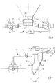
- Fig. 1 the proposed device for mass flow determination is shown schematically.
- This essentially consists of a mass flow measuring device 1 known per se, a loading device 2 and a now proposed additional conveying fluid measuring device 3.
- the mass flow measuring device 1 essentially consists of a measuring wheel 4, the guide vanes 5 for the radial deflection of the mass flow M2 the loading device 2 carries. A certain angular velocity is impressed on the inflowing mass flow by the guide vanes 5. The force required for this is directly proportional to the mass flow.
- the bulk material flow M2 is fed from the loading device 2 to the measuring wheel 4 in a central feed area 7.
- the bulk material is detected by the guide vanes 5 at the angular velocity of the rotating measuring wheel 4 and accelerated to the outside by centrifugal forces.
- the bulk particles leave the measuring wheel 4 on all sides at the discharge edge of the guide vanes 5.
- the Coriolis acceleration which occurs when the bulk material particles move along the guide vanes 5 results in a reaction or braking moment on the measuring wheel 4, which is used here as a measuring effect .
- the total mass flow M1 which results from the conveyed material or here Bulk mass flow M2 and the air mass flow M3 composed, recorded.
- the measuring wheel 4 is connected via a shaft 6 to a drive motor 8, which is oscillating and, when the drive torque changes, is supported in proportion to the throughput quantity against a load cell 9 fastened at a distance from the shaft 6.
- a drive motor 8 which is oscillating and, when the drive torque changes, is supported in proportion to the throughput quantity against a load cell 9 fastened at a distance from the shaft 6.
- the bulk material flow M2 to be measured is passed through the loading device 2, here simply a feed hopper 10 through a type of injector 11 into the central feed area 7 of the measuring wheel 4 and leaves it after radial deflection through the guide vanes 5 , wherein a housing 12 surrounding the measuring wheel 4 summarizes the mass flow and forwards it to a subsequent delivery line or a bulk material outlet.
- the exemplary embodiments are described in a simplified manner using a bulk material flow as an example of a conveyed material.
- a conveying fluid air is used here as well as in general when using the proposed device.
- the proposed method and the device is applicable to all flowable components of the same or different composition and the same or different aggregate states.
- Flowable, fine-grained solids such as sand, grain, flour, powder or granules of any kind in particular serve as flowable conveyed material.
- gases and, in turn, air come into consideration as the conveying fluid, but liquids or gas / liquid mixtures can also be used for this purpose.
- the proposed device and the method are therefore suitable for Mass flow determination preferably of heterogeneous multi-substance mixtures, but also of mixtures with a homogeneous composition.
- the total mass can also be determined in a specific time unit by means of a corresponding, known evaluation.
- an air flow measuring device 3 for measuring the air mass flow M3, which essentially consists of an air inlet 13, an impeller 14 for accelerating the conveying gas and a housing 15, if necessary. with a stator not shown for rectifying the air flow M3 shown in dashed lines in the lower half.
- an outlet opening 16 is provided for the air flow M3, which thereby entrains the bulk material located in the feed hopper 10 as a bulk material flow M2 and guides it via the injector 11 into the central feed area 7 of the mass flow measuring device 1.
- the impeller 14 for accelerating and measuring the conveying air flow M3 is connected via a shaft 17, which partially encompasses the first shaft 6 and is mounted independently, to a second drive motor 18, which is also mounted in an oscillating manner and is supported by a load cell 19.
- a measured value M1 is obtained at the other force measuring cell 9, which is proportional to the total mass flow M1 flowing through the measuring device 1 as the sum of the bulk material mass flow M2 and the conveying gas mass flow M3.
- only the mass of the conveying air or the conveying fluid is measured at the force measuring cell 19 as measured value M3.
- the two measuring devices 1 and 3 rotating in opposite directions, so that mutually directed torques M1 and M3 are available as a measure of the mass flows M1 and M3, as indicated by the arrows.
- Both pendulum-suspended drive motors 8 and 18 act on a single force measuring cell, so that the differential torque M2 results directly at the force measuring cell 9 and can be read off from the evaluation device 20 as a mass flow or used for further manual control or automatic regulation.
- the speed of the measuring device 1 or the measuring wheel 4 can be increased so that the amount of suction M2 from the injector 11 increases.
- the speed of the feed wheel 14 can also be increased, so that a larger bulk material flow M2 is entrained into the injector 11 via the higher air volume, more precisely the higher air mass flow M3.
- the conveying fluid measuring device 3 can also be formed by a compressor, the drive torque of which is detected and is proportional to the flow rate of the conveyed gas M3, as will be explained in more detail in FIG. 10.
- the torque tapping on the conveying gas flow measuring device 3 and the mass flow measuring device 1 for the corresponding measured values M3 and M1 can differ from the torque measuring device 9, 19 shown here with a rotatably mounted motor, which at the same time forms the lever for a load cell be designed For example, be replaced by a correspondingly accurate measurement of the current consumption of the drive motors 8 and 18.
- cellular wheel sluices or screw conveyors or similar metering devices can also be provided as the charging device 2, as is shown in the exemplary embodiments below.
- a modified embodiment is shown in FIG. 2, with a further measuring device 23 being connected in the manner of a series connection with the interposition of a further loading device 22 compared to the embodiment in FIG. 1.
- the measuring device 23 with its main components, namely a measuring wheel 24, a drive motor 28 and a torque measuring device 29 has essentially the same structure, but the drive motors, in contrast to the embodiment in Fig. 1, in the immediate vicinity of the measuring or Vane wheels 4, 14 and 24 are arranged.
- a further conveyed material component M5 can thus be added to the loading device 22, as is more frequently required in the case of granule mixtures.
- a gas component can also be introduced, for example, at the air inlet 13, a liquid component at the charging device 2 and a solid component at the charging device 22.
- the respective Coriolis force is recorded as a reaction torque on the load cells 9, 19 and 29 and passed on to the evaluation unit as measurement signals M1, M3 and M4.
- the differential torque M2 is formed from the measured values M3 and M1, which is directly proportional to the mass flow M2 of the component added to the charging device 2.
- the mass flow M5 of the component that is added to the loading device 22 the differential moment M5 being formed here from the total mass flow measured on the measuring device 23 in accordance with the measured value M4 and the measured value M1 determined by the measuring device 1.
- the arrangement of three measuring devices shown here lets expand to a large number so that any number of components for dosing can be measured.
- Fig. 3 one of the three series-connected measuring devices from Fig. 2 is shown enlarged, here the middle measuring device 1.
- the two upstream and downstream measuring devices 3 and 23 can have exactly the same structure, so that a modular construction is possible .
- the drive motor 8 is arranged in the immediate vicinity of the measuring wheel 4.
- the remaining reference numerals for functionally identical parts correspond to those of Fig. 1.
- the drive motor 8 is rotatably mounted in an intermediate housing 30 so that its housing is supported against the force measuring cell 9 when the Coriolis force occurs in measuring operation, and thus for each proportional braking torque flowing through the mass flow.
- the intermediate housing 30 is non-rotatably connected to the housing 12 via ribs 31.
- a pipe 32 leads out of the intermediate housing 30, which serves to guide the exhaust air of the drive motor 8 and can accommodate the power supply cables and the data lines from the load cell 9.
- the measuring wheel 4 with radial guide vanes 5 reaching up to the feed region 7 is fastened to the motor shaft of the drive motor 8 via a tie rod 33.
- a flow straightener 34 is provided in front of the feed area to avoid a swirl.
- the measuring wheel 4 is swept in the direction of flow, so that there is an aerodynamically favorable forwarding of the bulk material and air flow with pneumatic conveying.
- the arrow angle of the measuring wheel 4 is chosen such that, depending on the density of the material being conveyed, it is conveyed to the outside as far as possible without touching the outer and inner surfaces.
- the ends of the guide vanes 5 facing the feed area 7 are bent or folded in the circumferential direction, so that the conveyed material particles are given a radial acceleration as soon as they enter the measuring wheel 4 and they assume the angular velocity of the measuring wheel 4 as smoothly as possible.
- the ribs 31 can also be designed as a rectifier, so that the flow through the measuring device 1 is as low as possible.
- the tube 32 is also oval in the flow direction or provided with a drop-shaped cross section.
- the arrow-shaped design of the measuring wheel 4 also results in a compact design, so that the measuring device is easy to install, particularly in pneumatic conveying systems. This is shown by way of example in the following figures.
- FIG. 4 shows a third embodiment which, like the embodiment in FIG. 1, has two measuring devices 1 and 3, but which are provided here in a vertical arrangement.
- a blow-through lock 40 on the underside of a feed hopper 10, z. B. provided from a silo.
- the blow-through lock 40 has a metering rotor 42 which rotates in a closed housing 41 around a drive shaft 44.
- the metering rotor 42 is driven by a gear 45 and a drive motor 46, conveyor pockets 43 arranged on the outer circumference of the metering rotor 42 running past the feed opening under the feed hopper 10 and blown out on the opposite side after a rotation of approximately 180 ° by conveying air supplied at the air inlet 13 will.
- the mass M3 of the conveying air is detected in the manner described above by measuring the reaction torque M3 acting on the conveying wheel 14, which is determined on the load cell 19.
- the total mass flow M1 of the conveyed material M2 drawn off from the feed hopper 10 is recorded on the upper measuring device 1 together with the conveying gas M3 entering at the air inlet 13.
- the differential torque M2 which is proportional to the mass of the conveyed material, is formed.
- the feed wheel 14 not only serves to measure the Coriolis force, but also serves to generate the air flow for the conveyance in the vertical direction.
- the conveying or blower effect of the conveying wheel 14 is sufficient for lower delivery heights and light goods to be conveyed.
- an additional blower can also be provided at the air inlet 13.
- the fluidized-bed lock 50 essentially consists of a hermetically sealed pressure vessel 51, into which compressed air is introduced from the underside 52 to fluidize and loosen the conveyed material located in the pressure vessel.
- the mass M3 of the introduced compressed air is detected by the measuring device 3.
- a compressor or a blower 56 can be connected upstream to support the conveying action of the conveying wheel 14.
- the conveyed material arrives from the pressure vessel 51 via a conveying line 53 to the measuring device 1, which in turn detects the total mass flow M1 from the conveyed material mass flow M2 and the conveying fluid mass flow M3, here the compressed air.
- the measuring wheel 4 of the measuring device 1 can advantageously serve in addition to the compressed air injection on the underside 52 for suction of the conveyed material.
- a bulk material bunker 54 is provided, the emptying amount of which is controlled via a cellular wheel sluice 55 so that the bulk height of the conveyed material in the pressure vessel 51 remains approximately constant.
- the rotary valve 55 is designed so that the best possible seal against leakage air is achieved, so that the amount of air flowing into the pressure vessel 51 M3 and the total mass flow M1 leaving the pressure vessel 51 from conveyed material and conveying fluid without leakage air is to be determined exactly.
- the mass flow of material to be conveyed M2 in the evaluation device 20 is then determined from these measured values by forming the difference (M1-M3).
- FIG. 6 shows a fifth exemplary embodiment which has a structure similar to that in FIG. 4, but is arranged essentially horizontally here.
- a metering roller 60 rotating around a horizontal axis is provided as the charging device 2 between the measuring arrangement 1 for the total mass flow M1 and the measuring arrangement 3 for the supply air mass flow M3.
- the metering roller 60 has recesses 61 on its outer circumference, which run downward after the conveyed material has been taken along and are transported there from the conveying air entering through the measuring device 3 to the right to the measuring device 1.
- the torque which is proportional to the total mass flow M1 from the conveyed material and conveyed air, is again measured on a force measuring cell 9 and fed to the evaluation device 20.
- the reaction moment M3 which is proportional to the mass flow of the conveyed air and which was detected by the load cell 19, is subtracted, so that the mass flow M2 of the conveyed material is obtained without the error moment of the conveyed fluid.
- FIG. 7 quasi shows the reversal of the previous exemplary embodiments in use in a suction conveyor system 70.
- a suction nozzle 71 With a suction nozzle 71, the conveyed material shown in dotted lines is sucked out of a ship's hull, considerable quantities of air being sucked in at the suction nozzle 71.
- the mixture of conveyed material and conveyed air first passes through the measuring device 1, which thus determines the total mass flow M1 of the conveyed material with the conveyed fluid.
- the material to be conveyed is largely separated in a cyclone separator 72 from the suctioned conveyed material / conveying fluid mixture and fed to a silo 74 via a rotary valve 73.
- the rotary valve 73 serves to seal the entire suction system. From the cyclone separator 72, the mixture containing only small amounts of material to be conveyed enters one Filter 75, again a high percentage of the conveyed material being separated and fed to the silo via a rotary valve 76. The conveying air passes from the filter 75 via the measuring device 3 to the suction fan 77, which essentially operates the entire suction conveyor 70. In the measuring device 3, the mass flow M3 of the conveying air and fine dust remaining therein is thus determined.
- FIG. 8 shows a further exemplary embodiment of measuring devices 1 and 3 connected in series, shown here only schematically. It is essential here that both measuring or feed wheels 4 and 14 are driven by a single motor 8. In this way, in addition to saving the second drive motor 18, an exact synchronous operation and thus exactly the same speed of rotation of the two measuring rotors 4 and 14 can be achieved. In this way, the speed of both measuring wheels 4 and 14 can be regulated to control the flow rate.
- the exemplary embodiment is furthermore that the torque measurement takes place here outside the housing 12 and thus outside the flow path of the conveyed material and the conveying fluid.
- the measuring wheels 4 and 14 are mounted on cantilever arms 80 and 81 which are connected via an intermediate tube 82.
- the latter and the arms 80 and 81 receive a gear, preferably two belt drives 83 with an intermediate shaft 84 in a dust-tight manner.
- the cantilever arms 80 and 81 protrude into closed recesses 88 in the housing 12, which surround the former with little play.
- the cantilever arms 80 and 81 can rotate slightly about the shafts 6 and 17 of the measuring wheels 4 and 14 and thus pass on torque changes.
- a reversal of the direction of rotation is achieved via the intermediate shaft 84, so that the two measuring wheels 4 and 14 rotate in opposite directions.
- a parallelogram linkage 85 is fastened to the intermediate tube 82 and acts on the force measuring cell 9 provided for torque measurement via a vertical link 86, as can be seen from the sectional view along section line BB.
- the parallelogram linkage 85 is designed so that the intermediate tube 82 is statically determined and tied.
- the handlebar 86 is for support at a support point 87 on z. B. particularly low-friction cross spring joints fixed. Due to the opposite direction of rotation of the measuring wheels 4 and 14, the displacement of the linkage 85 and thus the action on the load cell 9 (see associated section BB) is proportional to the differential torque between the measuring devices 1 and 3. This differential torque is in turn proportional to the mass flow of the conveyed material, so that with appropriate calibration of the load cell 9, taking into account the lever length 86, the mass flow of the material to be conveyed can be determined directly without the influence of the error in the conveying air. It is particularly advantageous that the linkage 85 is considerably less friction than a roller bearing and also also the pivot bearing 89 easily respond to changes in torque by mounting directly on the shafts 6 and 17.
- a breakthrough in the cantilever arm 81 and the bulge 88 is also indicated by dash-dotted lines, so that conveyed material can pass through here, provided the belt drive 83 runs on the outside of the cantilever arm 81 and is encapsulated.
- FIG. 9 shows an embodiment similar to that shown in FIG. 8, but here the measuring devices 1 and 3 with their measuring wheels 4 and 14 are arranged parallel to one another instead of connected in series.
- a separate drive motor 8 or 18 is provided for each measuring device. Due to the parallel arrangement next to one another, the torque can be tapped via a double-sided parallelogram linkage 85, which in turn is mounted on a support point 87 and acts on the load cell 9 via a vertical link 86.
- This arrangement taps a measured value proportional to the differential torque (M1-M3) from the load cell 9.
- This arrangement is suitable for. B. also for the suction conveyor system 70 in Fig. 7, by the measuring devices 1 and 3 there can be arranged side by side by appropriate conveying line.
- Fig. 10 a simplified embodiment is shown, which differs from the embodiment in Fig. 4 essentially in that the measuring device 3 for the conveying fluid is not formed by a Coriolis measuring wheel with a torque tap, but on a rotary blower 90 the mass flow of Conveying fluids are provided as a measuring device 3 by a hot wire air quantity or air mass meter, shown schematically here.
- the drive torque for the rotary lobe blower can also be tapped as a measured variable for the air mass flow or a corresponding air damper or similar air flow meter known from the motor vehicle for the intake air measurement can also be used.
- a dynamic pressure measurement can also be carried out to detect the air flow mass flow M3.
- a screw compressor or a radial blower can of course also be provided, depending on the required delivery pressure.
- the measured values of the measuring device 3 are fed to the evaluation device 20 and converted there into a measured variable proportional to the mass flow. Together with the measured value of the load cell 9 as a direct measure of the mass flow of the conveyed material from the feed hopper 10 together with the conveying air, the difference value is again formed from M1 - M3, so that the net mass flow M2 of the conveyed good alone, without the influence of the error of the additional conveying air mass is determined.
- FIG. 11 A further embodiment is shown in FIG. 11, the mass flow detection of the air quantity M3 supplied by a compressor 90 taking place in a turbine 91, the turbine wheel of which thus forms the measuring device 3 for the conveying fluid.
- the turbine 91 is also suitable for liquids and has the particular advantage that the turbine 91 also serves as an air or liquid motor and thus for driving the measuring wheel 4 of the measuring device 1. That caused on the turbine 91 by the fluid flow M3 Torque is transmitted to a reversing gear 94 via its shaft, which is mounted in position 93 in a rectifier 92. There, the torque of the turbine 91 is conducted via an intermediate shaft 95 and a reversing wheel 96 to the shaft 6 of the measuring wheel 4 and possibly reduced.
- the shaft 6 is supported by a bearing 98 in a further rectifier 97.
- the gear housing 94 is rotatably mounted on the two stub shafts and is supported on the load cell 9 via a lever which projects laterally. Since the turbine 91 and measuring wheel 4 rotate in opposite directions, the torque applied to the load cell 9 corresponds to the difference between the right and left turning moments here the moment M1 for the total mass flow minus the moment M3 from the air delivery.
- the differential torque M2 for the quantity of material to be conveyed M2 can thus be obtained directly at the load cell 9 and forwarded to the evaluation or display device 20, to which a speed measuring device 99 is also connected. About product formation ( M2 xn ) can thus determine the delivery rate and z. B.
Landscapes
- Physics & Mathematics (AREA)
- Fluid Mechanics (AREA)
- General Physics & Mathematics (AREA)
- Measuring Volume Flow (AREA)
Applications Claiming Priority (2)
| Application Number | Priority Date | Filing Date | Title |
|---|---|---|---|
| DE4134319A DE4134319C2 (de) | 1991-10-17 | 1991-10-17 | Verfahren und Vorrichtung zur Massenstrombestimmung nach dem Coriolis-Prinzip |
| DE4134319 | 1991-10-17 |
Publications (2)
| Publication Number | Publication Date |
|---|---|
| EP0537766A2 true EP0537766A2 (fr) | 1993-04-21 |
| EP0537766A3 EP0537766A3 (en) | 1993-09-29 |
Family
ID=6442854
Family Applications (1)
| Application Number | Title | Priority Date | Filing Date |
|---|---|---|---|
| EP19920117724 Withdrawn EP0537766A3 (en) | 1991-10-17 | 1992-10-16 | Device for measuring the mass flow rate following the coriolis principle |
Country Status (4)
| Country | Link |
|---|---|
| US (1) | US5301555A (fr) |
| EP (1) | EP0537766A3 (fr) |
| CA (1) | CA2080795C (fr) |
| DE (1) | DE4134319C2 (fr) |
Cited By (3)
| Publication number | Priority date | Publication date | Assignee | Title |
|---|---|---|---|---|
| DE19523026A1 (de) * | 1995-06-24 | 1997-01-02 | Same Spa | Verfahren und Vorrichtung zur Messung eines Massestromes |
| DE19542290A1 (de) * | 1995-11-14 | 1997-05-15 | Schenck Ag Carl | Meßrotor für Massendurchflußmeßgeräte |
| EP0864850A1 (fr) * | 1997-03-11 | 1998-09-16 | S.E.G. Mekanik Ab | Tube d'admission pour un débitmètre massique |
Families Citing this family (9)
| Publication number | Priority date | Publication date | Assignee | Title |
|---|---|---|---|---|
| DE4442462B4 (de) * | 1994-11-29 | 2005-04-14 | Pfister Gmbh | Verfahren und Vorrichtung zur Massenstrombestimmung nach dem Coriolis-Prinzip |
| DE4443053A1 (de) | 1994-12-05 | 1996-06-13 | Pfister Gmbh | Verfahren und Vorrichtung zur kontinuierlichen, gravimetrischen Dosierung und Massenstrombestimmung von fließfähigen Gütern |
| US5665910A (en) * | 1995-10-23 | 1997-09-09 | Knutson; Scott William | Liquid chemical applicator measuring device |
| DE19605910B4 (de) * | 1996-02-17 | 2005-04-21 | Schenck Process Gmbh | Vorrichtung zum Messen eines Massestroms nach dem Coriolis-Meßprinzip |
| DE19800486C2 (de) * | 1998-01-09 | 2002-07-11 | Amazonen Werke Dreyer H | Pneumatische Drillmaschine oder pneumatischer Düngerstreuer |
| DE10242156B4 (de) * | 2002-09-11 | 2013-01-03 | Schenck Process Gmbh | Massendurchflußmeßvorrichtung |
| US20180340808A1 (en) * | 2017-05-29 | 2018-11-29 | Mingsheng Liu | Torque Based Flowmeter Device and Method |
| CN108534159B (zh) * | 2018-04-28 | 2023-08-08 | 河南禾力能源有限公司 | 一种工业锅炉排渣用空压机的自动调压装置 |
| CN115318167A (zh) * | 2022-09-06 | 2022-11-11 | 李广侠 | 一种塑料助剂加工工艺 |
Family Cites Families (15)
| Publication number | Priority date | Publication date | Assignee | Title |
|---|---|---|---|---|
| US3171280A (en) * | 1959-05-21 | 1965-03-02 | Gen Electric | Mass flowmeter |
| US3613450A (en) * | 1968-04-02 | 1971-10-19 | Philip K Bodge | Fluid mass flowmeter |
| FR2042520B1 (fr) * | 1969-05-09 | 1974-05-24 | Elliott Bros | |
| DE2544976A1 (de) * | 1975-10-08 | 1977-04-14 | Maximilianshuette Eisenwerk | Verfahren und vorrichtung zum bestimmen des durchflusses eines massestroms |
| US4083243A (en) * | 1977-04-22 | 1978-04-11 | The United States Of America As Represented By The United States Department Of Energy | Method of measuring the mass flow rate of a substance entering a cocurrent fluid stream |
| US4198860A (en) * | 1978-02-27 | 1980-04-22 | Phillips Petroleum Company | Method and apparatus for measuring particulate matter flow rate |
| SU761839A1 (ru) * | 1978-07-31 | 1980-09-07 | Vadim V Almazov | Способ измерения массового расхода жидкостей и газов и устройство для его осуществления 1 2 |
| DE2925510A1 (de) * | 1979-06-25 | 1981-01-15 | Schenck Ag Carl | Verfahren und vorrichtung zur messung der foerderstaerke in einer pneumatischen foerderanlage |
| US4341107A (en) * | 1980-10-14 | 1982-07-27 | Tylan Corporation | Calibratable system for measuring fluid flow |
| JPS57207826A (en) * | 1981-06-17 | 1982-12-20 | Hideo Nagasaka | Measuring device for flow rate of pulverulent body |
| DE3346145C2 (de) * | 1983-12-21 | 1986-02-13 | Claus 6304 Lollar Friedrich | Meßvorrichtung zur kontinuierlichen Ermittlung der Durchsatzmenge von Materialströmen |
| US4711132A (en) * | 1984-06-04 | 1987-12-08 | Exac Corporation | Apparatus for mass flow rate and density measurement |
| US4691578A (en) * | 1986-02-21 | 1987-09-08 | Fischer & Porter Company | Coriolis-type mass flowmeter |
| DE3633694C3 (de) * | 1986-10-03 | 1997-04-30 | Schenck Ag Carl | Verfahren und Vorrichtung zur kontinuierlichen Messung der Förderstärke eines Schüttgutstromes |
| DE3940576A1 (de) * | 1989-12-08 | 1991-06-13 | Cra Services | Vorrichtung zur messung eines massestromes |
-
1991
- 1991-10-17 DE DE4134319A patent/DE4134319C2/de not_active Expired - Lifetime
-
1992
- 1992-10-16 US US07/961,941 patent/US5301555A/en not_active Expired - Lifetime
- 1992-10-16 EP EP19920117724 patent/EP0537766A3/de not_active Withdrawn
- 1992-10-16 CA CA002080795A patent/CA2080795C/fr not_active Expired - Lifetime
Cited By (3)
| Publication number | Priority date | Publication date | Assignee | Title |
|---|---|---|---|---|
| DE19523026A1 (de) * | 1995-06-24 | 1997-01-02 | Same Spa | Verfahren und Vorrichtung zur Messung eines Massestromes |
| DE19542290A1 (de) * | 1995-11-14 | 1997-05-15 | Schenck Ag Carl | Meßrotor für Massendurchflußmeßgeräte |
| EP0864850A1 (fr) * | 1997-03-11 | 1998-09-16 | S.E.G. Mekanik Ab | Tube d'admission pour un débitmètre massique |
Also Published As
| Publication number | Publication date |
|---|---|
| DE4134319C2 (de) | 2001-06-07 |
| EP0537766A3 (en) | 1993-09-29 |
| CA2080795A1 (fr) | 1993-04-18 |
| DE4134319A1 (de) | 1993-04-22 |
| CA2080795C (fr) | 2003-08-19 |
| US5301555A (en) | 1994-04-12 |
Similar Documents
| Publication | Publication Date | Title |
|---|---|---|
| DE3346145C2 (de) | Meßvorrichtung zur kontinuierlichen Ermittlung der Durchsatzmenge von Materialströmen | |
| DE4134319C2 (de) | Verfahren und Vorrichtung zur Massenstrombestimmung nach dem Coriolis-Prinzip | |
| DE102005003620A1 (de) | Verfahren und Vorrichtung zur pneumatischen Förderung von schwerfließendem Schüttgut | |
| DE2544976A1 (de) | Verfahren und vorrichtung zum bestimmen des durchflusses eines massestroms | |
| EP0468399B1 (fr) | Dispositif pour le dosage et/ou le mélange continu, pneumatique gravimetrique de marchandises en vrac | |
| WO1996018088A1 (fr) | Procede et dispositif permettant un dosage gravimetrique continu et une determination du debit massique de matieres coulantes | |
| EP0476249B1 (fr) | Dispositif et procédé pour transporter et mélanger du matériau en vrac | |
| EP1362224B1 (fr) | Dispositif de dosage | |
| CH662995A5 (de) | Einrichtung zum dosieren von schuettgut. | |
| CH687869A5 (de) | Mikrodosiergeraet. | |
| DE19749873A1 (de) | Verfahren und Vorrichtung zur kontinuierlichen Dosierung | |
| EP0588297B1 (fr) | Appareil de dosage | |
| SU1414436A1 (ru) | Смесительна установка | |
| DE20109074U1 (de) | Vorrichtung zur kontinuierlichen Messung und Regelung des Massenstromes | |
| EP0980509B1 (fr) | Doseur | |
| DE10134205B4 (de) | Prallplatten-Durchflußmeßvorrichtung | |
| DE10103854A1 (de) | Messvorrichtung und Verfahren zur Ermittlung eines kontinuierlichen Massenstroms von fliessfähigen Gütern | |
| EP1032808B1 (fr) | Dispositif de dosage gravimetrique pour materiaux en vrac | |
| DE8316568U1 (de) | Dosiereinrichtung fuer staubfoermiges schuettgut | |
| DE19729285A1 (de) | Dosiereinrichtung für in Behältnisse abzufüllende Schüttgüter | |
| DE3320477A1 (de) | Dosiereinrichtung fuer staubfoermiges schuettgut | |
| DD292970A5 (de) | Dosiereinrichtung | |
| AT230169B (de) | Verfahren und Vorrichtung zum Regeln der Beschickung einer Rohrmühle | |
| DD239467A1 (de) | Durchsatzmess- und dosiereinrichtung fuer schuettgueter | |
| CH691747A5 (de) | Messrotor für Massendurchflussmessgeräte. |
Legal Events
| Date | Code | Title | Description |
|---|---|---|---|
| PUAI | Public reference made under article 153(3) epc to a published international application that has entered the european phase |
Free format text: ORIGINAL CODE: 0009012 |
|
| AK | Designated contracting states |
Kind code of ref document: A2 Designated state(s): AT BE CH DE ES FR GB IT LI NL |
|
| PUAL | Search report despatched |
Free format text: ORIGINAL CODE: 0009013 |
|
| AK | Designated contracting states |
Kind code of ref document: A3 Designated state(s): AT BE CH DE ES FR GB IT LI NL |
|
| 17P | Request for examination filed |
Effective date: 19940324 |
|
| 17Q | First examination report despatched |
Effective date: 19941205 |
|
| GRAG | Despatch of communication of intention to grant |
Free format text: ORIGINAL CODE: EPIDOS AGRA |
|
| GRAG | Despatch of communication of intention to grant |
Free format text: ORIGINAL CODE: EPIDOS AGRA |
|
| GRAH | Despatch of communication of intention to grant a patent |
Free format text: ORIGINAL CODE: EPIDOS IGRA |
|
| STAA | Information on the status of an ep patent application or granted ep patent |
Free format text: STATUS: THE APPLICATION IS DEEMED TO BE WITHDRAWN |
|
| 18D | Application deemed to be withdrawn |
Effective date: 19971202 |