EP0537770A2 - Ionisationsvakuummotor und Verfahren zur Verwendung und Kalibrierung desselben - Google Patents
Ionisationsvakuummotor und Verfahren zur Verwendung und Kalibrierung desselben Download PDFInfo
- Publication number
- EP0537770A2 EP0537770A2 EP92117733A EP92117733A EP0537770A2 EP 0537770 A2 EP0537770 A2 EP 0537770A2 EP 92117733 A EP92117733 A EP 92117733A EP 92117733 A EP92117733 A EP 92117733A EP 0537770 A2 EP0537770 A2 EP 0537770A2
- Authority
- EP
- European Patent Office
- Prior art keywords
- anode
- gauge
- collector electrode
- electrons
- volume
- Prior art date
- Legal status (The legal status is an assumption and is not a legal conclusion. Google has not performed a legal analysis and makes no representation as to the accuracy of the status listed.)
- Withdrawn
Links
- 238000000034 method Methods 0.000 title abstract description 25
- 230000035945 sensitivity Effects 0.000 claims abstract description 51
- 238000009826 distribution Methods 0.000 claims abstract description 36
- 230000005684 electric field Effects 0.000 claims abstract description 20
- 150000002500 ions Chemical class 0.000 claims description 83
- 238000012546 transfer Methods 0.000 claims description 5
- 238000010438 heat treatment Methods 0.000 abstract description 40
- 238000005259 measurement Methods 0.000 description 26
- 239000007789 gas Substances 0.000 description 24
- 230000008859 change Effects 0.000 description 17
- 239000012212 insulator Substances 0.000 description 17
- 239000011521 glass Substances 0.000 description 15
- 230000006870 function Effects 0.000 description 12
- 239000002245 particle Substances 0.000 description 10
- 230000000694 effects Effects 0.000 description 9
- 238000013461 design Methods 0.000 description 7
- 238000005094 computer simulation Methods 0.000 description 6
- 238000012360 testing method Methods 0.000 description 6
- 229910052751 metal Inorganic materials 0.000 description 4
- 239000002184 metal Substances 0.000 description 4
- 238000009530 blood pressure measurement Methods 0.000 description 3
- 238000004070 electrodeposition Methods 0.000 description 3
- 230000006872 improvement Effects 0.000 description 3
- 230000007774 longterm Effects 0.000 description 3
- 230000008569 process Effects 0.000 description 3
- 230000008707 rearrangement Effects 0.000 description 3
- 238000011160 research Methods 0.000 description 3
- 241000692870 Inachis io Species 0.000 description 2
- 235000001537 Ribes X gardonianum Nutrition 0.000 description 2
- 235000001535 Ribes X utile Nutrition 0.000 description 2
- 235000016919 Ribes petraeum Nutrition 0.000 description 2
- 244000281247 Ribes rubrum Species 0.000 description 2
- 235000002355 Ribes spicatum Nutrition 0.000 description 2
- 230000004323 axial length Effects 0.000 description 2
- 230000015572 biosynthetic process Effects 0.000 description 2
- 238000000576 coating method Methods 0.000 description 2
- 238000010276 construction Methods 0.000 description 2
- 238000011109 contamination Methods 0.000 description 2
- 230000007423 decrease Effects 0.000 description 2
- 230000003247 decreasing effect Effects 0.000 description 2
- 238000011065 in-situ storage Methods 0.000 description 2
- 238000004519 manufacturing process Methods 0.000 description 2
- 210000002445 nipple Anatomy 0.000 description 2
- BASFCYQUMIYNBI-UHFFFAOYSA-N platinum Chemical compound [Pt] BASFCYQUMIYNBI-UHFFFAOYSA-N 0.000 description 2
- 238000009987 spinning Methods 0.000 description 2
- 230000006641 stabilisation Effects 0.000 description 2
- 238000011105 stabilization Methods 0.000 description 2
- QHGNHLZPVBIIPX-UHFFFAOYSA-N tin(ii) oxide Chemical compound [Sn]=O QHGNHLZPVBIIPX-UHFFFAOYSA-N 0.000 description 2
- 238000012935 Averaging Methods 0.000 description 1
- 230000002411 adverse Effects 0.000 description 1
- 238000013459 approach Methods 0.000 description 1
- 230000000712 assembly Effects 0.000 description 1
- 238000000429 assembly Methods 0.000 description 1
- QVGXLLKOCUKJST-UHFFFAOYSA-N atomic oxygen Chemical compound [O] QVGXLLKOCUKJST-UHFFFAOYSA-N 0.000 description 1
- 238000004364 calculation method Methods 0.000 description 1
- 230000008878 coupling Effects 0.000 description 1
- 238000010168 coupling process Methods 0.000 description 1
- 238000005859 coupling reaction Methods 0.000 description 1
- 230000007547 defect Effects 0.000 description 1
- 230000007812 deficiency Effects 0.000 description 1
- 238000007872 degassing Methods 0.000 description 1
- 230000003111 delayed effect Effects 0.000 description 1
- 238000003795 desorption Methods 0.000 description 1
- 238000010586 diagram Methods 0.000 description 1
- 239000012799 electrically-conductive coating Substances 0.000 description 1
- 230000005672 electromagnetic field Effects 0.000 description 1
- 230000005686 electrostatic field Effects 0.000 description 1
- 230000003203 everyday effect Effects 0.000 description 1
- 238000005290 field theory Methods 0.000 description 1
- 230000008520 organization Effects 0.000 description 1
- 229910052760 oxygen Inorganic materials 0.000 description 1
- 239000001301 oxygen Substances 0.000 description 1
- 229910052697 platinum Inorganic materials 0.000 description 1
- 230000002265 prevention Effects 0.000 description 1
- 238000012545 processing Methods 0.000 description 1
- 238000007665 sagging Methods 0.000 description 1
- 239000007787 solid Substances 0.000 description 1
- 241000894007 species Species 0.000 description 1
Images


Classifications
-
- H—ELECTRICITY
- H01—ELECTRIC ELEMENTS
- H01J—ELECTRIC DISCHARGE TUBES OR DISCHARGE LAMPS
- H01J41/00—Discharge tubes for measuring pressure of introduced gas or for detecting presence of gas; Discharge tubes for evacuation by diffusion of ions
- H01J41/02—Discharge tubes for measuring pressure of introduced gas or for detecting presence of gas
- H01J41/04—Discharge tubes for measuring pressure of introduced gas or for detecting presence of gas with ionisation by means of thermionic cathodes
-
- G—PHYSICS
- G01—MEASURING; TESTING
- G01L—MEASURING FORCE, STRESS, TORQUE, WORK, MECHANICAL POWER, MECHANICAL EFFICIENCY, OR FLUID PRESSURE
- G01L21/00—Vacuum gauges
- G01L21/30—Vacuum gauges by making use of ionisation effects
- G01L21/32—Vacuum gauges by making use of ionisation effects using electric discharge tubes with thermionic cathodes
Definitions
- the present invention relates to vacuum gauges such as Bayard-Alpert (BA) ionization gauges and to systems and methods for operating and calibrating such gauges.
- BA Bayard-Alpert
- the BA gauge is the simplest known non-magnetic means of measuring very low pressures and has been widely used worldwide essentially unchanged since being disclosed in U.S. Patent No. 2,605,431 in 1952.
- a BA gauge system consists of a BA gauge and controller circuitry.
- a prior art BA gauge consists of a heated cathode for emitting electrons, a cylindrical grid or anode for accelerating the emitted electrons to ionizing energy, a very small cross section collector electrode on axis for collecting the ions formed within the anode volume by collision of energetic electrons with gas molecules and a vacuum envelope surrounding the gauge electrodes and attaching to a vacuum system wherein an unknown gas pressure is to be measured.
- Controller circuitry consists of a means to apply suitable potentials to the anode, to the cathode and to the collector electrode, means for heating the cathode to provide a controlled electron emission current and means for measuring the collector current and means for calculating and displaying the indicated pressure.
- the ion current i+, to the collector electrode is proportional to the electron emission current i ⁇ , and to the gas density in the gauge or at constant temperature to the gas pressure, P G , in the gauge.
- i+ Si ⁇ P G Eq. 1 where S is a constant of proportionality commonly called the gauge sensitivity.
- S can be calculated by measuring i+ and i ⁇ when the gas pressure P GK in the gauge can be determined by other calibration means.
- S i+/(i ⁇ P GK ) Eq. 2 where P GK is the known pressure in the gauge.
- the value of S thus determined can be utilized to calculate the value of an unknown gauge pressure P x which produces an ion current, i +x at the same value of i ⁇ used to determine S in Eq. 2 provided conditions in the gauge do not change.
- P x i +x /(i ⁇ S) Eq. 3
- Very complex and costly non-BA gauges have been described which are claimed to provide excellent accuracy of measurement over a limited pressure range. However, these laboratory devices are entirely unsuitable for everyday use in research and industry and have yielded few clues if any as to how to improve the accuracy of the simple prior art BA gauge.
- Ionization gauge systems must be calibrated against a primary or secondary pressure standard to be useful. Uses of prior art BA gauge systems have been provided with three alternatives to secure required accuracy of vacuum measurement.
- BA ionization gauges can be seriously affected by a phenomenon known as surface ion desorption.
- An effective way of minimizing this effect is by utilizing an anode which has minimum surface area.
- all low pressure BA gauge designs utilize transparent grids with minimal surface area.
- energetic electrons are not confined to the anode volume but travel a significant fraction of their total path length outside the grid. These energetic electrons traveling outside the anode volume can impinge on exposed insulating surfaces and uncontrollably change the surface potential of the exposed insulator. Their trajectories may also be changed by uncontrolled potentials outside the anode volume. Utilizing computer simulation, one can determine if energetic charged particles will impact an exposed surface or if trajectories are influenced by potentials outside the anode volume for any given configuration of surfaces, potentials, energy and initial trajectory of the charged particles.
- the total electric charge distribution in a BA gauge is the sum of the charge distribution on the surfaces exposed to impact by charged particles and the charge distribution due to free charges within the gauge volume.
- means have not been provided for adequately fixing the electric charge distribution in that region of the gauge accessible to energetic charged particles.
- the electric charge distribution can vary from measurement-to-measurement in the same gauge or from gauge-to-gauge at any given pressure.
- inaccurate pressure indications result.
- Prior art BA gauges can be categorized as to the manner in which and the degree to which the electric charge distribution on surfaces exposed to charged particle impact in the gauge are uncontrolled.
- Conductive coatings such as stannous oxide and platinum have been deposited on a portion of the inner glass wall of BA gauges and held at a fixed potential, as disclosed, for example, in U.S. Patent 3,839,655.
- the glass insulators and substantial areas of the inner glass surface have remained uncoated and exposed to energetic charged particles.
- the exposed glass insulator surfaces can charge up uncontrollably and change the electric charge distribution in such prior art devices.
- Applicants have found that changes in port diameter or even in the length of the port tubulation affect the charge distribution in prior art devices.
- nude gauges have the electrode assembly mounted on a metal flange which is penetrated by multiple feedthru insulators.
- feedthru insulators see, for example, Varian Associates Series UHV 24 Specification Sheet.
- the collector electrode feedthru is invariably covered with a metal shield to prevent soft x-rays from impinging on the collector electrode support thus decreasing the indicated base pressure of the gauge.
- the remaining feedthru insulators are exposed to energetic charged particles and can charge up uncontrollably and change the electric charge distribution.
- Nude gauge electrode assemblies are intended to be inserted into a metal vacuum system.
- the interior surfaces of the vacuum system surrounding the electrode structure help to define the electric field configuration in regions traversed by electrons.
- a nude gauge is typically calibrated in one vacuum system geometry and used in a different geometry or even exposed to different potentials. The electric charge distribution in such cases is different during use from that present during calibration. Thus, the indicated pressure cannot be accurate.
- U.S. Patent 3,742,343 discloses a Groszkowski gauge wherein a cylindrical electrical conducting screen is described for use in a nude ion gauge to ensure repeatability of pressure measurement in various configurations of the vacuum system.
- the screen described does not completely enclose the end of the screened region.
- variations in the electric charge distribution on unshielded exposed surfaces can affect the sensitivity.
- a primary object of the present invention is to provide significantly greater accuracy of vacuum measurement than has heretofore been possible with prior art ionization gauges such as BA gauges.
- greater throughput may be obtained in various industrial processes since it becomes unnecessary to operate at needlessly low pressures where time may be wasted until the system can be pumped to achieve low indicated pressures.
- the above calibration parameters are those which affect the gauge sensitivity, namely gauge type, electrode voltages, gas type, emission current, cathode heating power and pressure. This more stable sensitivity can then be corrected utilizing algorithms and stored generic values of the collector current, cathode heating power and gauge sensitivities obtained during a prior calibration run at representative values of each parameter. Up to now there has been no hope of correcting the sensitivity of prior art gauges because the electric charge distribution on gauge surfaces has been so unstable.
- Hardware and software are provided for measuring the collector electrode current at an unknown pressure, P x , selecting the correct sets of stored generic values, calculating the correct values of the sensitivity and indicated pressure and displaying the correct value of the indicated pressure.
- an ionization gauge in the huge majority of commercial applications is to assist in the determination of the earliest possible time that the next step in a vacuum process can appropriately be proceeded to - for example, in the manufacture of a computer chip.
- An inaccurate ionization gauge which unpredictably reads too low may indicate that the next step in the vacuum process is to be taken prematurely resulting in product defects, or if it reads too high it may cause further vacuum processing to be delayed, thus increasing costs.
- Such gross inaccuracies of prior art ionization gauges have been described hereinbefore.
- Groszkowski among others, has investigated the dependence of sensitivity in a BA gauge on ion collector diameter and length, see J. Groszkowski, Bulletin De L'Academie Polonaise Des Sciences, Vol. XIII, No. 2, 1965, p 177-183. He studied collector diameters from about 0.004 in. to about 0.080 in. diameter. His conclusion was that a smaller collector diameter improved the lower pressure limit of the gauge although at the expense of reduced sensitivity. Groszkowski makes no recommendations concerning how to improve the stability and accuracy of a BA gauge. Grosskowski in the same report also concluded that shorter ion collectors helped to reduce the lower pressure limit of the Bayard Alpert gauge although at the expense of reduced sensitivity. He drew no conclusions about the effect of length of the collector on stability nor accuracy.
- One feature of the present invention is the minimization of axial electric field components over most of the axial length of the anode volume. Minimization of axial electric field components is accomplished by using partial end caps on the anode preferably in combination with a relatively long ion collector. Partial end caps serve to cause the electric field within the anode volume to have negligible axial field components much closer to the ends of the anode than is possible without end caps or with full end caps. The partial end caps greatly reduce the regions near the ends of the anode where the axial components of the electric field exist.
- the use of a relatively long ion collector helps to cause the electric field within the anode volume to be predominately radially directed much closer to the end of the anode where the ion collector terminates.
- the axial length of the region where significant axial electric fields exist within the anode volume is further reduced by use of a long ion collector.
- Another feature of the present invention is the use of a cathode with a reduced length emission zone relative to the anode length. This has a twofold purpose. One is to cause ionization to occur predominately within that portion of the anode volume in which the field is predominately radially directed and not in the ends where axial field components exist. Another purpose is to prevent electron emission from entering into the ends of the anode where axial field components exist which can greatly affect electron path length.
- the above features work together to help prevent uncontrollable variations in emission density along the length of the hot cathode from affecting the fraction of ions collected and from affecting the total electron path length.
- Another feature is the use of a relatively large diameter ion collector. Such a collector helps to collect a significantly larger fraction of the ions which are formed, reducing ion orbiting and thus reducing ion space charge. Reducing ion space charge helps to prevent fluctuations in ion space charge from affecting gauge accuracy.
- a further feature of the present invention is the provision of maximum transparency in those regions of the anode where emitted electrons cross the anode volume boundary from one side of the anode surface to the other side.
- the electron stream preferably tends to follow a reasonably well-defined path at least for several passes through the anode.
- Figure 1 in a schematic cross-sectional view through the axis of a first illustrative embodiment of a gauge in accordance with the invention.
- Figure 2 is a cross-sectional view thru the axis of another illustrative embodiment of a gauge in accordance with the invention.
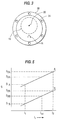
- Figure 3 is a schematic end-on view of the gauges of Figures 1 and 2.
- Figure 4 is a schematic block diagram of an illustrative gauge and controller in accordance with the invention.
- Figure 5 is an illustrative example of selected data shown in Table 1.
- Figures 6 and 7 are illustrative examples of calculated data.
- Figure 8 is a schematic end-on view of the gauges of Figure 1 or Figure 2 illustrating a further embodiment of the present invention utilizing a flat offset cathode with electron focusing means.
- Figure 9 is a schematic side view of the gauges of Figure 1 or Figure 2 illustrating another embodiment of the present invention.
- Figures 10a-10d are schematic cross-sectional views of different cylindrical electrode structures illustrating the effect on axial field components by different end cap configurations
- a nude gauge assembly 10 of the BA type in accordance with the present invention comprises a gas permeable, metallic shield 12 (which may be cylindrical in configuration), an open, metallic, insulator shield 14, a cathode or electron source 16, an anode 18 (which may also be cylindrical in configuration), a collector electrode 20, insulated vacuum feedthroughs 22, a vacuum enclosure 24, and a flange 28 to attach the gauge to the vacuum system.
- the shield 12 and the insulator shield 14 are preferably connected to each other and are preferably grounded and serve to define a shielded volume 26 wherein the electric charge distribution on the gauge surfaces is not disturbed by potentials external to shielded volume 26.
- shield 12 and insulator shield 14 may be considered a shield means or outer electrode which is at least partially open (mesh-like, for example) and which completely surrounds the cathode, anode and collector electrode disposed within shielded volume 26.
- the shield means is at least partially open to permit transfer of gas molecules in and out of the shielded volume.
- the shield means (and insulator shield 14, in particular) is at least partially open at 14' to permit electrical connections to the cathode, anode, and collector electrode so that the latter electrodes are electrically isolated from the shield means.
- any electrons or ions generated within the shielded volume which contact the shield means will be passed to ground while any potentials (which may be quite large depending on the process) external to the shielded volume will have no effect on the electric charge distribution on gauge surfaces within the shielded volume.
- stabilization of the gauge sensitivity is achieved in this first important respect. Means and procedures for obtaining further stabilization are described below.
- Figures 2 and 3 illustrate another embodiment of a non-nude (modest) gauge 32 wherein a metallic vacuum enclosure 24 serves the same function as longitudinally extending portion 12'' of the shield 12 in Figure 1.
- a metallic, gas permeable plasma shield 30 serves the same function as the end 12' of the shield 12 in Figure 1.
- the shield means includes vacuum envelope 24, plasma shield 30, and insulator shield 14 where, as in the Figure 1 embodiment, the shield means is preferably grounded.
- vacuum enclosure 24 is made of glass, on electrically conductive coating may be provided on the inner surface thereof to provide the function of portion 12'' of Figure 1.
- electrically conductive coating may be provided on the inner surface thereof to provide the function of portion 12'' of Figure 1.
- a screen grid may be provided between a glass vacuum enclosure where the screen would provide the function of portion 12'' of Figure 1.
- Other means for completely enclosing shielded volume will occur to those of ordinary skill in this art.
- the dimensions of the shield means are preferably maintained substantially the same in both embodiments.
- the locations of the cathode, anode, and collector electrode with respect to the shield means are substantially the same over time and from gauge to gauge so that there is no change in the electric charge distribution on surfaces within the shielded volume which would otherwise be caused by variations in the location of these elements with respect to the shield means.
- the location of the gauge electrode surfaces can be fixed over time in the same gauge and from gauge-to-gauge by utilizing good mechanical design and construction techniques which are well-known in the art of electron tube design and construction.
- the cathode as is known, can be prevented from sagging in use by utilizing a small spring to tension the cathode. Motion due to bimetallic joints can be avoided by proper joint design. Close tolerance electrode structures can readily be assembled using proper jigs and fixtures as is well-known in the art. Proper design of the feedthrough insulator as is well-known in the art insures that reasonable stresses applied to the feedthrough outside the gauge will not move the surfaces inside the gauge.
- illustrative controller circuitry in accordance with the present invention consists of a cathode heating power control 40 which maintains a constant emission current, i ⁇ , from the hot cathode, 16, in accordance with a pre-selected value stored in the parameter setting block 42. Also stored in block 42 is the gauge tube type, electrode voltages and gas type information which the user has pre-selected.
- a multiplexer 44 and an A/D converter, 46 digitizes the measured analog values of the ion collector current, i+, the cathode heating current i K , and the cathode heating voltage, V K .
- the collector current i+ may be uniquely utilized in the calibration technique of the present invention to compensate for the variation in gauge sensitivity S with pressure. Digitized values of i+ are supplied to the computation block 48 where this data is combined with generic pressure calibration information stored in memory 50. The correct value of S is calculated. Then the correct value of unknown pressure P x , in the gauge is calculated in block 48 and fed to the pressure display 52, for display.
- the cathode heating voltage and current may be uniquely utilized in the calibration technique of the present invention to compensate for varying characteristics of the cathode such as the work function thereof. Digitized values of the cathode heating voltage and current and the collector current i+ are supplied to the computation block 48 where this data is combined with generic pressure calibration information stored in memory 50. The correct value of S is calculated. Then the correct value of the unknown pressure P x , in the gauge is calculated in block 48 and fed to the pressure display, 52, for display.
- the above calibration methods and apparatus are preferably utilized with the gauge configurations of Figures 1-3 and equivalents thereof but may also be employed with other ionization gauges including BA gauges provided they are sufficiently stable.
- the foregoing calibration methods and apparatus can be utilized because of the high degree of stability of the sensitivity of the gauges of Figures 1-3 and equivalents thereof. That is, heretofore, due to the instability of the sensitivity of prior art gauges, it has not been practical to utilize the calibration methods and apparatus of the present invention.
- Generic pressure calibration data as shown in Table 1 is stored in memory. This data is preferably obtained by averaging measurements utilizing two or more (twenty, for example) BA ionization gauge systems in accordance with the present invention using known pressure calibration apparatus.
- data set A of Table 1 corresponds to low cathode heating powers needed to produce an electron emission current of 100 ⁇ A, data set B to medium cathode heating powers required to produce this emission current, and data set C to high cathode heating powers.
- i1, W 1A , and S 1A are the average collector current i, cathode heating power W, and sensitivity S of twenty (for example) gauges of the present invention for a first known calibration pressure; i2, W 2A , and S 2A are the average collector current, cathode heating power, and sensitivity for a second known calibration pressure greater than the first calibration pressure; etc.
- the number of calibration pressures will extend over the desired pressure measurement range.
- i, W, and S are obtained for the above series of calibration pressures for a plurality of different cathode heating powers required to obtain a predetermined emission current with slightly different degrees of contamination of the emitting surface of the cathode.
- data sat B will be selected to have cathode heating powers greater than those of data set A while data set C will be selected to have cathode heating powers greater than those of data set B.
- the cathode heating powers of data sets A, B, and C preferably extend over the range of expected cathode heating powers of gauges in actual use.
- the number of data sets may be changed to insure appropriate representation over the expected range of cathode heating powers.
- a gauge may be temporarily exposed to contamination such as oxygen from the system being monitored whereby the work function of the cathode will be increased to a certain extent depending upon the degree of exposure. With further usage of the gauge, the degree of change of work function may increase or decrease.
- the amount of cathode heating power required to obtain a predetermined amount of emission current will vary from gauge to gauge and over time with respect to a particular gauge. In accordance with the present invention, this variation in the cathode heating power can be compensated by utilizing calibration data typified by data sets A, B, and C.
- data sets A, B, and C respectively correspond to cathode heating powers required to obtain an emission current of 100 ⁇ A.
- 100 ⁇ A is a typical emission current utilized in measurements of high pressure ranges. In lower ranges, a larger emission current such as 1 ma is used and this is exemplified by data set D.
- data sets E and F which would respectively correspond to data sets B and C.
- Table 1 the number of data sets are required for expected pressures, gas types, emission currents and cathode heating powers can be obtained and employed in Table 1.
- gas type N2 is entered into the parameter settings block 42 by the user using a selector switch, for example.
- the controller 38 may be arranged to select the optimum value of emission current depending on the current value of the pressure in the gauge as is well-known in the art. This automatically selected value of i ⁇ is then fed to the parameter setting block 42.
- Parameter setting block 42 is also set for gauge type and electrode potentials applied.
- the controller circuitry has been previously programmed as is well known in the art to select the two data sets stored in memory 50 which most closely approximate the actual conditions existing during measurement of the unknown pressure P x .
- Note data sets A and B are selected since W x occurs between (a) W 1A where W 1A is the cathode heating power associated with the first calibration pressure and the low cathode heating power utilized during the calibration procedure and (b) W 2B where W 2B is the cathode heating power associated with the second calibration pressure and the medium cathode heating power.
- S XB can be calculated similarly.
- S XA and S XB are indicated on Figure 5.
- the cathode heating power W XB corresponding to any i +x can be calculated in computation block 48 according to the equation.
- (W XB -W 1B )/(W 2B -W 1B ) (i +x -i1)/(i2-i1) or by rearrangement
- W XB (W 2B -W 1B )(i +x -i1)/(i2-i1) + W 1B where all the terms on the right are known either from direct measurement or from data stored in memory 50.
- W XA can be calculated similarly.
- W XA and W XB are indicated on Figure 6.
- S x indicated on Figure 7 is the correct value of the gauge sensitivity corresponding to the actual conditions which existed when i +x was measured at the unknown pressure P x .
- This value of S x is then used in Eq. 3 to calculate the correct value of the unknown pressure P x which can then be displayed as is well known in the art.
- FIG 8 there is shown a metallic shield 12 corresponding to the shield 12 of Figure 1 (or to the shield 24 of Figure 2), an offset, axially extending, flat cathode 16, an optional axially extending electron focusing means 17, an axially extending anode 18 in the form of a substantially transparent grid with three support posts 50 extending axially along the anode 18 and an axially extending ion collector electrode 20.
- Flat cathode 16 is positioned so that the perpendicular to the cathode surface is directed at an imaginary axis 51 which is offset from the axis of the cylindrical anode 18 and the cylindrical ion collector 20.
- Such a configuration is disclosed in beforementioned U.S. Patent Application 07/507,579.
- flat cathode 16 may be so positioned and so biased that the electrons launched therefrom are initially in substantially parallel paths whereby such focusing thereof will result in substantially all of the emitted electrons following substantially the same trajectories within the anode volume defined by anode 18.
- Such a flat cathode which is so positioned and biassed is preferred in the present invention.
- focusing elements 17 may be optionally employed to effect the above mentioned initially substantially parallel paths of the emitted electrons. For example, if a non-flat cathode is employed or if the flat cathode is not properly positioned and/or biased, it may be desirable to employ focusing elements 17 which in cooperation with the cathode will effect the desired initially substantially parallel paths of the emitted electrons.
- the focusing elements 17 typically constitute electrodes, which in cooperation with cathode 16, generate electrostatic fields whereby, depending upon the potentials applied to the cathode and focusing elements, the electrons can be emitted in the desired initially substantially parallel paths.
- the conditions for such focusing can be readily determined utilizing known electromagnetic field theory.
- computer techniques for electron ray tracing which are well known in the design of electron microscopes, cathode ray tubes, image intensifiers, mass spectrometers, etc. may be utilized.
- the biasing of the focusing elements 17 and cathode 16 is such as to assure that all of the admitted electrons follow substantially the same trajectories through the anode volume defined by anode 18. More particularly, as will be further discussed below, most of the emitted electrons should be made to pass repeatedly through the anode volume before being collected on the anode. Thus, much longer electron path lengths are produced resulting in a much larger number of ions/second being formed at a given pressure.
- the term "electron source” as used in the following claims may mean either cathode 16 by itself where the cathode is preferably flat, as discussed above or cathode 16 in combination with focusing means 17.
- the support posts 50 are positioned so that the stream of electrons from the cathode 16 does not impinge on a support post 50 as the electron stream enters nor as the electron stream exits the anode volume 52.
- the transparency of the anode is optimized at these areas where the electron stream passes through the anode.
- axially extending slits may be provided in the anode at these areas to further optimize the transparency of the anode thereat.
- Applicants have found by computer simulation and by actual test that when the support posts 50 are positioned so that a portion of the electron stream impinges on a support post 50 either upon entering or exiting the anode volume 52 that the accuracy of the gauge reading fluctuates uncontrollably with time in a given gauge and from gauge to gauge.
- metallic shield 24 ( Figure 2) which may be the vacuum tubulation in which the gauge structure is housed, a metallic shield 30 which is gas permeable, a metallic insulator shield 14 which has openings to permit supports for the cathode 16, the anode 18, and the ion collector 20 to pass through as described hereinbefore.
- Partial end caps 53 and 54 are provided to reduce end effects.
- the ion collector 20 is extended as close as practically possible to the shield 30.
- the emitting portion of the cathode 15 is approximately centered axially on the anode 18 and extends axially in each direction no further than where the electric field within the anode 18 begins to have a significant axial field component, as discussed below.
- FIG 10 schematic cross-sectional views of cylindrical electrode structures are shown together with one representative equipotential contour.
- the ends of the anode 18 are open and the equipotential contour 57 is hour glass shaped.
- the end cups 55 and 56 on the anode completely clone off the ends of the anode 18 electrically except for a small hole to permit the ion collector to pass through end cap 56.
- the equipotential contour 58 is barrel shaped.
- Figure 10c an important feature of the present invention is illustrated.
- Partial end caps 53 and 54 on the anode 18 are provided so that the equipotential contour 59 within the anode 18 tends to have the same radius almost to the ends of the anode 18, thus closely approximating the equipotentials 60 which exist in the infinitely long co-axial cylinders 18 and 20 illustrated in Figure 10d.
- a longer cathode can be utilized and still have the electrons injected into the anode volume where significant axial fields are not present.
- Figures 8-10 together with the features of Figures 1-7, function as a whole to provide significantly improved repeatability, measurement to measurement, and reproducibility, gauge to gauge, although it is to be understood the Figure 8-10 features do not necessarily need to be employed with the features of Figures 1-7 to obtain significant improvements. Improvements in accuracy of pressure measurement of the order of tenfold have been repeatedly produced using these new features.
- the collector 20 may be located on axis 51 while the cathode 16 may be located in line (rather than offset) with respect to the axis of the anode.
- the relative locations illustrated in Figure 8 are preferred inasmuch as a central location of the collector will promote uniformity of the electron paths.
- the present invention avoids the problem of a higher x-ray limit by causing the collected ion current at a given low pressure to be increased by at least the same amount that the x-ray current is increased due to the larger surface area of the ion collector 20. Accordingly, the ratio of x-ray current to collected ion current and hence the x-ray limit is not increased in the present invention even though the ion collector 20 diameter is at least 400% larger than in prior art BA gauges.
- ion collector diameters from about 0.015 in to about 0.080 in. and preferably about 0.020 in. to about 0.060 in. yield improved accuracy without adversely affecting the x-ray limit in the present invention.
- the use of as long an ion collector 20 as possible also helps to reduce the length of the region where there are significant axial electric field components.
- a spacing of about 0.050 in. between the end of the ion collector 20 and the shield 12' produces good results.
- the collector should preferably at least extend beyond the end cap 53, as illustrated in Figure 9.
- Axial electric field components within the anode volume tend to cause ions to escape axially and not be collected on the ion collector 20.
- the escape of, say, 10% to 20% of the ions formed would not in itself be greatly disadvantageous if the fraction escaping remained constant.
- the electron emission density varies uncontrollably along the length of the cathode 16, as is well-known in the art, the number of ions/sec formed in the end zones of the anode 18 varies uncontrollably with time. Thus, the accuracy of measurement is seriously affected it ions are formed in regions of the anode 18 where there are significant axial electric field components.
- partial end caps 53 and 54 By utilizing partial end caps 53 and 54, axial electric field components in the anode volume can be significantly reduced except at the very ends of the anode 18. Thus, accuracy of measurement is significantly improved by utilizing partial end caps 53 and 54 where the end caps extend radially inward at least about 25% of the radius of the anode but not more than about 75% of this radius.
- the uniformity of transparency of the anode 20 in the regions where the electron stream from the hot cathode 16 passes through the grid which forms the anode 20 is also important to achieve good accuracy. If the transparency of the anode 20 to the passage of electrons varies from point to point, then minor changes in the trajectory of the electrons can seriously affect the fraction of electrons entering or leaving the anode volume. Thus, by providing uniform transparency of the anode insofar as possible, accuracy of measurement is improved, as discussed hereinbefore with respect to support posts 50.
Landscapes
- Physics & Mathematics (AREA)
- General Physics & Mathematics (AREA)
- Measuring Fluid Pressure (AREA)
Applications Claiming Priority (4)
| Application Number | Priority Date | Filing Date | Title |
|---|---|---|---|
| US778371 | 1985-09-20 | ||
| US07/778,371 US5250906A (en) | 1991-10-17 | 1991-10-17 | Ionization gauge and method of using and calibrating same |
| US07/906,665 US5296817A (en) | 1990-04-11 | 1992-06-30 | Ionization gauge and method of using and calibrating same |
| US906665 | 2001-07-18 |
Publications (2)
| Publication Number | Publication Date |
|---|---|
| EP0537770A2 true EP0537770A2 (de) | 1993-04-21 |
| EP0537770A3 EP0537770A3 (en) | 1993-07-28 |
Family
ID=27119439
Family Applications (1)
| Application Number | Title | Priority Date | Filing Date |
|---|---|---|---|
| EP19920117733 Withdrawn EP0537770A3 (en) | 1991-10-17 | 1992-10-16 | Ionization gauge and method of using and calibrating same |
Country Status (3)
| Country | Link |
|---|---|
| US (1) | US5296817A (de) |
| EP (1) | EP0537770A3 (de) |
| JP (2) | JP3359941B2 (de) |
Cited By (4)
| Publication number | Priority date | Publication date | Assignee | Title |
|---|---|---|---|---|
| CN101726390B (zh) * | 2008-10-14 | 2014-01-29 | 安立世公司 | 用于电离真空计的分子屏 |
| CN106206237A (zh) * | 2016-08-31 | 2016-12-07 | 兰州空间技术物理研究所 | 一种高灵敏度的碳纳米管阴极电离规 |
| CN106404277A (zh) * | 2008-09-19 | 2017-02-15 | Mks仪器公司 | 具有发射电流及偏压电位控制的电离计 |
| CN111678642A (zh) * | 2020-05-29 | 2020-09-18 | 中国航发南方工业有限公司 | 一种热阴极电离真空计发射电流测试装置及方法 |
Families Citing this family (19)
| Publication number | Priority date | Publication date | Assignee | Title |
|---|---|---|---|---|
| US5422573A (en) * | 1990-04-11 | 1995-06-06 | Granville-Phillips Company | Ionization gauge and method of using and calibrating same |
| US5655886A (en) * | 1995-06-06 | 1997-08-12 | Color Planar Displays, Inc. | Vacuum maintenance device for high vacuum chambers |
| US5801535A (en) * | 1996-11-12 | 1998-09-01 | Granville-Phillips Company | Ionization gauge and method of using and calibrating same |
| CA2288798A1 (en) | 1997-05-09 | 1998-11-12 | The Fredericks Company | Bayard-alpert vacuum gauge with neutralization of x-ray effect |
| US6025723A (en) | 1997-08-27 | 2000-02-15 | Granville-Phillips Company | Miniature ionization gauge utilizing multiple ion collectors |
| US6081121A (en) * | 1998-01-21 | 2000-06-27 | Helix Technology Corporation | Ionization gauge and method of using and calibrating same |
| US6313547B1 (en) | 2000-03-09 | 2001-11-06 | Umm Electronics, Inc. | Apparatus for quality control verification of an electrochemistry test |
| US6756785B2 (en) * | 2002-07-25 | 2004-06-29 | Mks Instruments, Inc. | Pressure controlled degas system for hot cathode ionization pressure gauges |
| CN1965219A (zh) * | 2004-03-12 | 2007-05-16 | 布鲁克斯自动化有限公司 | 电离真空计 |
| US7313966B2 (en) * | 2004-12-14 | 2008-01-01 | Brooks Automation, Inc. | Method and apparatus for storing vacuum gauge calibration parameters and measurement data on a vacuum gauge structure |
| EP1698878A1 (de) * | 2005-03-04 | 2006-09-06 | Inficon GmbH | Elektrodenanordnung und Druckmessvorrichtung |
| US7456634B2 (en) | 2006-10-26 | 2008-11-25 | Brooks Automation, Inc. | Method and apparatus for shielding feedthrough pin insulators in an ionization gauge operating in harsh environments |
| JP5148104B2 (ja) * | 2006-12-20 | 2013-02-20 | 株式会社アルバック | 真空測定方法および真空計 |
| JP2008232665A (ja) * | 2007-03-16 | 2008-10-02 | Fujifilm Corp | 圧力解析システム |
| US7768267B2 (en) * | 2007-07-11 | 2010-08-03 | Brooks Automation, Inc. | Ionization gauge with a cold electron source |
| JP5054226B2 (ja) | 2009-03-18 | 2012-10-24 | 株式会社アルバック | 酸素の検出方法,空気リークの判別方法,ガス成分検出装置,及び真空処理装置 |
| CN103311085B (zh) * | 2013-06-27 | 2016-03-16 | 成都国光电气股份有限公司 | 一种小型化复合真空规管 |
| US10242855B1 (en) * | 2016-09-21 | 2019-03-26 | The United States of America as requested by the Secretary of the Air Force | Detector, system and method for droplet and/or cluster beam spectroscopy |
| EP3998467B1 (de) * | 2019-09-13 | 2024-01-03 | Canon Anelva Corporation | Ionisationsvakuummeter und kartusche |
Family Cites Families (13)
| Publication number | Priority date | Publication date | Assignee | Title |
|---|---|---|---|---|
| US3356287A (en) * | 1965-07-28 | 1967-12-05 | Granville Phillips Company | Method and apparatus for ion pumping and pressure measurement |
| US3495165A (en) * | 1967-02-13 | 1970-02-10 | Gen Electric | Vacuum device gas measurement apparatus and method |
| US3743876A (en) * | 1969-10-07 | 1973-07-03 | Canadian Patents Dev | Hot-cathode ionization gauge having electrode means for shaping the electric field in the vicinity of the cathode |
| GB1336126A (en) * | 1969-10-29 | 1973-11-07 | Mullard Ltd | Ion gauges |
| US3839655A (en) * | 1973-08-24 | 1974-10-01 | Varian Associates | Bayard-alpert vacuum ionization tube |
| FR2454696A1 (fr) * | 1979-04-18 | 1980-11-14 | Anvar | Dispositif du genre orbitron, muni de plateaux d'extremite |
| US4307323A (en) * | 1980-04-04 | 1981-12-22 | Granville-Phillips Company | Vacuum gauge |
| DE3042172A1 (de) * | 1980-11-08 | 1982-06-16 | Leybold-Heraeus GmbH, 5000 Köln | Ionisationsmanometerroehre nach bayard-alpert |
| US4714891A (en) * | 1985-09-23 | 1987-12-22 | Granville-Phillips Company | Method and apparatus for improving the safety and extending the range of ionization gauge systems |
| JPS62218834A (ja) * | 1986-03-20 | 1987-09-26 | Seiko Instr & Electronics Ltd | 気体圧力計 |
| DE3628847C2 (de) * | 1986-08-25 | 1995-12-14 | Max Planck Gesellschaft | Heißkathoden-Ionisationsmanometer |
| US4902977A (en) * | 1989-01-10 | 1990-02-20 | University Of Utah | Multipactor pressure gauge for use as a noninvasive vacuum tube sensor |
| US5128617A (en) * | 1990-04-11 | 1992-07-07 | Granville-Phillips Company | Ionization vacuum gauge with emission of electrons in parallel paths |
-
1992
- 1992-06-30 US US07/906,665 patent/US5296817A/en not_active Expired - Lifetime
- 1992-10-16 EP EP19920117733 patent/EP0537770A3/en not_active Withdrawn
- 1992-10-19 JP JP28029392A patent/JP3359941B2/ja not_active Expired - Lifetime
-
2002
- 2002-07-30 JP JP2002221450A patent/JP3434813B2/ja not_active Expired - Fee Related
Cited By (4)
| Publication number | Priority date | Publication date | Assignee | Title |
|---|---|---|---|---|
| CN106404277A (zh) * | 2008-09-19 | 2017-02-15 | Mks仪器公司 | 具有发射电流及偏压电位控制的电离计 |
| CN101726390B (zh) * | 2008-10-14 | 2014-01-29 | 安立世公司 | 用于电离真空计的分子屏 |
| CN106206237A (zh) * | 2016-08-31 | 2016-12-07 | 兰州空间技术物理研究所 | 一种高灵敏度的碳纳米管阴极电离规 |
| CN111678642A (zh) * | 2020-05-29 | 2020-09-18 | 中国航发南方工业有限公司 | 一种热阴极电离真空计发射电流测试装置及方法 |
Also Published As
| Publication number | Publication date |
|---|---|
| JPH05203524A (ja) | 1993-08-10 |
| JP3434813B2 (ja) | 2003-08-11 |
| JP3359941B2 (ja) | 2002-12-24 |
| EP0537770A3 (en) | 1993-07-28 |
| JP2003050176A (ja) | 2003-02-21 |
| US5296817A (en) | 1994-03-22 |
Similar Documents
| Publication | Publication Date | Title |
|---|---|---|
| US5422573A (en) | Ionization gauge and method of using and calibrating same | |
| US5296817A (en) | Ionization gauge and method of using and calibrating same | |
| US5250906A (en) | Ionization gauge and method of using and calibrating same | |
| EP0233784B1 (de) | Vakuumüberwachungsvorrichtung | |
| Molnar | Studies of γ-processes of electron emission employing pulsed townsend discharges on a millisecond time scale | |
| JPH07181095A (ja) | 電離真空計 | |
| Arnold et al. | Stable and reproducible Bayard–Alpert ionization gauge | |
| JP3069975B2 (ja) | 電離真空計 | |
| US3839655A (en) | Bayard-alpert vacuum ionization tube | |
| US3001128A (en) | Measuring | |
| CN112582247A (zh) | 一种用于囚禁离子的小型真空装置和方法 | |
| US3267326A (en) | Vacuum gauge | |
| US4307323A (en) | Vacuum gauge | |
| Gentsch et al. | An improved ion gauge with gold coated electrodes for reliable operation in reactive gases and for use as reference standard | |
| US3239715A (en) | Electron emission monitor for magnetron-type ionization gauge | |
| US2852694A (en) | Ionization chamber | |
| US3387175A (en) | Vacuum gauge having separate electron collecting and electron accelerating electrodes | |
| US3320455A (en) | Ionization vacuum gauge having x-ray shielding means | |
| US6257069B1 (en) | Bayard-alpert vacuum gauge with neutralization of x-ray effect | |
| US2963601A (en) | Ionization vacuum gauge | |
| Jousten | Ultrahigh vacuum gauges | |
| US3254256A (en) | Ionization vacuum gauge having an emissive electrode support means | |
| US3071704A (en) | Gauge | |
| Jousten | Pressure measurement with ionization gauges | |
| Arnold et al. | Causes of unstable and nonreproducible sensitivities in Bayard–Alpert ionization gauges |
Legal Events
| Date | Code | Title | Description |
|---|---|---|---|
| PUAI | Public reference made under article 153(3) epc to a published international application that has entered the european phase |
Free format text: ORIGINAL CODE: 0009012 |
|
| AK | Designated contracting states |
Kind code of ref document: A2 Designated state(s): DE FR GB |
|
| PUAL | Search report despatched |
Free format text: ORIGINAL CODE: 0009013 |
|
| AK | Designated contracting states |
Kind code of ref document: A3 Designated state(s): DE FR GB |
|
| 17P | Request for examination filed |
Effective date: 19940125 |
|
| 17Q | First examination report despatched |
Effective date: 19950210 |
|
| STAA | Information on the status of an ep patent application or granted ep patent |
Free format text: STATUS: THE APPLICATION IS DEEMED TO BE WITHDRAWN |
|
| 18D | Application deemed to be withdrawn |
Effective date: 19970617 |