EP0538056A2 - Bildverarbeitungssystem - Google Patents
Bildverarbeitungssystem Download PDFInfo
- Publication number
- EP0538056A2 EP0538056A2 EP92309476A EP92309476A EP0538056A2 EP 0538056 A2 EP0538056 A2 EP 0538056A2 EP 92309476 A EP92309476 A EP 92309476A EP 92309476 A EP92309476 A EP 92309476A EP 0538056 A2 EP0538056 A2 EP 0538056A2
- Authority
- EP
- European Patent Office
- Prior art keywords
- data
- image
- frame
- image processing
- groups
- Prior art date
- Legal status (The legal status is an assumption and is not a legal conclusion. Google has not performed a legal analysis and makes no representation as to the accuracy of the status listed.)
- Granted
Links
Images

Classifications
-
- H—ELECTRICITY
- H04—ELECTRIC COMMUNICATION TECHNIQUE
- H04N—PICTORIAL COMMUNICATION, e.g. TELEVISION
- H04N9/00—Details of colour television systems
- H04N9/79—Processing of colour television signals in connection with recording
- H04N9/797—Processing of colour television signals in connection with recording for recording the signal in a plurality of channels, the bandwidth of each channel being less than the bandwidth of the signal
- H04N9/7973—Processing of colour television signals in connection with recording for recording the signal in a plurality of channels, the bandwidth of each channel being less than the bandwidth of the signal by dividing the luminance or colour component signal samples or frequency bands among a plurality of recording channels
-
- G—PHYSICS
- G06—COMPUTING OR CALCULATING; COUNTING
- G06T—IMAGE DATA PROCESSING OR GENERATION, IN GENERAL
- G06T1/00—General purpose image data processing
- G06T1/60—Memory management
-
- H—ELECTRICITY
- H04—ELECTRIC COMMUNICATION TECHNIQUE
- H04N—PICTORIAL COMMUNICATION, e.g. TELEVISION
- H04N5/00—Details of television systems
- H04N5/76—Television signal recording
- H04N5/91—Television signal processing therefor
Definitions
- the present invention relates to an image processing system.
- a video graphics system is described in our British Patent no. 2,089,625 and corresponding United States Patent no. 4,514,818, the teachings of which are incorporated herein by reference.
- This system includes a touch tablet and stylus combination for generating position signals designating the position of the stylus relative to the touch tablet.
- the user or operator paints or draws (hereinafter referred to simply as "paints") by selecting a colour and a so called brush distribution from a range of predefined colours and distribution functions. Movement of the stylus relative to the touch tablet causes the generation of a series of position signals.
- the system also includes a pixel processing circuit and a frame storage means which can store an array of pixels representing a picture.
- a patch of pixels in the frame storage means referenced by each designated position is modified in response to the selected colour and distribution. All the pixels in the frame storage means, representing the picture, can moreover be read repeatedly and applied to a monitor to display the picture as it is built up by the operator.
- the monitor should display the build-up of the picture virtually in real time, which means in practice that the processing of all the patches of pixels which may be identified by position signals in a frame period should be completed, and the pixels written in the picture store (without interfering with reading from the store to the monitor) also within a frame period, at least when the time is averaged over a few frame periods.
- the number of pixels to be processed is dependent on the number of picture points required per unit of picture area, that is to say on the resolution of the system; if the resolution is increased, the number of position signals generated for a given movement of stylus, or in a given time interval is also increased, as is the number of pixels in a given brush patch.
- Real time processing can usually be achieved in systems operating to television standards, including even the high definition standard of 1250 lines per field at 50 fields per second, or 1125 lines/60 fields, though difficulties are encountered as the resolution, and hence the amount of data that is required to be manipulated, increases.
- the framestore is arranged to receive new image data created by a processor in response to user manipulations of a stylus/touch tablet device.
- the framestore and the viewing store both have the capacity to store a high definition image and to facilitate display of the image on a high definition monitor the framestore is arranged to transfer only portions of its data contents to the viewing store during a frame period. The portion transferred is determined by the position of the stylus on the touch tablet at the beginning of a frame period.
- Data in the viewing store is output in raster sequence for display on the monitor.
- the control image usually comprises areas of pixels having a maximum value which represents opacity and a minimum value which represents transparency and is created so that in effect it masks a selected part of the foreground image while exposing the remainder.
- the control image is defined by eight bits and during creation can be displayed as a single color superimposed on the foreground picture.
- First address means are moreover provided for reading the pixels of the foreground image and the control image in parallel from the respective parts of the storage means and applying them to a linear interpolating circuit, which is rendered operational during an image preview mode and during an image composition mode.
- a second address means provides the pixels in the background image also to the two interpolating means concomitantly with the reading of the foreground image pixels and the control image pixels.
- the first address means is connected to a manipulator which, under stylus control or the control of other user operable means, can change the order of reading the foreground pixels and control pixels relative to the background pixels so as to effect a spatial transformation of the foreground and stencil relative to the background. Whilst the system is in preview mode, the artist can manipulate the stylus or other control means to effect a series of desired transformations such as zoom, pan, scroll, rotate, and change perspective. During a frame period the foreground image pixels in transformed order and the background image pixels are applied to the input of the first interpolating means whilst the control image is applied to a control input to act as a pixel-by-pixel interpolating coefficient.
- the output of the interpolating means is applied to the picture monitor and displayed, but without affecting any of the pictures as stored.
- the interpolation has the effect of causing the display to represent the foreground image where the control image is opaque and to represent the background image where the control image is transparent, simulating the pasting or overlaying of the part in the foreground image on the background.
- the stylus or control means to vary the spatial transformation, the artist can try various positions of the insert onto the background image from the foreground image until he perceives a desired transformation. Thereupon the artist, by producing a predetermined "stick" command, switches the system to the composition mode.
- the foreground image pixels and background image pixels are then read to the second interpolating means and interpolated under control of the control image pixels, the foreground image and control image pixels being read in the transformation order prescribed in the last try during the preview mode.
- the present invention aims to overcome or at least reduce the above mentioned and associated problems and aims to provide a system capable of manipulating large amounts of image data apparently instantaneously.
- an image processing system in which data defining a plurality of picture elements which together represent at least one image frame of a given resolution are divided into data groups which are distributed among respective independent storing units, the data forming each group defining a lower resolution representation of the entire image frame.
- a method of storing data representing an image in which method data defining a plurality of picture elements in a plurality of lines which together represent at least one image frame is stored in a distributed store comprising plural independent storing devices, the method comprising switching selected pixels from each line and switching selected lines from the or each frame to respective ones of said storing devices such that the image data is divided into groups which each define a representation of substantially the entire image at a lower resolution than that of the image frame.
- an image processing system comprising a memory for storing data representing at least one image frame; a framestore for temporarily storing at least one frame of image; a processor for processing said data in said framestore to produce modified data representing a version of said image; and means associated with said memory for dividing said data into groups which are stored separately in said memory, each group defining a lower resolution version of substantially the whole of said image.
- a video processing system comprises eight bulk stores 1 to 8 arranged in pairs for storing data representing plural video frames which together form one or more video sequences.
- the bulk stores are disk stores and each disk store pair has a respective buffer 9 to 12 for controlling the transfer of data to and from the stores.
- the disk stores 1 to 8 are typically capable of storing data representing up to 2230 frames of video at a resolution of 2880 pixels by 2080 lines per frame, that is, four times the resolution of a typical high definition television (HDTV) standard of 1440 pixels by 1040 lines per frame.
- HDTV high definition television
- Video data may be stored in the disk stores in any suitable format, for example RGB or YUV. In this example it is assumed that the data is stored in YUV format. Each frame is distributed among the disk stores 1 to 8 in a manner to be described in greater detail herein below.
- the buffers 9 to 12 output luminance (Y) data to a luma switch 13 and output chrominance (U,V) data to a chroma switch 14.
- the luma switch 13 and the chroma switch 14 cooperate to combine respective chrominance and luminance data for supply to a manipulation framestore 15, comprising two individual framestores each 24 bits deep.
- the manipulation framestore 15 has sufficient storage locations to store data representing two complete YUV image frames each comprising 2880 pixels by 2080 lines, together with a respective key or control image, 8 bits deep.
- Each of the individual framestores is moreover multi-ported, so that irrespective of any manipulation of pixels which may be occurring in a respective store, the store in use is read serially via a processor 16 into a display framestore 17.
- the system can also be conditioned for display of control images or key signals held in the manipulation framestore 15, either separately in monochrome or superimposed on its respective colour image frame.
- Image data in the display framestore 17 is at the lower HDTV resolution and is created by selectively transferring only selected data from the manipulation framestore 15 currently in use.
- Data from the display framestore 17 is read in raster sequence to a buffer 18 which converts it into analogue signals for display of the video on an HDTV monitor 19.
- the display framestore 17 is continually updated with the particular video frame (and/or key or control signal) being manipulated at a particular time. Before such a manipulation occurs the respective frame with or without a key or control signal is transferred from the disks 1 to 8 to the framestore as above indicated via the switches 13 and 14 at the appropriate rate, say 54 MHz. After the manipulation has been completed to the satisfaction of the operator, the colour image and/or key or control image is transferred from the manipulation framestore 15 back to the bulk storage provided by the disks 1 to 8, the switches 13 and 14 during this transfer working in reverse sense.
- the system further comprises a stylus/touch tablet device 20 which outputs position signals XY relating to the position of the stylus in relation to the touch tablet when the stylus is brought into the proximity of the touch tablet.
- position signals XY relating to the position of the stylus in relation to the touch tablet when the stylus is brought into the proximity of the touch tablet.
- a signal relating to the pressure applied by the stylus is also output from the stylus/touch tablet device 20.
- the position signals X Y and the pressure signals are delivered via respective stores 21, 22 to the processor 16.
- the system shown in Figure 1 may be configured to operate as a painting system in order to effect changes to one or more frames in a stored video sequence.
- the operator is free to choose from a wide range of painting and other image modifying functions which are predefined in the systems.
- the operator may select a brush from a range of painting implements pre-defined in a brush store 23 and may select a colour to paint with the brush; data representing the selected colour being held in a colour store in known manner.
- the selected brush may then be used to retouch part of a frame with the selected colour.
- This is achieved by making the processor 16 responsive to the stylus and touch tablet to perform a read-modify-write operation on the selected frame data held in the manipulation framestore 15.
- the display framestore 17 is continually updated with data from the manipulation framestores 15 under the control of the processor 16.
- the two individual 24 bit framestores of the manipulation framestore 15 are connected to the processor 16 via respective lines 15a and 15b.
- One of the lines allows random access reading and writing from and to the storage locations within the manipulation framestore and is used by the processor 16 in executing the above mentioned read-modify-write operation.
- the arrangement also allows independent reading of the data in serial display order and is used by the processor 16 to update continually the display framestore 17.
- the processor 16 in fact comprises two independent processing units one dedicated to the read-modify-write drawing function and the other to the transfer of pixels for display.
- the processing unit of the processor 16 associated with the display is arranged to be transparent to only every other pixel and every other line of pixels in an image from the framestore 15 so that in effect every second pixel in both the horizontal and vertical direction is dropped from the picture before it is displayed on the HDTV monitor 19.
- Modification of data in the manipulation framestore 15 is effected in real time or substantially real time when spread over several frame periods. Such modification at the rate required for the high resolution picture (2880 x 2080) is made possible by employing, in the read-modify-write processing unit of the processor 16, the fast processing techniques described in our European Patent Application no. 90304116.8 published as EP-A-0403054 and corresponding US application 510,162, the teachings of which are incorporated herein by reference. Since the display framestore 17 is continuously updated with data from the manipulation framestore 15, the image that is displayed on the monitor 19 is such that the operator may see the effect of his modifications apparently instantaneously as he manipulates the stylus on the touch tablet. Once modifications satisfactory to the operator have been made to the selected picture, the modified pixel data is written back to the disk stores 1 to 8 in a manner that will be described in greater detail hereinafter.
- the system may also be employed to create a stencil or stencils to control the combining of single foreground and background images or of successive foreground and background images in a video sequence or clip.
- This facility is well known and is therefore not described in any further detail herein.
- An image frame of 2880 pixels by 2080 lines comprises 5,990,400 picture elements and one problem with handling picture data at this level of resolution is that it is difficult, using presently available technology, to store the data in bulk storage devices or handle the data for editing or other purposes, in real time.
- the system shown in Figure 1 is arranged to employ a unique manner of organising image frame data in the disk stores 1 to 8.
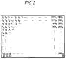
- a single high resolution image frame comprises an array of picture elements starting in the top left hand corner with the first pixel in the first row, picture element 11, and finishing in the bottom right hand corner with the 2880th pixel in the 2080th row, picture element 28802080.
- the frame is read serially to the luma and chroma switches 13, 14 a line at a time.
- the switches 13 and 14 distribute the pixels via the buffers 9 to 12 to different ones of the disk stores 1 to 8 and to respective divisions in the stores.
- reading of the data from the manipulation framestore 15 is arranged such that the image frame data is separated into two interleaved fields, one comprising the odd numbered lines and the other comprising the even numbered lines.
- the pixels in the lines are divided into two groups in order to halve the horizontal resolution of the image defined by each of the groups.
- One group of pixels comprises, in the case of the luma switch 13, all the odd numbered pixels in each line and the other group of pixels comprises all the even numbered pixels.
- one group comprises alternative chroma pixel pairs (UV) and the other group comprises the interleaving chroma pairs.
- data output from the switches comprises four interleaved sets of data.
- one set comprises alternate pixels in every odd line
- a second set comprises alternate pixels in every even line
- a third set comprises the intervening pixels in the odd lines
- a fourth set comprises the intervening pixels in the even lines. All groups relate to the same frame.
- the chroma pixels are similarly divided except that pixel pairs are involved instead of individual pixels.
- Each set of data therefore is a lower resolution version of the data in the framestore 15 and thus represents an image of a resolution similar to that of the monitor 19.
- the buffers 9 to 12 each participate in a further division of the data as the data is written to the disk stores 1 to 8.
- the transfer of data between each of the buffers and their respective disk stores can be likened to that of a multiplexer or commutator in that for each line of data received by a buffer, e.g. buffer 11, the first pixel is delivered to a first area in a first respective disk, e.g. disk 5, the second to a second area in a second respective disk, e.g. disk 6, the third to a third area in the first respective disk and the fourth to a fourth area in the second respective disk.
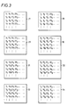
- disk store 1 say, receives an odd sub-field 27 and an even subfield 28 both containing pixels numbered 1, 9, 17, 25, etc. in each line.
- disk store 2 receives odd and even sub-fields 29 and 30 containing pixels 3, 11, 19, 27, etc..
- the chroma signals for each pixel are stored in one disk, eg disk 1, and the luma signals are stored in the other disk, eg disk 2.
- An advantage of adopting this approach of dividing the data into sub-fields is that it places the data in a form in which it can be readily retrieved and reformed into a higher resolution image by interleaving the sub-fields to make the data suitable for writing in raster order in the framestores 15 and for display of image on a raster type display. Pairs of groups of stored data which define a picture can be displayed directly on the monitor without further alteration, since the data is already defined as two interleaved fields.
- data from sub-fields 27 and 31 in Figure 3 could be combined to produce data for an image containing every fourth pixel in every other line or sub-fields 27, 29, 31 and 33 could be combined to produce an image containing every other pixel frog every other line.
- the data in each group of four subfields, eg sub-fields 27, 29, 31, 33 is at the correct resolution for display on the HDTV monitor, namely 1440 pixels by 1040 lines and so no data compression or expansion is required prior to display of the image.
- the system Shown in Figure 1 is thus such that image data from the disk stores for selected subfields, eg sub-fields 27, 29, 31, 33 in Figure 3, can written directly into the display framestore 17 by suitable control of the addressing of the disk stores 1 to 8 and buffers 9 to 12.
- the manipulation framestore 15 can be loaded with reduced size non-overlapping versions of a number of pictures in the bulk store to facilitate or plan the editing processing.
- Processor 16 may be transparent during this operation.
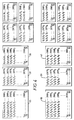
- the image frame of Figure 2 is first divided vertically into two fields, namely an odd field 35 comprising all pixels in all odd numbered lines of the frame, and an even field 36 comprising all even numbered lines of the frame.
- each field is divided horizontally into two groups comprising respectively lines of odd and even numbered pixels.
- the odd field 35 is divided into one group 37 comprising all odd numbered pixels on all odd numbered lines and another group 38 comprising all even numbered pixels on all odd numbered lines.
- the even field 36 is divided into one group 39 comprising all odd numbered pixels on all even numbered lines and another group 40 comprising all even numbered pixels on all even numbered lines.
- Each group 37, 38, 39, 40 comprises pixels which together represent the whole image.
- the number of pixels both horizontally and vertically in each group 37 to 40 is half that of the image frame of Figure 2 and, thus, each group contains one quarter of the information in the image frame.
- Each group 37 to 40 is of a size (1040 lines of 1440 pixels) suitable for display directly on the HDTV monitor 19.
- the data is again divided horizontally to form a set of eight subfields 41 to 48 so that each sub-field comprises either alternate odd numbered lines or alternate even numbered lines and therefore corresponds to either an odd or an even field of the low (HDTV) definition image defined by the data in the respective group 37 to 40.
- Figure 4 shows, for the purpose of explanation, the data being divided in several stages from a single frame into the eight sub-fields 41 to 48 much of the data division is achieved simply by controlling the order in which the data is addressed to the buffers 9 to 12.
- As data is read from the framestore 15 all odd numbered lines of data are delivered to buffers 9 and 10 and all even numbered lines of data to buffers 11 and 12. Buffers 9 and 11 then accept all odd numbered pixel data from the lines of data delivered to them respectively and similarly buffers 10 and 12 accept data corresponding to all even numbered pixels.
- the data is divided directly from the complete frame as shown in Figure 2 into the four groups 37 to 40.
- the final division into the eight sub-fields 41 to 48 is achieved by arranging the buffers to alternate the writing of each received line of data between its two associated stores.
- each group 37 to 40 is delivered to a respective buffer for storage in a respective disk pair it is easy to retrieve a group quickly from the disk stores, e.g. for display on the monitor 19.
- each group or sub-field defines a lower resolution representation of the entire image as compared to the representation of the image defined the complete frame of data.
- the data comprising each group or sub-field is selected such that horizontal or vertical lines of data from two or more of the groups or sub-fields can be interleaved to create a representation of the image at a higher resolution than that of the image as represented by the data in a single group or sub-field.
- the system of Figure 1 may be employed to combine a first or foreground video clip with a second or background video clip.
- the processor 16 comprises a menu generator (not shown) which is operable under user control to display a menu of user selectable options in a lower portion of the monitor 19.
- a menu generator (not shown) which is operable under user control to display a menu of user selectable options in a lower portion of the monitor 19.
- the user By selecting an editing mode the user conditions the system to operate as a video editing facility as described for example in our British Patent number 2113950.
- up to 2230 frames of video data can be individually stored and retrieved from the disk stores 1 to 8.
- the 2230 frame locations are divided into blocks or groups of locations under user control.
- the first clip of video is stored in a first block of frame locations and the second clip is stored in a second block of frame locations.
- a third block is assigned to the sequence of keying frames to be used to control the combining of the two clips and a fourth block is reserved for storing the resulting combined video clip.
- the sequence of keying frames may be created automatically, such as for example a chroma key, or each keying frame may be built up individually for each of the frames in the first or second clip using any of the many well known techniques now available.
- the system is arranged so that the user can step through the combined clip, before the two clips are finally combined, to preview the result of the combining and effect changes to the keying signal before the final combination is made.
- a foreground frame and the corresponding background frame from the disk stores 1 to 8 are transferred to the manipulation framestore 15. Thereafter, the data for the two images is read via lines 15a and 15b to the processor 16 where it is combined under the control of the corresponding keying frame.
- the resulting combined frame is transferred to the display framestore 17 for display of the result on the monitor 19.
- Each frame of the resulting combined sequence can be displayed in this way.
- the combined sequence could be displayed at up to the full speed of the sequence, eg 25 frames per second.
- this preview mode data is required at HDTV resolution for display on the monitor 19. Because of the manner in which the data for each frame of the clips is stored there is no need to read all of the high resolution data for each frame from the disk stores 1 to 8. Instead, data for the clips is transferred only from selected sub-fields in a similar manner to that previously described herein in respect of a single frame, the combining during preview being restricted to the reduced resolution images.
- This method of reading data from the disk stores 1 and 2 when the system is in the preview mode substantially reduces the amount of information required to be moved around the system. As a result, individual video frames and control image frames can be read from respective blocks of the stores 1 to 8, modified and combined by the processor 16, and the result displayed on the monitor 19.
- the user may experiment with the keying of the two clips for example, modify the or each keying frame, and see the effect of his modifications on each frame of the video clip. While he is so experimenting only HDTV resolution data is transferred from the disk stores.
- the final combining of the two clips is performed by reading the data representing the first and second clips a frame at a time from their respective blocks in the stores 1 to 8 to the manipulation framestore 15.
- the data representing the corresponding keying clip is read from its block in the disk stores and is used as interpolation co-efficient by the processor 16 to create the combined sequence or clip a frame at a time.
- Each frame of the combined clip is stored at the predefined block for the combined clip in the stores 1 to 8.
Landscapes
- Engineering & Computer Science (AREA)
- Multimedia (AREA)
- Signal Processing (AREA)
- Physics & Mathematics (AREA)
- General Physics & Mathematics (AREA)
- Theoretical Computer Science (AREA)
- Controls And Circuits For Display Device (AREA)
- Processing Or Creating Images (AREA)
- Television Signal Processing For Recording (AREA)
Applications Claiming Priority (2)
| Application Number | Priority Date | Filing Date | Title |
|---|---|---|---|
| GB9122215A GB2261803B (en) | 1991-10-18 | 1991-10-18 | An image processing system |
| GB9122215 | 1991-10-18 |
Publications (3)
| Publication Number | Publication Date |
|---|---|
| EP0538056A2 true EP0538056A2 (de) | 1993-04-21 |
| EP0538056A3 EP0538056A3 (en) | 1994-06-22 |
| EP0538056B1 EP0538056B1 (de) | 1999-04-28 |
Family
ID=10703208
Family Applications (1)
| Application Number | Title | Priority Date | Filing Date |
|---|---|---|---|
| EP92309476A Expired - Lifetime EP0538056B1 (de) | 1991-10-18 | 1992-10-16 | Bildverarbeitungssystem |
Country Status (5)
| Country | Link |
|---|---|
| US (1) | US5483296A (de) |
| EP (1) | EP0538056B1 (de) |
| JP (1) | JP3300059B2 (de) |
| DE (1) | DE69229033T2 (de) |
| GB (1) | GB2261803B (de) |
Cited By (4)
| Publication number | Priority date | Publication date | Assignee | Title |
|---|---|---|---|---|
| EP0673153A3 (de) * | 1994-03-18 | 1996-08-28 | Canon Information Syst Inc | Bildanzeigesystem. |
| EP0895216A3 (de) * | 1997-07-30 | 1999-05-06 | Sony Corporation | Bildspeicheranordnungen und Bildzugriffverfahren |
| EP0895215A3 (de) * | 1997-07-30 | 1999-05-06 | Sony Corporation | Bildspeicheranordnungen und Bildzugriffverfahren |
| WO1999040541A1 (en) * | 1998-02-03 | 1999-08-12 | Sony Corporation | A storage apparatus and writing and/or reading methods for use in hierarchical coding |
Families Citing this family (11)
| Publication number | Priority date | Publication date | Assignee | Title |
|---|---|---|---|---|
| FR2683648B1 (fr) * | 1991-11-12 | 1996-12-13 | Apple Computer | Procede de choix d'objets dans une sequence d'images mobiles et piste d'essai de reussite correspondante. |
| GB2271035B (en) * | 1992-09-25 | 1996-11-13 | Quantel Ltd | An electronic image processing system and method |
| JPH07220452A (ja) * | 1993-12-17 | 1995-08-18 | Imix Inc | ビデオ編集及び実時間処理のための方法及び装置 |
| US5592237A (en) * | 1994-11-04 | 1997-01-07 | Infimed, Inc. | High resolution image processor with multiple bus architecture |
| US5666475A (en) * | 1995-01-03 | 1997-09-09 | University Of Washington | Method and system for editing multiresolution images at fractional-levels of resolution using a wavelet representation |
| DE29805046U1 (de) | 1998-03-19 | 1998-07-23 | Scm Microsystems Gmbh | Schnittstelleneinrichtung zwischen einem Halbleiter-Speichermedium für multimediale Inhalte und einem Standard-Videoanschluß |
| DE59901762D1 (de) * | 1998-09-23 | 2002-07-18 | Micronas Munich Gmbh | Verfahren und schaltungsanordnung zur bild-in-bild-einblendung |
| TWI224300B (en) * | 2003-03-07 | 2004-11-21 | Au Optronics Corp | Data driver and related method used in a display device for saving space |
| US7463816B2 (en) * | 2003-09-18 | 2008-12-09 | Cyberlink Corp. | Method of encoding and decoding pictured data for enhancing image resolution |
| JP4855915B2 (ja) * | 2006-12-05 | 2012-01-18 | 株式会社リコー | 画像処理装置、画像形成装置およびプログラム |
| JP4525692B2 (ja) * | 2007-03-27 | 2010-08-18 | 株式会社日立製作所 | 画像処理装置、画像処理方法、画像表示装置 |
Family Cites Families (13)
| Publication number | Priority date | Publication date | Assignee | Title |
|---|---|---|---|---|
| JPS58187996A (ja) * | 1982-04-28 | 1983-11-02 | 株式会社日立製作所 | 表示メモリ回路 |
| US4672369A (en) * | 1983-11-07 | 1987-06-09 | Tektronix, Inc. | System and method for smoothing the lines and edges of an image on a raster-scan display |
| JPS60245034A (ja) * | 1984-05-18 | 1985-12-04 | Ascii Corp | デイスプレイコントロ−ラ |
| GB2164518B (en) * | 1984-09-14 | 1987-12-02 | Philips Electronic Associated | Rotating television pictures |
| US4672444A (en) * | 1985-11-14 | 1987-06-09 | Rca Corporation | Method for transmitting a high-resolution image over a narrow-band communication channel |
| EP0255280A3 (de) * | 1986-07-24 | 1990-10-24 | Gec Avionics Limited | Datenspeicherung |
| DE3875983T2 (de) * | 1987-03-04 | 1993-04-15 | Hitachi Ltd | Geraet zur wiedergabe von videosignalen geringer aufloesung auf videomonitoren hoher aufloesung. |
| GB8908612D0 (en) * | 1989-04-17 | 1989-06-01 | Quantel Ltd | Video graphics system |
| JPH0771189B2 (ja) * | 1989-05-16 | 1995-07-31 | 富士ゼロックス株式会社 | 画像データの変倍処理装置 |
| GB8913638D0 (en) * | 1989-06-14 | 1989-08-02 | Quantel Ltd | Electronic image composition systems |
| GB2235856B (en) * | 1989-09-01 | 1993-11-17 | Quantel Ltd | Improvements in or relating to electronic graphic systems |
| US5124692A (en) * | 1990-04-13 | 1992-06-23 | Eastman Kodak Company | Method and apparatus for providing rotation of digital image data |
| US5179639A (en) * | 1990-06-13 | 1993-01-12 | Massachusetts General Hospital | Computer display apparatus for simultaneous display of data of differing resolution |
-
1991
- 1991-10-18 GB GB9122215A patent/GB2261803B/en not_active Expired - Lifetime
-
1992
- 1992-10-16 DE DE69229033T patent/DE69229033T2/de not_active Expired - Lifetime
- 1992-10-16 EP EP92309476A patent/EP0538056B1/de not_active Expired - Lifetime
- 1992-10-19 JP JP28015692A patent/JP3300059B2/ja not_active Expired - Lifetime
-
1995
- 1995-04-24 US US08/427,492 patent/US5483296A/en not_active Expired - Lifetime
Cited By (8)
| Publication number | Priority date | Publication date | Assignee | Title |
|---|---|---|---|---|
| EP0673153A3 (de) * | 1994-03-18 | 1996-08-28 | Canon Information Syst Inc | Bildanzeigesystem. |
| US5844568A (en) * | 1994-03-18 | 1998-12-01 | Canon Kabushiki Kaisha | System for selectively extracting pixels from an image and for forming an abstract image by displaying the extracted pixels |
| EP0895216A3 (de) * | 1997-07-30 | 1999-05-06 | Sony Corporation | Bildspeicheranordnungen und Bildzugriffverfahren |
| EP0895215A3 (de) * | 1997-07-30 | 1999-05-06 | Sony Corporation | Bildspeicheranordnungen und Bildzugriffverfahren |
| US5977996A (en) * | 1997-07-30 | 1999-11-02 | Sony Corporation | Storage device for storing hierarchically coded data and access method thereof |
| US6252611B1 (en) | 1997-07-30 | 2001-06-26 | Sony Corporation | Storage device having plural memory banks concurrently accessible, and access method therefor |
| AU748297B2 (en) * | 1997-07-30 | 2002-05-30 | Sony Corporation | Storage device and method |
| WO1999040541A1 (en) * | 1998-02-03 | 1999-08-12 | Sony Corporation | A storage apparatus and writing and/or reading methods for use in hierarchical coding |
Also Published As
| Publication number | Publication date |
|---|---|
| DE69229033D1 (de) | 1999-06-02 |
| JP3300059B2 (ja) | 2002-07-08 |
| US5483296A (en) | 1996-01-09 |
| EP0538056A3 (en) | 1994-06-22 |
| GB9122215D0 (en) | 1991-11-27 |
| GB2261803B (en) | 1995-10-11 |
| DE69229033T2 (de) | 1999-08-19 |
| EP0538056B1 (de) | 1999-04-28 |
| GB2261803A (en) | 1993-05-26 |
| JPH06314085A (ja) | 1994-11-08 |
Similar Documents
| Publication | Publication Date | Title |
|---|---|---|
| CA1200027A (en) | Video overlay system having interactive color addressing | |
| EP0403253B1 (de) | Vorrichtung zur elektronischen Bildzusammensetzung | |
| US5107252A (en) | Video processing system | |
| US5276788A (en) | Video image creation systems | |
| EP0538056B1 (de) | Bildverarbeitungssystem | |
| US6191772B1 (en) | Resolution enhancement for video display using multi-line interpolation | |
| US5986665A (en) | Electronic graphic system | |
| EP0012420A1 (de) | Verfahren und Vorrichtung zur Ansteuerung Anzeigevorrichtungen | |
| EP0660295A2 (de) | NTSC-Anzeige der Animation bewegter Bilder | |
| EP0139095A2 (de) | Bildauswahl in einem Rasteranzeigesystem | |
| EP0399663A1 (de) | Elektronisches Bildverarbeitungssystem | |
| EP0515031B1 (de) | Videoverarbeitung von Bildern | |
| CA1257719A (en) | Graphics display system | |
| EP0476974B1 (de) | Bilddatenverarbeitungsgerät | |
| EP0589724A2 (de) | Elektronisches Bildverarbeitungssystem | |
| US6046753A (en) | Electronic image processing system for modifying initial image data | |
| EP0595556A1 (de) | Verarbeitungsvorrichtung für Bilder hoher Auflösung mit Benutzung von Unterbildern niedriger Auflösung | |
| US5706025A (en) | Smooth vertical motion via color palette manipulation | |
| US5977999A (en) | Electronic graphic apparatus with low data transfer rate between data stores | |
| US5164716A (en) | Image processing system | |
| GB2137856A (en) | Image processing system | |
| GB2317309A (en) | An electronic graphic system | |
| JPH0767036A (ja) | 矩形表示装置 | |
| WO1991011774A1 (en) | Video image creation system | |
| JPS60173590A (ja) | カラ−制御方式 |
Legal Events
| Date | Code | Title | Description |
|---|---|---|---|
| PUAI | Public reference made under article 153(3) epc to a published international application that has entered the european phase |
Free format text: ORIGINAL CODE: 0009012 |
|
| AK | Designated contracting states |
Kind code of ref document: A2 Designated state(s): DE FR GB |
|
| PUAL | Search report despatched |
Free format text: ORIGINAL CODE: 0009013 |
|
| AK | Designated contracting states |
Kind code of ref document: A3 Designated state(s): DE FR GB |
|
| 17P | Request for examination filed |
Effective date: 19941214 |
|
| GRAG | Despatch of communication of intention to grant |
Free format text: ORIGINAL CODE: EPIDOS AGRA |
|
| 17Q | First examination report despatched |
Effective date: 19980525 |
|
| GRAG | Despatch of communication of intention to grant |
Free format text: ORIGINAL CODE: EPIDOS AGRA |
|
| GRAG | Despatch of communication of intention to grant |
Free format text: ORIGINAL CODE: EPIDOS AGRA |
|
| GRAH | Despatch of communication of intention to grant a patent |
Free format text: ORIGINAL CODE: EPIDOS IGRA |
|
| GRAH | Despatch of communication of intention to grant a patent |
Free format text: ORIGINAL CODE: EPIDOS IGRA |
|
| GRAA | (expected) grant |
Free format text: ORIGINAL CODE: 0009210 |
|
| RBV | Designated contracting states (corrected) |
Designated state(s): DE FR |
|
| AK | Designated contracting states |
Kind code of ref document: B1 Designated state(s): DE FR |
|
| REF | Corresponds to: |
Ref document number: 69229033 Country of ref document: DE Date of ref document: 19990602 |
|
| ET | Fr: translation filed | ||
| PLBE | No opposition filed within time limit |
Free format text: ORIGINAL CODE: 0009261 |
|
| 26N | No opposition filed | ||
| PGFP | Annual fee paid to national office [announced via postgrant information from national office to epo] |
Ref country code: DE Payment date: 20101013 Year of fee payment: 19 |
|
| PGFP | Annual fee paid to national office [announced via postgrant information from national office to epo] |
Ref country code: FR Payment date: 20111109 Year of fee payment: 20 |
|
| REG | Reference to a national code |
Ref country code: DE Ref legal event code: R071 Ref document number: 69229033 Country of ref document: DE |
|
| REG | Reference to a national code |
Ref country code: DE Ref legal event code: R071 Ref document number: 69229033 Country of ref document: DE |