EP0538152A1 - Hilfsinstrument zum Einsetzen einer Tibiaplateau-Prothese - Google Patents
Hilfsinstrument zum Einsetzen einer Tibiaplateau-Prothese Download PDFInfo
- Publication number
- EP0538152A1 EP0538152A1 EP92420337A EP92420337A EP0538152A1 EP 0538152 A1 EP0538152 A1 EP 0538152A1 EP 92420337 A EP92420337 A EP 92420337A EP 92420337 A EP92420337 A EP 92420337A EP 0538152 A1 EP0538152 A1 EP 0538152A1
- Authority
- EP
- European Patent Office
- Prior art keywords
- faces
- tibia
- rod
- cutting guide
- tibial
- Prior art date
- Legal status (The legal status is an assumption and is not a legal conclusion. Google has not performed a legal analysis and makes no representation as to the accuracy of the status listed.)
- Granted
Links
Images

Classifications
-
- A—HUMAN NECESSITIES
- A61—MEDICAL OR VETERINARY SCIENCE; HYGIENE
- A61B—DIAGNOSIS; SURGERY; IDENTIFICATION
- A61B17/00—Surgical instruments, devices or methods
- A61B17/14—Surgical saws
- A61B17/15—Guides therefor
- A61B17/154—Guides therefor for preparing bone for knee prosthesis
- A61B17/157—Cutting tibia
Definitions
- the invention relates to an ancillary device, allowing the fitting of a prosthesis for the tibial plateau.
- the tibial plateau constitutes the upper end of the tibia, on which the condyles of the femur are articulated and supported; the whole, with the patella, constitutes the knee joint.
- the invention aims to overcome these drawbacks. It offers an ancillary device for fitting a tibial tray prosthesis, which is both simple to implement and allows precise cuts to the tibia to be achieved, without requiring heavy apparatus for use.
- This aggregation allows the practitioner to achieve an intramedullary aim alone, an extramedullary aim alone, or else an aim combining the two.
- the invention consists in providing a tibial cutting guide, fixed at the level of the external aiming rod, and produced in such a way that it comes to bear against the tibia whose articular surface is generally to be replaced. called tibial plateau, and which is provided with a feeler in order to allow the precise positioning of said guide as a function of the detected wear of said tibial plateau, and this while seeking to make the minimum cut, so as to use a prosthetic part the thinner as possible.
- the cutting guide extends more on one side than the other, in order to best fit the internal side without coming into conflict with the external patellar pack.
- the cutting guide is symmetrical with respect to the horizontal median plane, so that it is reversible and can be used for the right side as for the left side.
- Figure 1 is a schematic representation of the ancillary device according to the invention in place at a tibia.
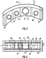
- Figure 2 is a schematic representation of the upper or lower planar face of the tibial cutting guide according to the invention, of which Figure 3 is a cross section.
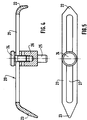
- Figure 4 is a schematic representation of the probe of the ancillary device according to the invention, of which Figure 5 is a top view.
- FIG. 1 shows the ancillary device according to the invention in place on a tibia (1).
- the fibula (2) has also been shown.
- This ancillary fundamentally comprises an intramedullary rod (3), inserted into the medullary canal of the tibia. It also includes an external aiming rod (4), parallel to the intramedullary rod (3), and held outside the tibia by means of two supports, respectively (5,6).
- the support (6) is pierced with a light, allowing precise adjustment of the external aiming rod relative to the tibia.
- the length of this rod (4) can be adjusted by means of a dial bearing the reference (8).
- This external aiming rod is intended to receive a tibial cutting guide (7), more particularly shown in FIGS. 2 and 3.
- This tibial cutting guide (7) is a metallic element of arcuate shape, comprising two main faces (18 , 19) planes and two curved faces respectively (11) and (12).
- the flat faces (18) and (19) are pierced with through holes (9,10) of different diameters.
- the orifice (9) is intended to receive the external aiming rod (4).
- the orifices (10) located on either side of this orifice (9) are intended to receive the feeler (20) of the tibial cutting guide, described in more detail later.
- the cutting guide is asymmetrical, one side extending more than the other.
- the most elongated side (13) corresponds to the internal side, that is to say which comes to be placed towards the inside of the joint when it is facing it.
- the other side is the outer side (14) of the joint.
- the curved faces (11) and (12) are also pierced with through orifices bearing the reference (15), gathered in five sets of two orifices, each of the games being oriented straight and parallel to the flat faces (18,19).
- said curved side faces (11) and (12) have two equally through slots (16) and (17), parallel to the planar faces (18,19), intended, as will be described in more detail later, to allow passing and guiding a saw to cut the tibia.
- FIGS. 4 and 5 show a representation of the feeler (20) of the tibial cutting guide.
- This probe essentially consists of a rectilinear metal blade (21), pierced with a light (27) aligned with the main dimension of said probe, in which a support (26) associated with a screw (24), a pin (25) being associated with said support (26).
- the pin (25) is intended to be inserted into the holes (10) of the tibial cutting guide described above.
- the support (26) associated with the screw (24) is intended to move the pin (25) relative to the probe (20).
- the two ends of the metal blade (21) are bent, respectively (22) and (23), the end (23) being of larger dimensions than the end (22).
- These ends (22) and (23) constitute the probing points proper, the end (22) corresponding to the healthy side of the tibial plateau, and the end (23) corresponding to the collapsed side also called pathological side of the tibial plateau.
- the height of the tibial cutting guide (7) is adjusted by positioning the feeler (20) in the different orifices (10) according to the healthy, then pathological side of the tibial plateau, the relative position of the probing points proper (22 , 23) can be adapted by moving the support (26) of the pin (25) in the hole (27), in order to be able to calibrate the cutting guide (7).
- the probe (20) is used successively in the external part and in the internal part, where one of the two orifices (10) is chosen according to the size of the patient's knee. This double probing makes it possible to define the quantity of bone to be cut in thickness.
- the tibial cutting guide (7) is fixed in the tibia by inserting pins in the holes (15) located on the side walls (11) and (12) of said cutting guide.
- the external aiming rod is then removed by sliding it through the orifice (9), as well as the intramedullary rod (3), and the tibial plateau is cut out in the upper slot (16) of said cutting guide in the tibia, the said pins playing in addition to the role of fixing the tibial cutting guide (7) in the tibia (1), the role of safety, guiding the saw blade horizontally.
- the tibial tray prosthesis can then be put in place, after having formed its location by means of forming pins, and judged its size by means of trial trays.
- the cutting guide is symmetrical with respect to the median plane. In this way, it is reversible and can be advantageously used for the right joint as for the left knee joint, it suffices to do so, to turn it over.
- this ancillary proves to be particularly suitable for the placement of prosthesis for tibial plateau, which ancillaries known to date did not allow get.
Landscapes
- Health & Medical Sciences (AREA)
- Surgery (AREA)
- Life Sciences & Earth Sciences (AREA)
- Biomedical Technology (AREA)
- Medical Informatics (AREA)
- Oral & Maxillofacial Surgery (AREA)
- Nuclear Medicine, Radiotherapy & Molecular Imaging (AREA)
- Transplantation (AREA)
- Physical Education & Sports Medicine (AREA)
- Engineering & Computer Science (AREA)
- Orthopedic Medicine & Surgery (AREA)
- Heart & Thoracic Surgery (AREA)
- Dentistry (AREA)
- Molecular Biology (AREA)
- Animal Behavior & Ethology (AREA)
- General Health & Medical Sciences (AREA)
- Public Health (AREA)
- Veterinary Medicine (AREA)
- Prostheses (AREA)
- Surgical Instruments (AREA)
Applications Claiming Priority (2)
| Application Number | Priority Date | Filing Date | Title |
|---|---|---|---|
| FR9112284 | 1991-10-01 | ||
| FR9112284A FR2681779B1 (fr) | 1991-10-01 | 1991-10-01 | Ancillaire pour la mise en place d'une prothese de plateau tibial. |
Publications (2)
| Publication Number | Publication Date |
|---|---|
| EP0538152A1 true EP0538152A1 (de) | 1993-04-21 |
| EP0538152B1 EP0538152B1 (de) | 1995-08-02 |
Family
ID=9417634
Family Applications (1)
| Application Number | Title | Priority Date | Filing Date |
|---|---|---|---|
| EP19920420337 Expired - Lifetime EP0538152B1 (de) | 1991-10-01 | 1992-09-29 | Hilfsinstrument zum Einsetzen einer Tibiaplateau-Prothese |
Country Status (4)
| Country | Link |
|---|---|
| EP (1) | EP0538152B1 (de) |
| DE (1) | DE69203821T2 (de) |
| ES (1) | ES2078012T3 (de) |
| FR (1) | FR2681779B1 (de) |
Cited By (11)
| Publication number | Priority date | Publication date | Assignee | Title |
|---|---|---|---|---|
| FR2720629A1 (fr) * | 1994-06-03 | 1995-12-08 | Landanger Landos | Ancillaire tibial pour la pose d'une platine de coupe sur l'extrémité d'un tibia à sectionner en vue de la mise en place d'une prothèse de genou. |
| EP0709062A1 (de) | 1994-10-27 | 1996-05-01 | Merck Biomaterial France | Tibiaresektionsinstrument |
| FR2726458A1 (fr) * | 1994-11-09 | 1996-05-10 | Perol Henri | Dispositif de visee et guide de coupe en vue de la mise en place d'une prothese totale unicompartimentale ou bicompartimentale du genou |
| US7237556B2 (en) | 2002-02-11 | 2007-07-03 | Smith & Nephew, Inc. | Image-guided fracture reduction |
| US7477926B2 (en) | 2004-03-31 | 2009-01-13 | Smith & Nephew, Inc. | Methods and apparatuses for providing a reference array input device |
| US7547307B2 (en) | 2001-02-27 | 2009-06-16 | Smith & Nephew, Inc. | Computer assisted knee arthroplasty instrumentation, systems, and processes |
| US7764985B2 (en) | 2003-10-20 | 2010-07-27 | Smith & Nephew, Inc. | Surgical navigation system component fault interfaces and related processes |
| US7794467B2 (en) | 2003-11-14 | 2010-09-14 | Smith & Nephew, Inc. | Adjustable surgical cutting systems |
| US7862570B2 (en) | 2003-10-03 | 2011-01-04 | Smith & Nephew, Inc. | Surgical positioners |
| US8109942B2 (en) | 2004-04-21 | 2012-02-07 | Smith & Nephew, Inc. | Computer-aided methods, systems, and apparatuses for shoulder arthroplasty |
| US8177788B2 (en) | 2005-02-22 | 2012-05-15 | Smith & Nephew, Inc. | In-line milling system |
Families Citing this family (13)
| Publication number | Priority date | Publication date | Assignee | Title |
|---|---|---|---|---|
| FR2710255A1 (fr) * | 1993-09-20 | 1995-03-31 | Smith & Nephew Richards France | Dispositif de détermination d'un plan de coupe de l'extrémité proximale d'un tibia. |
| WO1996029940A1 (fr) * | 1993-09-20 | 1996-10-03 | Smith & Nephew Richards France | Dispositif de determination d'un plan de coupe de l'extremite proximale d'un tibia |
| FR2714811B1 (fr) * | 1994-01-11 | 1998-04-24 | Lepine Groupe | Instrument ancillaire permettant la résection de l'extrémité supérieure d'un tibia. |
| FR2722392A1 (fr) * | 1994-07-12 | 1996-01-19 | Biomicron | Appareil de resection des condyles de genou pour la mise en place d'une prothese et procede de mise en place d'un tel appareil |
| US8603095B2 (en) | 1994-09-02 | 2013-12-10 | Puget Bio Ventures LLC | Apparatuses for femoral and tibial resection |
| FR2770765B1 (fr) | 1997-11-10 | 2000-01-07 | Osbone Sc | Guide de coupe tibiale |
| US20040153066A1 (en) | 2003-02-03 | 2004-08-05 | Coon Thomas M. | Apparatus for knee surgery and method of use |
| US8114086B2 (en) | 2004-03-08 | 2012-02-14 | Zimmer Technology, Inc. | Navigated cut guide locator |
| US7993341B2 (en) | 2004-03-08 | 2011-08-09 | Zimmer Technology, Inc. | Navigated orthopaedic guide and method |
| US7520880B2 (en) | 2006-01-09 | 2009-04-21 | Zimmer Technology, Inc. | Adjustable surgical support base with integral hinge |
| US7744600B2 (en) | 2006-01-10 | 2010-06-29 | Zimmer Technology, Inc. | Bone resection guide and method |
| FR3093418B1 (fr) * | 2019-03-04 | 2021-02-12 | Fh Orthopedics | Guide de coupe tibial pour réséquer un tibia d’un patient pour la pose d’une prothèse de genou |
| CN111870310A (zh) * | 2020-08-04 | 2020-11-03 | 北京力达康科技有限公司 | 一种胫骨截骨髓外、髓内多功能定位系统 |
Citations (3)
| Publication number | Priority date | Publication date | Assignee | Title |
|---|---|---|---|---|
| EP0327249A2 (de) * | 1988-02-03 | 1989-08-09 | Pfizer Hospital Products Group, Inc. | Apparat für Kniegelenksprothese |
| EP0337901A1 (de) * | 1988-04-01 | 1989-10-18 | Christian Broc | Einbaugerät insbesondere für das tibiale und/oder femorale Teil einer zweiteiligen Kniegelenkprothese |
| US4952213A (en) * | 1989-02-03 | 1990-08-28 | Boehringer Mannheim Corporation | Tibial cutting guide |
-
1991
- 1991-10-01 FR FR9112284A patent/FR2681779B1/fr not_active Expired - Fee Related
-
1992
- 1992-09-29 DE DE1992603821 patent/DE69203821T2/de not_active Expired - Fee Related
- 1992-09-29 EP EP19920420337 patent/EP0538152B1/de not_active Expired - Lifetime
- 1992-09-29 ES ES92420337T patent/ES2078012T3/es not_active Expired - Lifetime
Patent Citations (3)
| Publication number | Priority date | Publication date | Assignee | Title |
|---|---|---|---|---|
| EP0327249A2 (de) * | 1988-02-03 | 1989-08-09 | Pfizer Hospital Products Group, Inc. | Apparat für Kniegelenksprothese |
| EP0337901A1 (de) * | 1988-04-01 | 1989-10-18 | Christian Broc | Einbaugerät insbesondere für das tibiale und/oder femorale Teil einer zweiteiligen Kniegelenkprothese |
| US4952213A (en) * | 1989-02-03 | 1990-08-28 | Boehringer Mannheim Corporation | Tibial cutting guide |
Cited By (12)
| Publication number | Priority date | Publication date | Assignee | Title |
|---|---|---|---|---|
| FR2720629A1 (fr) * | 1994-06-03 | 1995-12-08 | Landanger Landos | Ancillaire tibial pour la pose d'une platine de coupe sur l'extrémité d'un tibia à sectionner en vue de la mise en place d'une prothèse de genou. |
| EP0709062A1 (de) | 1994-10-27 | 1996-05-01 | Merck Biomaterial France | Tibiaresektionsinstrument |
| FR2726177A1 (fr) * | 1994-10-27 | 1996-05-03 | Impact | Instrumentation ancillaire tibiale |
| FR2726458A1 (fr) * | 1994-11-09 | 1996-05-10 | Perol Henri | Dispositif de visee et guide de coupe en vue de la mise en place d'une prothese totale unicompartimentale ou bicompartimentale du genou |
| US7547307B2 (en) | 2001-02-27 | 2009-06-16 | Smith & Nephew, Inc. | Computer assisted knee arthroplasty instrumentation, systems, and processes |
| US7237556B2 (en) | 2002-02-11 | 2007-07-03 | Smith & Nephew, Inc. | Image-guided fracture reduction |
| US7862570B2 (en) | 2003-10-03 | 2011-01-04 | Smith & Nephew, Inc. | Surgical positioners |
| US7764985B2 (en) | 2003-10-20 | 2010-07-27 | Smith & Nephew, Inc. | Surgical navigation system component fault interfaces and related processes |
| US7794467B2 (en) | 2003-11-14 | 2010-09-14 | Smith & Nephew, Inc. | Adjustable surgical cutting systems |
| US7477926B2 (en) | 2004-03-31 | 2009-01-13 | Smith & Nephew, Inc. | Methods and apparatuses for providing a reference array input device |
| US8109942B2 (en) | 2004-04-21 | 2012-02-07 | Smith & Nephew, Inc. | Computer-aided methods, systems, and apparatuses for shoulder arthroplasty |
| US8177788B2 (en) | 2005-02-22 | 2012-05-15 | Smith & Nephew, Inc. | In-line milling system |
Also Published As
| Publication number | Publication date |
|---|---|
| FR2681779A1 (fr) | 1993-04-02 |
| FR2681779B1 (fr) | 1993-12-03 |
| ES2078012T3 (es) | 1995-12-01 |
| EP0538152B1 (de) | 1995-08-02 |
| DE69203821T2 (de) | 1995-11-23 |
| DE69203821D1 (de) | 1995-09-07 |
Similar Documents
| Publication | Publication Date | Title |
|---|---|---|
| EP0538152B1 (de) | Hilfsinstrument zum Einsetzen einer Tibiaplateau-Prothese | |
| EP0538153B1 (de) | Modulare Hilfseinrichtung zum Einsetzen einer Knieprothese | |
| EP0721314B1 (de) | Vorrichtung zur resektion von kondylen eines knies zum einzetzen einer knieprothese | |
| EP1275345B1 (de) | Hilfsvorrichtung zur Positionierung eines Elle- und/oder Speicheteils einer Ellenbogenprothese | |
| FR2649604A1 (fr) | Instrument ancillaire chirurgical de reperage de l'entree et de la direction du tunnel d'insertion femorale d'un neo-ligament dans des conditions d'isometrie totale | |
| FR3030221B1 (fr) | Instrument et procede de guidage d’une broche de guidage | |
| EP0685210B1 (de) | Femorales kondiläres und patellares Implantat, und chirurgisches Instrument für die Implantierung | |
| FR2943528A1 (fr) | Instrumentation chirurgicale de resection de l'extremite d'un os long | |
| EP0337901A1 (de) | Einbaugerät insbesondere für das tibiale und/oder femorale Teil einer zweiteiligen Kniegelenkprothese | |
| EP1643916A2 (de) | Vorrichtung zur unterstützung bei der implantation einer knietotalprothese | |
| FR2726755A1 (fr) | Dispositif de blocage temporaire de deux parties d'une piece osseuse | |
| FR2556583A1 (fr) | Plaques d'osteosynthese pour derotation osseuse, en particulier derotation femorale | |
| FR2885293A1 (fr) | Instrument de viseee de l'axe mecanique du femur | |
| FR2911264A1 (fr) | Viseur pour chirurgie ligamentaire du genou | |
| FR2721202A1 (fr) | Prothèse fémoro-patellaire et dispositif ancillaire pour former une empreinte trochléenne de réception de cette prothèse. | |
| FR2737848A1 (fr) | Instrumentation de mise en place d'un implant rotulien prothetique | |
| FR2752519A1 (fr) | Guides de coupe tibiale et femorale pour installation d'une prothese totale de genou | |
| WO1987002883A1 (fr) | Appareillage pour la pose d'une endo prothese du genou | |
| FR2935092A1 (fr) | Ensemble d'ancillaires pour implanter une prothese de genou. | |
| FR2728782A1 (fr) | Prothese de genou | |
| FR2703584A1 (fr) | Viseur de coupes tibiales. | |
| FR2806901A1 (fr) | Materiel de coupe femorale pour la mise en place d'une prothese totale du genou | |
| FR2648699A1 (fr) | Viseur polyvalent pour prothese totale du genou a glissement | |
| FR2726458A1 (fr) | Dispositif de visee et guide de coupe en vue de la mise en place d'une prothese totale unicompartimentale ou bicompartimentale du genou | |
| FR3071147A1 (fr) | Dispositif d'aide a la pose d'une prothese de genou, outil distracteur et equilibreur du systeme ligamentaire du genou |
Legal Events
| Date | Code | Title | Description |
|---|---|---|---|
| PUAI | Public reference made under article 153(3) epc to a published international application that has entered the european phase |
Free format text: ORIGINAL CODE: 0009012 |
|
| 17P | Request for examination filed |
Effective date: 19930129 |
|
| AK | Designated contracting states |
Kind code of ref document: A1 Designated state(s): BE CH DE ES GB IT LI |
|
| 17Q | First examination report despatched |
Effective date: 19941223 |
|
| GRAA | (expected) grant |
Free format text: ORIGINAL CODE: 0009210 |
|
| AK | Designated contracting states |
Kind code of ref document: B1 Designated state(s): BE CH DE ES GB IT LI |
|
| ITF | It: translation for a ep patent filed | ||
| REF | Corresponds to: |
Ref document number: 69203821 Country of ref document: DE Date of ref document: 19950907 |
|
| GBT | Gb: translation of ep patent filed (gb section 77(6)(a)/1977) |
Effective date: 19950904 |
|
| REG | Reference to a national code |
Ref country code: ES Ref legal event code: FG2A Ref document number: 2078012 Country of ref document: ES Kind code of ref document: T3 |
|
| PLBE | No opposition filed within time limit |
Free format text: ORIGINAL CODE: 0009261 |
|
| 26N | No opposition filed | ||
| PGFP | Annual fee paid to national office [announced via postgrant information from national office to epo] |
Ref country code: ES Payment date: 19980916 Year of fee payment: 7 |
|
| PGFP | Annual fee paid to national office [announced via postgrant information from national office to epo] |
Ref country code: DE Payment date: 19980917 Year of fee payment: 7 |
|
| PGFP | Annual fee paid to national office [announced via postgrant information from national office to epo] |
Ref country code: GB Payment date: 19980922 Year of fee payment: 7 Ref country code: CH Payment date: 19980922 Year of fee payment: 7 |
|
| PGFP | Annual fee paid to national office [announced via postgrant information from national office to epo] |
Ref country code: BE Payment date: 19981016 Year of fee payment: 7 |
|
| PG25 | Lapsed in a contracting state [announced via postgrant information from national office to epo] |
Ref country code: GB Free format text: LAPSE BECAUSE OF NON-PAYMENT OF DUE FEES Effective date: 19990929 |
|
| PG25 | Lapsed in a contracting state [announced via postgrant information from national office to epo] |
Ref country code: LI Free format text: LAPSE BECAUSE OF NON-PAYMENT OF DUE FEES Effective date: 19990930 Ref country code: ES Free format text: LAPSE BECAUSE OF NON-PAYMENT OF DUE FEES Effective date: 19990930 Ref country code: CH Free format text: LAPSE BECAUSE OF NON-PAYMENT OF DUE FEES Effective date: 19990930 Ref country code: BE Free format text: LAPSE BECAUSE OF NON-PAYMENT OF DUE FEES Effective date: 19990930 |
|
| BERE | Be: lapsed |
Owner name: MAJOU CLAUDE Effective date: 19990930 Owner name: COLLOMB JEAN Effective date: 19990930 Owner name: IMPACT Effective date: 19990930 |
|
| REG | Reference to a national code |
Ref country code: CH Ref legal event code: PL |
|
| GBPC | Gb: european patent ceased through non-payment of renewal fee |
Effective date: 19990929 |
|
| PG25 | Lapsed in a contracting state [announced via postgrant information from national office to epo] |
Ref country code: DE Free format text: LAPSE BECAUSE OF NON-PAYMENT OF DUE FEES Effective date: 20000701 |
|
| REG | Reference to a national code |
Ref country code: ES Ref legal event code: FD2A Effective date: 20001013 |
|
| PG25 | Lapsed in a contracting state [announced via postgrant information from national office to epo] |
Ref country code: IT Free format text: LAPSE BECAUSE OF NON-PAYMENT OF DUE FEES;WARNING: LAPSES OF ITALIAN PATENTS WITH EFFECTIVE DATE BEFORE 2007 MAY HAVE OCCURRED AT ANY TIME BEFORE 2007. THE CORRECT EFFECTIVE DATE MAY BE DIFFERENT FROM THE ONE RECORDED. Effective date: 20050929 |