EP0538196B1 - Dispositif pour le raccordement d'un tuyau flexible sous le crépi d'un mur et d'une robinetterie sur le crépi d'un mur - Google Patents
Dispositif pour le raccordement d'un tuyau flexible sous le crépi d'un mur et d'une robinetterie sur le crépi d'un mur Download PDFInfo
- Publication number
- EP0538196B1 EP0538196B1 EP92810773A EP92810773A EP0538196B1 EP 0538196 B1 EP0538196 B1 EP 0538196B1 EP 92810773 A EP92810773 A EP 92810773A EP 92810773 A EP92810773 A EP 92810773A EP 0538196 B1 EP0538196 B1 EP 0538196B1
- Authority
- EP
- European Patent Office
- Prior art keywords
- casing
- neck
- head
- conduit
- piece
- Prior art date
- Legal status (The legal status is an assumption and is not a legal conclusion. Google has not performed a legal analysis and makes no representation as to the accuracy of the status listed.)
- Expired - Lifetime
Links
Images




Classifications
-
- E—FIXED CONSTRUCTIONS
- E03—WATER SUPPLY; SEWERAGE
- E03C—DOMESTIC PLUMBING INSTALLATIONS FOR FRESH WATER OR WASTE WATER; SINKS
- E03C1/00—Domestic plumbing installations for fresh water or waste water; Sinks
- E03C1/02—Plumbing installations for fresh water
- E03C1/021—Devices for positioning or connecting of water supply lines
Definitions
- the invention relates to a device as a connection between at least one flexible plaster piping and a fitting to be plastered, comprising one in a can head and at least one attachable to this Can neck that can be dismantled and an angled tube piece that can be inserted into and fixed in the can, the can with a view to easy assembly of the angle tube piece the at least one pipe can be opened to the front in such a way that it comes out of the can removed and connected to the end of the at least one pipe angled pipe section can be inserted into the can from the front.
- a device of the type mentioned is such. B. from CH-663 814-A5 known. It is a connection device for outlet fittings, as they are typically is used in bathroom installations. she includes one laid in a box under the wall surface and connection piece connected to a flexible line, which is angled and a connection option for the mixer to be arranged over plaster.
- the Box in which the angle piece can be fixed can be from be closed at the front with a lid.
- connection device is in that the pipeline (inner pipe) to connect to the angled tube piece is not pulled out of the protective tube, but only bent out and when inserting the same the connected pipeline is not laborious again the protective tube must be pushed back, but simply can be bent back.
- US 5,031,940 discloses a can with an angle tube piece.
- the can has a removable neck.
- the can head is in one Rear wall part and a front wall part can be dismantled. With a lock ring the angle tube piece can be fixed in the box.
- a housing that can be opened from the front is also made of CH-650 823-A5 known.
- the one on the conduit assembled pipe bend inserted into the housing from the front and be covered with the clip-on cover.
- connection technology in which how mentions the pipeline for the purpose of assembling the connector is bent out of the wall and then into the junction box covered and assembled there, there is another contrasting technology, in which the angle tube piece in the can first on the wall resp. in a recess attached to the wall and then the correctly cut one Pipeline is connected.
- An example of a device which is based on this long-known principle, can be found in German utility model GM 79 27 117.
- the elbow pipe piece is attached to a carrier fixed on the wall. After connecting the pipeline the elbow pipe piece and the connection connection each with a clampable protective sleeve made of plastic.
- connection devices where the elbow pipe piece is attached to the wall in a rubber sleeve, so that afterwards the correctly cut pipe is connected can be.
- European patent application EP 0 354 177-A1 Again, the facility is initially in a wall recess fixed and then the flexible, cut pipe connected.
- a two-part plastic protective sleeve to cover the angle tube piece resp. the terminal clamp intended.
- the advantage of the second assembly technique mentioned is there in that first the elbow pipe piece on the right one Can be assembled in place and only the pipe afterwards is to be connected. So the elbow pipe piece needs during during assembly not to be held in the hand. This makes it easier also the attachment of the clamping ring device.
- requirement for this convenient type of installation is that the wall recess is large enough to be comfortable with can be accessed with a wrench. This is but not always the case, but rather depends on the the respective structural conditions. It is problematic even if the can is not so good in the wall recess can be attached so that they occur during assembly Forces (e.g. torques when attaching the clamping ring connection) can record.
- the object of the invention is therefore to provide a device to specify the type mentioned at the outset, which at the status of Technology avoids existing disadvantages. In particular, should easy to set up under the most varied of conditions and be easy to assemble.
- the solution to this problem is that in order to create a additional, alternative mounting option, a division of the can into the can head and the at least one can neck is selected such that the one inserted into the can head and angled pipe section fastened therein with its on the at least one pipe end to be connected protrudes from the can head in such a way that the correctly cut one at least one pipe can be connected to this end without that the angle tube piece has to be removed from the can head, and that the subsequently attached to the can head at least one can neck both that connected end of the angled pipe section as well as a section of the connected encloses at least one pipeline.
- the device according to the invention not only brings assembly Advantages with it, but also in terms of production. While previously inserting the usually metallic Elbow pipe piece in the plastic box for those components was tedious, based on the principle that that Angled tube piece fixed in the socket before connection was, it is now because of the short and after Can open at the front without any problems, also relatively large angle pipe pieces already in the factory in the associated Fix cans. The dimensions of these cans need no longer with a view to inserting the angle tube piece to be oversized.
- connection device From the point of view of the fitter, it is of course particularly pleasant that he can decide on the spot in which way he want to install the connection device.
- the pipe has a clamping ring device with a Union nut provided.
- the can is so in Can head and can neck separated that the angled tube piece with the union nut protruding from the can head. This way there is enough space to handle one Wrench when connecting the pipeline the angle tube piece inserted in the can head ensures.
- the can neck is advantageously designed such that an outer tube (Protective tube) of the pipeline can. This can prevent that in the Usually pulls the ribbed outer tube out of the can neck and as a result, the inner tube, respectively. the junction is no longer covered. With a cross-ribbed pipe this z. B. with an appropriately sized rib accomplish on the inside of the can neck. For any equipped outer tubes can be the intended Reach the goal with a clamp or the like.
- the can neck shows lower, the can end facing away from a plier-like (or C-shaped) clamping element for clamping the outer tube on.
- the clamping element can be used with the help of tools or be operable by hand. It is particularly advantageous one that is designed in the manner of a ring open on one side is, which is radially resilient due to its shape. in the At rest, the inner diameter of the ring is slightly smaller than the outside diameter of the pipe to be fixed. The latter can therefore be clamped radially.
- a ribbed outer tube are suitable on the inside Clamping element formed on transverse ribs.
- the clamping member is preferably as a substantially remote Element trained.
- a connecting bridge, the one hinge-like mobility of the clamping member relative to the Can neck enables, connects the clamping member with the can neck.
- Can neck, connecting web and clamping member are preferred from the same mould.
- the device according to the invention is as versatile as possible can be used, it is recommended to use the can neck train bendable.
- the can can then be used for both 90 ° and also for acute-angled, e.g. B. 70 ° arrangements can be used.
- Narrow-angle facilities are typically used at Lightweight wall applications used.
- a bellows-type can be used on the can neck to achieve flexibility Section be formed. But it is also possible the can neck from an elastic or u. U. plastically deformable To manufacture material. Preferably the can neck only bendable in the bellows section and otherwise stiff.
- the can neck encloses the outer tube in a drip-proof manner, then water damage can occur with minor leaks be avoided.
- the can neck can so after connecting the pipe to the elbow pipe attached and does not need on the outer tube to be displaceable (such as in the prior art according to EP 0 354 177-A1). He can also do it later can be attached at any time and does not necessarily have to be before Connecting the piping slipped over the outer pipe will.
- a can neck that can both be pushed over the outer tube as this can also clamp is characterized from that the plug-and-socket fastener latches at least two Have positions, the cross-section in the first position of the can neck is large enough to fit the can neck to be able to slide over the outer tube, and in the second Position is small enough to clamp the outer tube.
- the connecting means between the can neck and the can head are designed so that the can neck can also be attached to the can head if the connector means locked in the first position are.
- the can can then z. B. on delivery from the factory handled as a one-piece, coherent housing will.
- the can neck can be from Can head removed, put over the outer tube and after connecting the inner tube to the angle tube piece at the desired location by radial pressure on the outer tube be fixed.
- the mentioned can neck according to the invention can also be independent be used by the other features of the invention.
- a can neck that can be assembled from two half-shells or a can neck with a double locking plug connection generally used for all those cans that are in a can head and a can neck are separable.
- the can head is e.g. B. cylindrical respectively. in terms of form derived from a cylinder, the cylinder axis essentially perpendicular to the axis of the (installed under plaster) Pipeline stands.
- the fitting to be connected via plaster facing side of the can head is with a lid resp.
- Locking ring partially lockable.
- the can head At the point where the angled pipe piece from the can head (e.g. downwards) should protrude, is the can head with a recess provided that is open towards the front, so that Angled tube piece can be inserted into the can head from the front.
- the locking ring encompasses the angle tube piece on his facing the fitting to be mounted on plaster The End.
- the can head shows its interior consists of at least one groove-like depression, in the form of a rib-like projection of the angled tube piece intervenes. If the elbow pipe piece with the locking ring is fixed in the can, then the rib-like lies Projection in the groove-like depression.
- the elements mentioned interlock in a dovetail shape a.
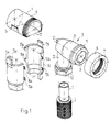
- FIG. 1 shows the individual parts of the device according to the invention in perspective.
- One under plaster installed pipeline with a flexible inner tube 1 and preferably ribbed and also flexible outer tube 2 is to be connected to an angled pipe section 3 in such a way that a tap to be arranged over plaster (e.g. a water tap or a mixing head) can be connected.
- a tap to be arranged over plaster e.g. a water tap or a mixing head
- the tube extension 22 has a clamping ring closure with a union nut 10.
- the cap nut 10 includes the tube extension 22 from the outside. For the rest is the clamping ring closure is designed in a manner known per se.
- the union nut 10 can be removed from the tube extension 22 or be captively connected to it.
- the tube extension 21 is with a z. B. annular stop flanges 11 provided that the opening 9 slightly is set back. It enables the angle tube piece 3 to fix in the can.
- the tube extension 21 has an internal thread 7 provided for connecting the surface-mounted fitting.
- the box which holds the connector (3) just described protects, preferably consists of several individual parts together.
- it is a cylindrical can head 4, one essentially two half-shells 5a, 5b which can be assembled and one Lock ring 6.
- the can head 4 is according to a preferred embodiment trained so that he the whole angle tube piece 3 with the exception the union nut 10 takes.
- it is cylindrical, more or more less adapted to the pipe socket 21.
- the elbow pipe piece 3 is housed in the can head 4, the axes run of the cylindrical can head 4 and the tube extension 21 parallel to each other.
- the cylindrical can head 4 has in the jacket a recess 23 for the tube extension 22. she runs from the front in the axial direction to the rear, so that the angled tube piece 3 with its tube extension 22 from the front in the can head 4 can be inserted.
- the recess 23 must therefore at least as wide as the diameter of the tube extension 22 be.
- the can head 4 thus looks arcuate out. Preferably, its angle extends more than 180 °.
- the can head 4 is closed on the rear side. On its outside it has z. B. suitable protrusions (one of which can be seen as 14) on to to attach the can neck.
- the cover is screwed on like a union nut.
- the locking ring 6 thus comprises the can head 4 and gives it greater stability.
- the can neck is tubular and exposes itself the two half shells 5a and 5b together.
- the tubular The can neck is divided into two, as it were, in the longitudinal direction of the axis.
- the Half shells 5a and 5b can be plugged together.
- the inside diameter of the tubular can neck is so large that he can take the union nut 10. At the bottom it narrows so far that the outer tube during assembly 2 is pinched. The mentioned narrowing does not need mandatory to be visible from the outside. A purely inside In principle it is enough.
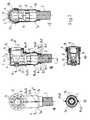
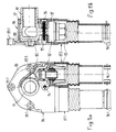
- Fig. 2a-e shows the box in the assembled state.
- Fig. 2a shows a front view of the inventive device.
- the pipeline outer pipe 2
- the can neck half shells 5a, 5b
- the can head in Fig. 2a hidden
- the Locking ring 6 recesses 19 so that it with a suitable tool (e.g. plastic pipe with appropriate Studs at the end) can be screwed tight.
- the wells are preferably distributed regularly along the circumference.
- the opening 9 of the angle tube piece housed in the can 3 is e.g. B. equipped with a thread in which the flush-mounted fitting can be screwed in.
- a different type of pressure density can also be used Connection for connecting the valve may be provided.
- Fig. 2d shows a section A-A through the can neck.
- the water-bearing inner tube 1 This is from one Surround outer tube 2, which on the one hand, the inner tube 1st protects and on the other hand noise insulation (flow noises) brings with it.
- the whole thing is enclosed by the can neck with its two half shells 5a, 5b, which by suitable Connection means (push buttons 15a, 15b and 18a, 18b) be held together.
- Fig. 2b shows the device in a longitudinal section perpendicular to the wall surface.
- the outer tube 2 is from the can neck held with its narrowed end.
- the outer tube has 2 cross ribs 24.1, 24.2, 24.3 and cross grooves 25.1, 25.2, 25.3.
- suitable circumferential ribs 26.1, 26.2 engage in the transverse grooves 25.1 and 25.2.
- the can neck in the Assembled state therefore not via the outer tube is movable.
- the angle tube piece 3 is fixed in the can head 4.
- bracket 20 fits. So the rib 12 remains in the holder 20, these two elements preferably designed in a dovetail-shaped manner.
- the stop flanges 11 at the front end of the tube extension 21 fits positively into the can head 4.
- the pipe socket 21 is centered by it.
- the stop flange 11 is like this arranged near the front end of the pipe socket 21 that by screwing on the locking ring 6, which in turn the tubular extension 21 at its front end form-fitting includes an axial force on the tube extension 21st can be exercised in the direction of the bracket 20.
- the angle tube piece is both through the bracket 20 and the locking ring 6 held in the can head.
- FIG. 2c shows a section through the device according to the invention parallel to the wall surface (section C-C). It is clearly recognizable that the cylindrical can head 4 encloses the tubular extension 21 in an arc. The cross section The arch formed closes an angle of more than 180 °. Because of the positively fitted stop flanges 11 is the tube extension 21 without help the locking ring 6 centered in the can head. The stronger the can head 4 comprises the tube extension 21 in terms of angle, the more stable this part of the can is.
- the recess 23 in the jacket of the can head 4 must of course in any case at least as large as the diameter of the tube extension 22 be so that the angle tube piece 3 can be inserted from the front is.
- the Pipe extension 22 represents a narrowing in a certain sense: Both the union nut 10 and the pipe socket 21 with its stop flanges 11 have a larger one Diameter than the pipe neck 22. If the recess 23 in Jacket head 4 is designed sufficiently tight, then So can the elbow pipe 3 with attached can neck (even if the locking ring 6 has been removed) not be pulled out of the can. Rather, it is only at removed can neck inserted from the front.
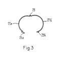
- Fig. 3 shows an axial section through a particularly preferred Embodiment of the can neck.
- the hinge 28 is preferably thin Plastic skin formed, which can be easily bent. There the can neck does not have to be opened often, one is enough simple and cheap hinge construction.
- the can head 4 is now in the milled slot attached to the wall in a suitable place. So the situation the fitting to be installed over plaster.
- the can neck (Half-shells 5a, 5b) and the locking ring 6 was previously approved. Likewise is the angle tube piece 3 has been removed.
- inner tube 1 and outer tube 2 are set to the desired one Cut back length.
- the flexible pipe is for this purpose perpendicular to the wall surface from the Slot bent out. So you don't work in a tight spot of the wall slot.
- the locking ring 6 is screwed onto the can head 4. Since the stop flanges 11 are preferably small little protrudes beyond the front end of the can head 4, becomes the angle tube piece when screwing the locking ring 6 3 pushed backwards. It is therefore between the can head 4 and locking ring 6 clamped. It glows a that because of this clamping effect, the rib 12 in the holder 20 is held (even if these two elements are not designed to lock) and thereby twisting of the angled tube piece around the axis of the tube extension 21 prevented becomes.
- the second type of installation described below is special then an advantage if the wall connections in one large wall recess are to be attached, which have a lot of space for Fiddles free.
- the can head 4 is first fixed in the appropriate place in the wall recess.
- the angle tube piece 3 is preferably located already in the can head 4.
- the can head 4 with the inserted angle tube piece 3 and the screwed lock ring So 6 can be treated as one part. This has the advantage that not a single one of them can be lost.
- the angle tube piece 3 e.g. B. in the event of a defect or a leaky connection with the inner tube or when replacing the inner tube itself can be.
- thick pipes e.g. 20 mm diameter and more
- the pipe should be on one if possible short length must be exposed. This is at the invention thereby ensures that the can neck can be dismantled is formed and not pushed back over the outer tube 2 must be accessible so that the union nut 10 becomes.
- the inner and outer tubes are flexible, d. H. are easily bendable.
- the outer tube can, for. B. quite be relatively rigid.
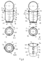
- the can neck 30 is from below pushed into the can head 31. That means with the lower opening of the can head 31 encloses the can neck 30, the outside diameter of which is somewhat smaller is measured.
- the angle tube piece 3 is, as shown in the Fig. 2 described, fixed in the can head 31. That is, the on the axial continuation of the tube extension 21 on the back of the angle tube piece 3 provided rib 12 is in a bracket 20, which on the inside of the can head 31st is molded, fixed. The angle tube piece 3 due to the stop flange provided on the tube extension 21 11 engaging locking ring 33 backwards into the holder 20 pressed.
- the locking ring 33 is screwed into the socket head 31.
- the can head 31 has a front face suitable thread.
- the can head has 31 a recess 23. Through this, the angle tube piece 3 can be removed to the front.
- a snap ring 32 is now provided, the front opening of the can head 31 from the outside includes.
- the snap ring 32 has a thread extension 34 on the one hand and on the other hand a housing cover filling the recess 23 on.
- the thread extension 34 covers the remaining part from about 60 °.
- the can head 31 covers preferably at least 180 ° of the internal thread. It is but also possible with a smaller angle component get along with the can head because the snap ring 32 always covers the remaining angular portion.
- 5a-c illustrates a preferred type of fixation an angle tube piece 44 in a can head according to the invention 35.
- the aim of this fixation is to ensure that the assembly forces acting as efficiently as possible on the anchorage of the Transfer can head. From the analysis of the occurring Forces and torques result in the intersection of the Axis of the horizontal tube extension 37 with that of vertical pipe neck 36 of the angled pipe piece 44 the occurring Forces are best intercepted and transferred can. It is therefore advantageous if as close as possible this center provides means for absorbing the forces are.
- flanges 38a, 38b after forward pipe extension 37 and as close as possible the axis of the vertical tube extension 36 two flanges 38a, 38b attached. These are in suitable abutments 41a, 41b, which are molded on the inside of the can head 35, in a form-fitting manner captured.
- a locking ring 39 is designed that in the screwed-in position the flanges 38a, 38b in the abutments 41a, 41b. This allows both in the axis of the tube extension 37 and in the axis of the tubular extension 36 acting torques will.
- Ears 43a, 43b are formed on the outside of the can head 35. she lie in the same plane as the flanges 38a, 38b.
- the ears 43a, 43b are provided with bores 42a, 42b, so that the can head z. B. on a holding iron or the wall itself can be screwed tight.
- Anchored in this way Angled tube piece 44 is also the one when tightening the Union nut 10 (for connecting the inner tube 1) survive the onset of force.
- the can head can be according to any of the foregoing Examples are executed. He can completely be trained differently, d. H. he doesn't necessarily need to be openable to the front.
- the can neck 45 consists essentially of two half-shells 46a, 46b. Its inside diameter is typical same size as that of the can head 4 on its lower The End.
- the can neck 45 is formed by means of two suitably designed Tabs 50a, 50b on a circumferential projection 49 the can head 4 attached.
- the projection 49 is on the outside molded at the lower end of the can head 4.
- the tabs 50a, 50b are hook-shaped and have a sufficient elasticity to be pushed over the projection 49 and cling to it to be able to.
- the can neck 45 narrows at its lower end (narrowing 47a, 47b).
- the crux of the present embodiment is now that the two half-shells 46a, 46b through suitable plug fasteners are put together in this way that at least in the area of the constrictions 47a, 47b form two different internal cross sections can.
- two snap locks 51a, 51b are provided, which assume two latching positions can.
- FIG. 6 is z. B. molded onto the half-shell 46b, slid over an M-shaped tab can be. If the nose in one of the two throats of the M-shaped tab engages, then exists between the two Half shells 46a, 46b a gap 53. If the can neck then pressed together by radial pressure, then the nose jumps into the second throat of the M-shaped tab, whereby the can neck 45 closes tightly.
- the inner cross section In the first latching position, the inner cross section is in the The area of the constrictions 47a, 47b at least so large that the fins 48.1, 48.2 over the finned outer tube 2 (cf. Fig. 2) are pushed more or less without hindrance can. But as soon as the snap locks 51a, 51b in the second position, the cross-section narrows in Area of constrictions 47a, 47b so strong that the ribs 48.1, 48.2 into the transverse grooves of the outer tube (see FIG. 2) intervention. The can neck can then with respect to the outer tube no longer be postponed.
- connection means (tabs 50a, 50b, projection 49) formed so that they keep the can head and can neck together can if the can neck has the larger cross section (cf. Fig. 6d, e).
- This can be done e.g. B. thereby achieve that the tabs 50a, 50b so strong over the projection 49 grasp that the intervention even in the larger Cross section is not lost.
- Fig. 6d this is done indicated a gap between can head 4 and can neck 45.
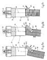
- Fig. 7a, b shows a can with a flexible neck and pliers-like Clamping member.
- a can head 54 and a can neck 55 are (e.g. according to one of the embodiments explained above) can be assembled into a can.
- a flange 56 is formed with one or more bores 57. The can head 54 can be attached to this flange 56 the desired place in a wall recess.
- a snap ring 58 serves to close the can head 54 in a manner explained with reference to FIGS. 4a-c.
- the can neck 55 has Embodiment of the invention a section with a bellows 59 on. This enables the lower, the can head 54 opposite end of the can neck 55 with respect to the longitudinal axis 66 to bend.
- the lower end of the can neck 55 can be So for example in a 60 ° position with respect to Front opening axis 67 (which is generally perpendicular to the Wall surface is aligned).
- FIG. 7b which the Section A-A according to FIG. 7a shows
- Er is, for example, with reinforcing ribs running around the outside 63.1, 63.2.
- Two tabs 65.1, 65.2. are on the inside of the ring e.g. B. two transverse ribs 64.1, 64.2 formed.
- the ring 62 is connected to the can neck 55 via a connecting piece 61.
- the annular clamping member with advantage a central angle that is of the order of magnitude of 270 °.
- the tabs 65.1, 65.2 protrude radially outward. Between the two tabs 65.1, 65.2 and annular part of the clamping member becomes an angle of 90 ° educated.
- the clamping member 60 can be under Bend apart overcoming an inherent spring force and slide over a ribbed protective tube. If the radial Pull apart the ring 62 provided tabs 65.1, 65.2 are released, then the ring 62 engages around it Protection tube like pliers, the ribs 64.1, 64.2 in corresponding Engage grooves in the protective tube. To this The protective tube is fixed in the direction of the longitudinal axis 66. It cannot slide out of the neck of the can.
- the connecting piece 61 is designed so that it is on the one hand can absorb the tensile forces that occur without breaking, and on the other hand the radial mobility of the ring ends not affected.
- the clamping member 60 hinge-like around the connecting piece 61 fold back.
- the connecting piece 61 suitably thin (if necessary with an additional constriction).
- the can parts including the clamping element molded from plastic.
- the can neck 55 is in present case tubular. He is special cannot be opened along a longitudinal axis. This means, that it must be passed over a protective tube 68. That is, under certain conditions, it must run along the ribbed protective tube 68 to be displaceable. According to the present Example is this movability by folding back of the clamping member 60 around the connecting piece 61 reached (Fig. 8a).
- the clamping member is on the side on the protection tube 68. With its tabs 65.1, 65.2 it slides over the ribs 70 Clamping organ at an oblique (e.g. 45 °) angle to the Is the longitudinal axis of the protective tube 68, the ribs 70th "Grid through” under tabs 65.1 and 65.2. this will additionally favored by the not particularly acute angle between the tabs 65.1, 65.2 and the circular arc Inner wall of the clamping member.
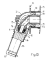
- FIG the invention Another preferred embodiment is intended to be shown in FIG the invention will be explained.
- These are a so-called lightweight wall box.
- a lightweight wall is used that it on the visible side is flush and protrudes from the rear.
- Fig. 10 it is a acute-angled arrangement, in which the axis of the domestic water supply pipe with the axis of the outflow Forms a 70 ° angle.
- a can neck 71 on a can head 72 z. B. by means of plug closure attachable.
- the division into can head 72 and Can neck 71 is selected such that a union nut 74 an angle tube piece 73 (which also has a 70 ° angle between inlet and outlet) from the can head 72 down resp. protrudes diagonally to the rear when the Can neck 71 is removed.
- the pipe neck pointing forward 75 (for connecting a fitting) has a length that is in corresponds approximately to the thickness of the lightweight wall.
- the pipe extension 76 pointing obliquely downwards already has this mentioned clamping ring closure for clamping a Plastic pipe.
- the angle tube piece 73 is in the can head 72 with screws 77.1, 77.2 screwed from the visible side of the lightweight wall.
- the screws 77.1, 77.2 sit between the pipe socket 75 and an approach 81 of the can head which surrounds this 72.
- tubular extension 81 sits slidably a sleeve 80. This protrudes from the front Mounting flange 79 radially outwards. Due to the movability the sleeve 80 on the neck 81 can Use a can for different wall thicknesses.
- the can head 72 has one Mounting flange 78 on. This can be on the Screw the back of the lightweight wall tight.
- the sleeve 80 is from the visible side of the lightweight wall onto shoulder 81 postponed. It also has holes for attaching it provided on the front of the lightweight wall.
- the lightweight wall is sandwiched between the rear, Fastening flange 78 formed on the can head 72 and the front, slidably mounted on the can head 72 Mounting flange 79 clamped. This leads to a good fixation of the can.
- the can neck 71 is already detailed above described inventive variant bendable. It has a first and a second rigid section 82 resp. 83, and an interposed flexible Section 84. At the bottom of the rigid section 83 is a clamping member 85, which is also has already been described above.
- the can neck 71 including the clamping member 85 is made in one piece from plastic educated.
- the flexible section 84 acquires its property e.g. B. in that the wall thickness compared to remaining sections is reduced and that the wall bellows is curled.
- FIGS. 11a, b A double box is shown in FIGS. 11a, b.
- two can necks 87.1, 87.2 can be fastened.
- the tin can also be opened from the front.
- a cover 97 can be fastened with a screw 94 to the rest of the can (Hole 95 in the rear part of the can head 86).
- With the screw 94 is also a connector 90 fixed in the can head 86.
- the connector 90 has for this purpose a bore between one Valve connection piece 91 and the two line connections (see reference numeral 92).
- the can necks are formed as in Fig. 10, i. H. she are at least piece by piece flexible and have at the bottom a clamping member 96.1, 96.2 for clamping the protective tubes.
- a fastening plate 88 is formed thereon. This is essentially flush with the back of the can and points e.g. B. three holes 89.1, 89.2, 89.3 for screws.
- the can head 4 can also have recesses in the stop flanges 11 be provided in the appropriate one on the inside of the can head 4 engage the nubs in a form-fitting manner. Also through such interlocking elements can prevent the pipe elbow from twisting.
- the pipe elbow itself can, for. B. also a simple elbow be at one end with a suitable clamping ring closure and on the other with a thread (for connecting a flush-mounted fitting).
- a pipe elbow for the purposes of the invention a connector that is a pipe with a fitting or another pipe connects.
- two (or more) can be provided for connection e.g. with a Loop system
- the can neck must be designed with two tubes.
- the Can head must of course be widened accordingly, so that enough space remains below for the pipe connections.
- two individual tubular can also be placed on the can head Can necks can be connected.
- the angle tube piece is then z.
- angle tube piece Is T-shaped has the can head two diametrically opposite, removable can necks.
- the scope of the invention is therefore each under the angle tube piece Fitting to understand that as an intermediate piece between one or more concealed pipes and one or more Plaster fittings are suitable.
- can necks can in principle be combined can be used optionally with each can head shown.
- a typical application of the invention is sanitary Investments. But also with heating systems or fuel supply systems the invention can have its beneficial effects unfold.
- the inventive Furnishing is very versatile and also at various building standards can be installed easily.
Landscapes
- Health & Medical Sciences (AREA)
- Life Sciences & Earth Sciences (AREA)
- Engineering & Computer Science (AREA)
- Hydrology & Water Resources (AREA)
- Public Health (AREA)
- Water Supply & Treatment (AREA)
- Supports For Pipes And Cables (AREA)
- Quick-Acting Or Multi-Walled Pipe Joints (AREA)
- Domestic Plumbing Installations (AREA)
- Fire-Extinguishing By Fire Departments, And Fire-Extinguishing Equipment And Control Thereof (AREA)
- Floor Finish (AREA)
- Building Environments (AREA)
- Protection Of Pipes Against Damage, Friction, And Corrosion (AREA)
Claims (15)
- Dispositif pour le raccordement entre au moins un conduit tubulaire flexible (1, 2) posé sous le crépi, et une robinetterie devant être installée sur le crépi, comprenant un boítier pouvant être dissocié en une tête d'enveloppement (4) et en au moins un col d'enveloppement (5a, 5b) pouvant être fixé à cette dernière, et une pièce tubulaire coudée (3) pouvant être intégrée dans le boítier et consignée à demeure dans celui-ci, ledit boítier pouvant être ouvert vers l'avant, en vue d'un montage simple de la pièce tubulaire coudée (3) sur le conduit tubulaire (1) prévu au minimum, de telle sorte que la pièce tubulaire coudée (3), extraite du boítier et raccordée à l'extrémité du conduit tubulaire (1) prévu au minimum, puisse être insérée par l'avant dans le boítier (4), caractérisé par le fait que, pour créer une possibilité de montage supplémentaire et alternative, une subdivision du boítier (4, 5a, 5b) en la tête d'enveloppement (4), et en le col d'enveloppement (5a, 5b) prévu au minimum, est choisie de façon telle que la pièce tubulaire coudée (3) insérée dans la tête d'enveloppement (4) et fixée dans cette dernière fasse saillie au-delà de la tête d'enveloppement (4), par son extrémité (10) devant être raccordée au conduit tubulaire (1) prévu au minimum, de telle sorte que le conduit tubulaire (1) prévu au minimum, mis à la longueur correcte, puisse être raccordé à cette extrémité (10) sans que la pièce tubulaire coudée (3) doive être extraite de la tête d'enveloppement ; et par le fait que le col d'enveloppement (5a, 5b) prévu au minimum, fixé après coup à la tête d'enveloppement (4), ceinture tant l'extrémité raccordée (22) de la pièce tubulaire coudée (3), qu'un segment du conduit tubulaire raccordé (1) prévu au minimum.
- Dispositif selon la revendication 1, caractérisé par le fait qu'un système à bague de coincement, muni d'un écrou rapporté (10), est prévu à une extrémité (22) de la pièce tubulaire coudée (3) pour le raccordement du conduit tubulaire (1), et le boítier est scindé en une tête d'enveloppement (4) et en un col d'enveloppement (5a, 5b) d'une manière telle que la pièce tubulaire coudée (3) fasse saillie, par l'écrou rapporté (10), au-delà de la tête d'enveloppement (4).
- Dispositif selon la revendication 1 ou 2, caractérisé par le fait que le col d'enveloppement (5a, 5b) est réalisé de façon qu'un tuyau extérieur (2) du conduit tubulaire (1, 2) puisse être coincé fermement, de telle sorte que ledit tuyau extérieur (2) ne puisse pas riper hors dudit col d'enveloppement (5a, 5b).
- Dispositif selon l'une des revendications 1 à 3, caractérisé par le fait que le col d'enveloppement (5a, 5b) est tubulaire et se compose de deux demi-coquilles (5a, respectivement 5b) pouvant être assemblées, avec concordance de formes, par des moyens de liaison (15a/b, 16a/b, 17a/b, 18a/b).
- Dispositif selon la revendication 4, caractérisé par le fait que les demi-coquilles (5a, 5b) sont équipées de moyens de liaison (13a, 13b, 14) du type obturation par emboítement, si bien que le col d'enveloppement (5a, 5b) peut être fixé à la tête d'enveloppement (4) manuellement, et sans avoir recours à des outils.
- Dispositif selon la revendication 4 ou 5, caractérisé par le fait que les demi-coquilles (5a, 5b) sont reliées l'une à l'autre d'un côté, à la manière d'une charnière, sans faculté de dissociation.
- Dispositif selon l'une des revendications 1 à 6, caractérisé par le fait que la tête d'enveloppement (4) est munie d'un filetage (7) sur son côté ouvert vers l'avant ; et par le fait que la pièce tubulaire coudée (3) peut être consignée à demeure, dans la tête d'enveloppement (4), par une bague d'obturation (6) vissable par l'avant.
- Dispositif selon l'une des revendications 1 à 7, caractérisé par le fait que la tête d'enveloppement (4) est pourvue, dans son espace interne, d'au moins un organe de retenue dans lequel une protubérance (12) de la pièce tubulaire coudée (3), se présentant comme une nervure, pénètre par concordance de formes de telle sorte qu'une rotation de la pièce tubulaire coudée (3) soit empêchée au cours du montage.
- Dispositif de préférence selon l'une des revendications 4 à 8, caractérisé par le fait que des moyens (51a, 51b) d'obturation par déclic, occupant au moins deux positions encliquetées, sont prévus pour relier les demi-coquilles (46a, 46b) du col d'enveloppement (45), la section transversale dudit col d'enveloppement (45) étant suffisamment grande, dans la première position, pour pouvoir enfiler le col d'enveloppement (45) sur le tuyau extérieur (2), et étant suffisamment petite, dans la seconde position, pour pouvoir coincer fermement le tuyau extérieur (2).
- Dispositif selon les revendications 5 et 9, caractérisé par le fait que les moyens de liaison (50a, 50b, 49), destinés à fixer le col d'enveloppement (45) à la tête d'enveloppement (4), sont réalisés de telle sorte que ledit col d'enveloppement (45) puisse être fixé à ladite tête d'enveloppement (4) également lorsque les moyens (51a, 51b) d'obturation par déclic sont encliquetés dans la première position.
- Dispositif notamment selon l'une des revendications 1 à 10, caractérisé par le fait que le col d'enveloppement (55) présente, à l'extrémité inférieure tournée à l'opposé de la tête d'enveloppement (54), un organe de coincement (60) du type pince pour coincer fermement le tuyau extérieur.
- Dispositif selon la revendication 11, caractérisé par le fait que l'organe de coincement (60) est réalisé sous la forme d'une bague (62) ouverte d'un côté et douée d'élasticité radiale de par sa forme.
- Dispositif selon la revendication 12, caractérisé par le fait que l'organe de coincement (60) comporte, intérieurement, au moins deux nervures transversales (64.1, 64.2) en vue de l'assujettissement d'un tuyau extérieur annelé ; et par le fait que l'organe de coincement (60) est fixé au col d'enveloppement (55) au moyen d'une pièce de transition (61) mobile, de préférence, à la manière d'une charnière.
- Boítier pour un dispositif selon l'une des revendications 1 à 13, dissociable en au moins une tête d'enveloppement (4) pouvant être ouverte vers l'avant - c'est-à-dire dans la direction d'une robinetterie devant être installée sur le crépi - et en un col d'enveloppement - devant être orienté dans la direction d'un conduit tubulaire (1) à poser sous le crépi -, de telle sorte qu'une pièce tubulaire coudée (3), raccordée à l'extrémité du conduit tubulaire précité (1), puisse être insérée dans le boítier par l'avant, caractérisé par le fait que la tête d'enveloppement (4), pouvant être ouverte vers l'avant, est pour l'essentiel cylindrique en direction de la robinetterie devant être installée sur le crépi, et présente, à la périphérie, un évidement (23) s'étendant axialement de l'avant vers l'arrière, de telle sorte que, pour créer une possibilité de montage supplémentaire alternative, la pièce tubulaire coudée (3) devant être insérée dans la tête d'enveloppement (4), et devant être fixée dans cette dernière, puisse dépasser au-delà de ladite tête d'enveloppement (4), par son extrémité (10) devant être raccordée au conduit tubulaire (1) prévu au minimum, de manière que ledit conduit tubulaire (1) prévu au minimum, mis à la longueur correcte, puisse être raccordé à cette extrémité (10) ; et par le fait que le col d'enveloppement (5a, 5b) prévu au minimum, fixé après coup à la tête d'enveloppement (4), peut ceinturer tant l'extrémité raccordée (22) de la pièce tubulaire coudée (3), qu'un segment du conduit tubulaire raccordé (1) prévu au minimum.
- Boítier selon la revendication 14, caractérisé par le fait qu'il est réalisé sous la forme d'un boítier double.
Priority Applications (1)
| Application Number | Priority Date | Filing Date | Title |
|---|---|---|---|
| US07/994,366 US5351996A (en) | 1992-03-13 | 1992-12-21 | Plumbing system with connector between a flexible pipe conduit laid underneath plaster and a fitting to be arranged outside the plaster |
Applications Claiming Priority (4)
| Application Number | Priority Date | Filing Date | Title |
|---|---|---|---|
| CH306691 | 1991-10-18 | ||
| CH3066/91 | 1991-10-18 | ||
| CH84792 | 1992-03-13 | ||
| CH847/92 | 1992-03-13 |
Publications (2)
| Publication Number | Publication Date |
|---|---|
| EP0538196A1 EP0538196A1 (fr) | 1993-04-21 |
| EP0538196B1 true EP0538196B1 (fr) | 1998-07-01 |
Family
ID=25685887
Family Applications (2)
| Application Number | Title | Priority Date | Filing Date |
|---|---|---|---|
| EP92810774A Expired - Lifetime EP0538197B1 (fr) | 1991-10-18 | 1992-10-12 | Dispositif pour le raccordement d'un tuyau flexible sous le crépi d'un mur et d'une robinetterie sur le crépi d'un mur (boíte à embout de connexion flexible) |
| EP92810773A Expired - Lifetime EP0538196B1 (fr) | 1991-10-18 | 1992-10-12 | Dispositif pour le raccordement d'un tuyau flexible sous le crépi d'un mur et d'une robinetterie sur le crépi d'un mur |
Family Applications Before (1)
| Application Number | Title | Priority Date | Filing Date |
|---|---|---|---|
| EP92810774A Expired - Lifetime EP0538197B1 (fr) | 1991-10-18 | 1992-10-12 | Dispositif pour le raccordement d'un tuyau flexible sous le crépi d'un mur et d'une robinetterie sur le crépi d'un mur (boíte à embout de connexion flexible) |
Country Status (6)
| Country | Link |
|---|---|
| EP (2) | EP0538197B1 (fr) |
| AT (2) | ATE161914T1 (fr) |
| DE (2) | DE59209388D1 (fr) |
| DK (2) | DK0538197T3 (fr) |
| ES (2) | ES2113420T3 (fr) |
| GR (1) | GR3026485T3 (fr) |
Families Citing this family (9)
| Publication number | Priority date | Publication date | Assignee | Title |
|---|---|---|---|---|
| WO1994024378A1 (fr) * | 1993-04-22 | 1994-10-27 | Rinaldo Rietti | Module pour prise d'eau monte sur des conduites paralleles |
| CH690551A5 (de) * | 1996-04-29 | 2000-10-13 | Geberit Technik Ag | Schutzhülse für eine Verbindung zwischen einem flexiblen Rohr und einer Anschlussarmatur oder einem Fitting. |
| ATE211233T1 (de) * | 1996-04-29 | 2002-01-15 | Jrg Gunzenhauser Ag | Einrichtung zur verbindung einer flexiblen kunststoff-doppel-rohrleitung mit einem gebrauchswasser-verbraucher |
| EP2184411B1 (fr) * | 2008-11-07 | 2017-12-20 | R. Nussbaum AG | Boite de raccord destinée au montage d'armatures sanitaires |
| ITBS20090190A1 (it) * | 2009-10-22 | 2011-04-23 | Tiemme Raccorderie S P A | Involucro per raccordo |
| FI126096B (en) * | 2013-07-19 | 2016-06-30 | Uponor Innovation Ab | Tap corner box or wall lead-through for connecting the pipeline to the tap assembly |
| DE102017115815A1 (de) * | 2017-07-13 | 2019-01-17 | Tece Gmbh | Wasseranschluss für Spülkasten |
| CN112178312A (zh) * | 2020-09-27 | 2021-01-05 | 杭州杭一科技有限公司 | 一种覆塑金属管的连接模块 |
| CN112013184A (zh) * | 2020-09-27 | 2020-12-01 | 温州市多耐宝卫浴有限公司 | 应用于卫浴龙头的万向弯脚 |
Citations (1)
| Publication number | Priority date | Publication date | Assignee | Title |
|---|---|---|---|---|
| GB2230069A (en) * | 1988-07-22 | 1990-10-10 | Stefanos Kilimis | Housing for pipe elbow |
Family Cites Families (5)
| Publication number | Priority date | Publication date | Assignee | Title |
|---|---|---|---|---|
| US2131165A (en) * | 1937-11-10 | 1938-09-27 | Clements Mfg Company | Electric connection |
| CH648371A5 (de) * | 1982-01-29 | 1985-03-15 | Fischer Ag Georg | Anschlusseinrichtung fuer armaturen. |
| EP0191309B1 (fr) * | 1985-02-12 | 1988-03-30 | J.+ R. Gunzenhauser AG | Echangeur ou collecteur d'eau sous enduit |
| US5031940A (en) * | 1988-03-30 | 1991-07-16 | Kilimis Stefanos | Water supply elbow within a plastic housing comprising three or more parts, connectable to plastic conductors with a plastic spiral covering of varying diameters |
| DE3907337A1 (de) * | 1989-03-08 | 1990-09-13 | Seppelfricke Systemtechnik Gmb | Anschlussdose fuer wasserleitungsinstallationen |
-
1992
- 1992-10-12 ES ES92810774T patent/ES2113420T3/es not_active Expired - Lifetime
- 1992-10-12 EP EP92810774A patent/EP0538197B1/fr not_active Expired - Lifetime
- 1992-10-12 DK DK92810774.7T patent/DK0538197T3/da not_active Application Discontinuation
- 1992-10-12 ES ES92810773T patent/ES2120439T3/es not_active Expired - Lifetime
- 1992-10-12 AT AT92810774T patent/ATE161914T1/de not_active IP Right Cessation
- 1992-10-12 DE DE59209388T patent/DE59209388D1/de not_active Expired - Fee Related
- 1992-10-12 AT AT92810773T patent/ATE167910T1/de not_active IP Right Cessation
- 1992-10-12 DE DE59209106T patent/DE59209106D1/de not_active Expired - Fee Related
- 1992-10-12 EP EP92810773A patent/EP0538196B1/fr not_active Expired - Lifetime
- 1992-10-12 DK DK92810773T patent/DK0538196T3/da active
-
1998
- 1998-03-30 GR GR980400671T patent/GR3026485T3/el unknown
Patent Citations (1)
| Publication number | Priority date | Publication date | Assignee | Title |
|---|---|---|---|---|
| GB2230069A (en) * | 1988-07-22 | 1990-10-10 | Stefanos Kilimis | Housing for pipe elbow |
Also Published As
| Publication number | Publication date |
|---|---|
| GR3026485T3 (en) | 1998-06-30 |
| ES2113420T3 (es) | 1998-05-01 |
| DE59209388D1 (de) | 1998-08-06 |
| ATE167910T1 (de) | 1998-07-15 |
| EP0538197A1 (fr) | 1993-04-21 |
| DK0538196T3 (da) | 1998-10-26 |
| EP0538197B1 (fr) | 1998-01-07 |
| DE59209106D1 (de) | 1998-02-12 |
| EP0538196A1 (fr) | 1993-04-21 |
| ES2120439T3 (es) | 1998-11-01 |
| DK0538197T3 (da) | 1998-02-09 |
| ATE161914T1 (de) | 1998-01-15 |
Similar Documents
| Publication | Publication Date | Title |
|---|---|---|
| EP1065426A2 (fr) | Dispositif de raccordement pour la fixation d'objets allongés | |
| DE102017101566B3 (de) | Schlauchanschlussanordnung, Verwendung einer Schlauchanschlussanordnung und Sanitärarmatur | |
| DE202017100423U1 (de) | Schlauchanschlussanordnung, Verwendung einer Schlauchanschlussanordnung und Sanitärarmatur | |
| DE202010009280U1 (de) | Befestigungsvorrichtung zur Befestigung eines wandhängenden Sanitärobjekts | |
| EP0476402A2 (fr) | Dispositif de fixation d'une pomme de douche | |
| EP0538197B1 (fr) | Dispositif pour le raccordement d'un tuyau flexible sous le crépi d'un mur et d'une robinetterie sur le crépi d'un mur (boíte à embout de connexion flexible) | |
| DE102017110764A1 (de) | Vorrichtung zum Befestigen eines Sanitärgegenstandes und Verwendung einer solchen Vorrichtung | |
| EP0964493A2 (fr) | Entrée de câble de forme angulaire avec une lieu de séparation entre les deux branches | |
| EP1484544B1 (fr) | Traversée de conduite pour l'installation d'un tube sanitaire à travers un mur | |
| DE102007009409B4 (de) | Armatur mit Schwenkauslauf | |
| DE19853950B4 (de) | Abdeck-Rosette | |
| DE19510414C2 (de) | Befestigungsanordnung mit einem Installationselement | |
| DE102014008570A1 (de) | Sanitäre Unterputzarmatur | |
| DE202021104030U1 (de) | Befestigungsvorrichtung für Wasserhähne | |
| DE102012201699A1 (de) | Anschlusseinrichtung für eine Sanitärarmatur | |
| DE10312997B3 (de) | Gassteckdose | |
| DE4030765A1 (de) | Armatur | |
| DE10114855A1 (de) | Sanitäre Auslaufarmatur | |
| DE19911066A1 (de) | Sanitärarmatur und Montageverfahren | |
| DE10151995C1 (de) | Gassteckdose | |
| DE102012201693B4 (de) | Adapterelement | |
| DE3604932A1 (de) | Mehrfachanschluss-armatur fuer eine anschlussdose fuer brauchwasser-installationen | |
| EP0282907B1 (fr) | Tuyau de nettoyage pour des eaux usées ou des égouts | |
| DE20303522U1 (de) | Absperrventil | |
| DE4102048A1 (de) | Sanitaerarmatur |
Legal Events
| Date | Code | Title | Description |
|---|---|---|---|
| PUAI | Public reference made under article 153(3) epc to a published international application that has entered the european phase |
Free format text: ORIGINAL CODE: 0009012 |
|
| AK | Designated contracting states |
Kind code of ref document: A1 Designated state(s): AT BE CH DE DK ES FR GB GR IT LI LU NL |
|
| 17P | Request for examination filed |
Effective date: 19930925 |
|
| 17Q | First examination report despatched |
Effective date: 19950925 |
|
| GRAG | Despatch of communication of intention to grant |
Free format text: ORIGINAL CODE: EPIDOS AGRA |
|
| GRAG | Despatch of communication of intention to grant |
Free format text: ORIGINAL CODE: EPIDOS AGRA |
|
| GRAH | Despatch of communication of intention to grant a patent |
Free format text: ORIGINAL CODE: EPIDOS IGRA |
|
| GRAG | Despatch of communication of intention to grant |
Free format text: ORIGINAL CODE: EPIDOS AGRA |
|
| GRAH | Despatch of communication of intention to grant a patent |
Free format text: ORIGINAL CODE: EPIDOS IGRA |
|
| GRAH | Despatch of communication of intention to grant a patent |
Free format text: ORIGINAL CODE: EPIDOS IGRA |
|
| GRAA | (expected) grant |
Free format text: ORIGINAL CODE: 0009210 |
|
| AK | Designated contracting states |
Kind code of ref document: B1 Designated state(s): AT BE CH DE DK ES FR GB GR IT LI LU NL |
|
| REF | Corresponds to: |
Ref document number: 167910 Country of ref document: AT Date of ref document: 19980715 Kind code of ref document: T |
|
| REG | Reference to a national code |
Ref country code: CH Ref legal event code: NV Representative=s name: KELLER & PARTNER PATENTANWAELTE AG Ref country code: CH Ref legal event code: EP |
|
| ITF | It: translation for a ep patent filed | ||
| REF | Corresponds to: |
Ref document number: 59209388 Country of ref document: DE Date of ref document: 19980806 |
|
| GBT | Gb: translation of ep patent filed (gb section 77(6)(a)/1977) |
Effective date: 19980722 |
|
| ET | Fr: translation filed | ||
| REG | Reference to a national code |
Ref country code: DK Ref legal event code: T3 |
|
| REG | Reference to a national code |
Ref country code: ES Ref legal event code: FG2A Ref document number: 2120439 Country of ref document: ES Kind code of ref document: T3 |
|
| PLBE | No opposition filed within time limit |
Free format text: ORIGINAL CODE: 0009261 |
|
| 26N | No opposition filed | ||
| PGFP | Annual fee paid to national office [announced via postgrant information from national office to epo] |
Ref country code: GB Payment date: 20010925 Year of fee payment: 10 |
|
| PGFP | Annual fee paid to national office [announced via postgrant information from national office to epo] |
Ref country code: FR Payment date: 20010928 Year of fee payment: 10 |
|
| PGFP | Annual fee paid to national office [announced via postgrant information from national office to epo] |
Ref country code: LU Payment date: 20011002 Year of fee payment: 10 |
|
| PGFP | Annual fee paid to national office [announced via postgrant information from national office to epo] |
Ref country code: ES Payment date: 20011023 Year of fee payment: 10 |
|
| PGFP | Annual fee paid to national office [announced via postgrant information from national office to epo] |
Ref country code: AT Payment date: 20011024 Year of fee payment: 10 |
|
| PGFP | Annual fee paid to national office [announced via postgrant information from national office to epo] |
Ref country code: DK Payment date: 20011026 Year of fee payment: 10 |
|
| PGFP | Annual fee paid to national office [announced via postgrant information from national office to epo] |
Ref country code: GR Payment date: 20011030 Year of fee payment: 10 |
|
| PGFP | Annual fee paid to national office [announced via postgrant information from national office to epo] |
Ref country code: NL Payment date: 20011031 Year of fee payment: 10 Ref country code: BE Payment date: 20011031 Year of fee payment: 10 |
|
| REG | Reference to a national code |
Ref country code: GB Ref legal event code: IF02 |
|
| PG25 | Lapsed in a contracting state [announced via postgrant information from national office to epo] |
Ref country code: LU Free format text: LAPSE BECAUSE OF NON-PAYMENT OF DUE FEES Effective date: 20021012 Ref country code: GB Free format text: LAPSE BECAUSE OF NON-PAYMENT OF DUE FEES Effective date: 20021012 Ref country code: AT Free format text: LAPSE BECAUSE OF NON-PAYMENT OF DUE FEES Effective date: 20021012 |
|
| PG25 | Lapsed in a contracting state [announced via postgrant information from national office to epo] |
Ref country code: ES Free format text: LAPSE BECAUSE OF NON-PAYMENT OF DUE FEES Effective date: 20021013 |
|
| PG25 | Lapsed in a contracting state [announced via postgrant information from national office to epo] |
Ref country code: DK Free format text: LAPSE BECAUSE OF NON-PAYMENT OF DUE FEES Effective date: 20021031 Ref country code: BE Free format text: LAPSE BECAUSE OF NON-PAYMENT OF DUE FEES Effective date: 20021031 |
|
| BERE | Be: lapsed |
Owner name: R. *NUSSBAUM A.G. Effective date: 20021031 |
|
| PG25 | Lapsed in a contracting state [announced via postgrant information from national office to epo] |
Ref country code: NL Free format text: LAPSE BECAUSE OF NON-PAYMENT OF DUE FEES Effective date: 20030501 |
|
| PG25 | Lapsed in a contracting state [announced via postgrant information from national office to epo] |
Ref country code: GR Free format text: LAPSE BECAUSE OF NON-PAYMENT OF DUE FEES Effective date: 20030506 |
|
| GBPC | Gb: european patent ceased through non-payment of renewal fee |
Effective date: 20021012 |
|
| REG | Reference to a national code |
Ref country code: DK Ref legal event code: EBP |
|
| PG25 | Lapsed in a contracting state [announced via postgrant information from national office to epo] |
Ref country code: FR Free format text: LAPSE BECAUSE OF NON-PAYMENT OF DUE FEES Effective date: 20030630 |
|
| NLV4 | Nl: lapsed or anulled due to non-payment of the annual fee |
Effective date: 20030501 |
|
| REG | Reference to a national code |
Ref country code: FR Ref legal event code: ST |
|
| PGFP | Annual fee paid to national office [announced via postgrant information from national office to epo] |
Ref country code: CH Payment date: 20030916 Year of fee payment: 12 |
|
| PGFP | Annual fee paid to national office [announced via postgrant information from national office to epo] |
Ref country code: DE Payment date: 20031219 Year of fee payment: 12 |
|
| REG | Reference to a national code |
Ref country code: ES Ref legal event code: FD2A Effective date: 20031112 |
|
| PG25 | Lapsed in a contracting state [announced via postgrant information from national office to epo] |
Ref country code: LI Free format text: LAPSE BECAUSE OF NON-PAYMENT OF DUE FEES Effective date: 20041031 Ref country code: CH Free format text: LAPSE BECAUSE OF NON-PAYMENT OF DUE FEES Effective date: 20041031 |
|
| PG25 | Lapsed in a contracting state [announced via postgrant information from national office to epo] |
Ref country code: DE Free format text: LAPSE BECAUSE OF NON-PAYMENT OF DUE FEES Effective date: 20050503 |
|
| REG | Reference to a national code |
Ref country code: CH Ref legal event code: PL |
|
| PG25 | Lapsed in a contracting state [announced via postgrant information from national office to epo] |
Ref country code: IT Free format text: LAPSE BECAUSE OF NON-PAYMENT OF DUE FEES;WARNING: LAPSES OF ITALIAN PATENTS WITH EFFECTIVE DATE BEFORE 2007 MAY HAVE OCCURRED AT ANY TIME BEFORE 2007. THE CORRECT EFFECTIVE DATE MAY BE DIFFERENT FROM THE ONE RECORDED. Effective date: 20051012 |