EP0538207A2 - Multi-funktionnelle Rohrbiegemaschine - Google Patents
Multi-funktionnelle Rohrbiegemaschine Download PDFInfo
- Publication number
- EP0538207A2 EP0538207A2 EP92830565A EP92830565A EP0538207A2 EP 0538207 A2 EP0538207 A2 EP 0538207A2 EP 92830565 A EP92830565 A EP 92830565A EP 92830565 A EP92830565 A EP 92830565A EP 0538207 A2 EP0538207 A2 EP 0538207A2
- Authority
- EP
- European Patent Office
- Prior art keywords
- pipe
- bending
- slide
- support body
- die
- Prior art date
- Legal status (The legal status is an assumption and is not a legal conclusion. Google has not performed a legal analysis and makes no representation as to the accuracy of the status listed.)
- Granted
Links
Images


Classifications
-
- B—PERFORMING OPERATIONS; TRANSPORTING
- B21—MECHANICAL METAL-WORKING WITHOUT ESSENTIALLY REMOVING MATERIAL; PUNCHING METAL
- B21D—WORKING OR PROCESSING OF SHEET METAL OR METAL TUBES, RODS OR PROFILES WITHOUT ESSENTIALLY REMOVING MATERIAL; PUNCHING METAL
- B21D7/00—Bending rods, profiles, or tubes
- B21D7/02—Bending rods, profiles, or tubes over a stationary forming member; by use of a swinging forming member or abutment
- B21D7/021—Construction of forming members having more than one groove
Definitions
- the present invention relates to a multi-function pipe bending machine.
- bendings in succession are to be carried out in separate planes, for example in planes perpendicular to each other.
- such bendings are achieved through the sequential use of one pipe bending machine for carrying out the bending to the right for example, and a second pipe bending machine for executing the left bending.
- the technical task underlying the present invention is to devise a multi-function pipe bending machine capable of substantially eliminating the above drawbacks.
- Another important object of the invention is to provide a pipe bending machine enabling a wide variety of bending dies to be used so that bendings even of different radii along one and the same pipe can be easily and readily made.
- a further object of the invention is to device a pipe bending machine enabling a self-governing and automatic loading of the pipes without resorting to external manual interventions or to automatic handlers (robots).
- a multi-function pipe bending machine comprising:
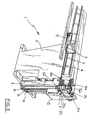
- the multi-function pipe bending machine of the invention has been generally identified by reference numeral 1.
- It comprises a base structure 2 to which, in a conventional and known manner, a carrage 3 horizontally movable on slide rails 4 is engaged.
- a carrage 3 horizontally movable on slide rails 4 is engaged.
- members 5 (partly shown in the figures) designed to support, rotate and lock a pipe 6 to be bent.
- the carriage 3 and the supported pipe 6 are disposed in cantilevered fashion on one side of the base structure 2.
- a bending head 7 comprising one support body defined by a slide 8 movable on first guides 9 integral to the base structure 2 and oriented horizontally along one traverse direction.
- a second support body Slidably engaged to the first slide 8 by means of second guides 10 integral to the first slide itself and oriented vertically along a second traverse direction perpendicular to said first direction, is a second support body defined by a second slide 11.
- the first and second slides, 8 and 11, are driven in motion along the respective guides by actuation means for example comprising the electric motors and first and second operating screws, 12 and 13, oriented parallelly to the first guides 9 and second guides 10, respectively.
- actuation means for example comprising the electric motors and first and second operating screws, 12 and 13, oriented parallelly to the first guides 9 and second guides 10, respectively.
- Two bending dies 14a and 14b can be positioned on the second slide 11. They are disposed spaced apart from each other in superposed relationship. Therefore an upper die 14a and a lower die 14b are available and they can be used selectively depending on working requirements.
- Two units 15a and 15b for positioning and locking the pipe 6 to be bent are provided in the vicinity of said dies. They are comprised respectively of an upper jaw 16a set in motion by an upper fluid-operated locking cylinder 17a and a lower jaw 16b set in motion by a lower fluid-operated locking cylinder 17b (Fig. 2).
- a bending device 18 rotatably movable about an axis coincident with the positioning axis of the dies 14a and 14b and comprising an upper pusher 19a and a lower pusher 19b, actuated by an upper fluid-operated bending cylinder 20a and a lower fluid-operated bending cylinder 20b and active on the pipe 6 against the action of dies 14a and 14b.
- the upper jaw 16a After positioning the pipe 6 on the support and locking means 5, the upper jaw 16a for example locks the pipe agaisnt the upper die 14a.
- the bending device 18 by rotating and pressing the pipe 6 by means of the upper pusher 19a, carries out one bending according to the intended angle (see Fig. 2).
- the second slide 11 is brought upwardly while the first slide 8 is caused to slide to the left so as to bring the bending head in register with the pipe to be bent.
- the pipe bending machine of the invention since the pipe bending machine of the invention has gripping members that are made movable in space by slides 8 and 11, it enables the same gripping members to be used as loading and positioning means for placing the pipes onto the supporting and locking elements 5. In this way the use of additional devices such as manipulators or robots for making the pipe supply steps automatic, can be avoided.
- the crossed movement in the horizontal and vertical directions of slides 8 and 11 can be utilized, when bending is over, for bringing the pipe to a near station, optionally mounted on the pipe bending machine itself, where a machining operation to the pipe ends, such as for example a flaring, tapering, narrowing or enlarging operation, the formation of a collar or the like is carried out. In this way it will be possible to machine the pipe ends while keeping the pipe mounted to the pipe bending machine.
- slides 8 and 11 Another opportunity offered by the presence of slides 8 and 11 is that of enabling a high-sensibility detection head, known per se and conventional, to be mounted on the machine. Close to said detection head, when the pipe is still mounted on the pipe bending machine, it is possible to carry out a precision control on the executed bending and the exact geometry of the workpiece.
Landscapes
- Engineering & Computer Science (AREA)
- Mechanical Engineering (AREA)
- Bending Of Plates, Rods, And Pipes (AREA)
Applications Claiming Priority (2)
| Application Number | Priority Date | Filing Date | Title |
|---|---|---|---|
| ITMI912737A IT1251934B (it) | 1991-10-16 | 1991-10-16 | Macchina curvatubi polifunzionale |
| ITMI912737 | 1991-10-16 |
Publications (3)
| Publication Number | Publication Date |
|---|---|
| EP0538207A2 true EP0538207A2 (de) | 1993-04-21 |
| EP0538207A3 EP0538207A3 (en) | 1993-06-30 |
| EP0538207B1 EP0538207B1 (de) | 1995-05-24 |
Family
ID=11360877
Family Applications (1)
| Application Number | Title | Priority Date | Filing Date |
|---|---|---|---|
| EP92830565A Expired - Lifetime EP0538207B1 (de) | 1991-10-16 | 1992-10-13 | Multi-funktionnelle Rohrbiegemaschine |
Country Status (5)
| Country | Link |
|---|---|
| US (1) | US5263350A (de) |
| EP (1) | EP0538207B1 (de) |
| DE (1) | DE69202678T2 (de) |
| ES (1) | ES2072742T3 (de) |
| IT (1) | IT1251934B (de) |
Cited By (9)
| Publication number | Priority date | Publication date | Assignee | Title |
|---|---|---|---|---|
| FR2758281A1 (fr) * | 1997-01-14 | 1998-07-17 | Robolix Sa | Machine a cintrer des tubes de faible diametre, notamment inferieurs a 10mm, predecoupes et presentant des systemes de raccord a chacune de leurs extremites, et tete de cintrage pour une telle machine |
| EP0990471A1 (de) * | 1998-09-30 | 2000-04-05 | FABBRICA MACCHINE CURVATUBI CRIPPA AGOSTINO S.p.A. | Biegemaschine |
| WO2000018527A1 (de) * | 1998-09-25 | 2000-04-06 | Pulzer Biegetechnik Gmbh | Gegenhaltevorrichtung für eine biegemaschine |
| EP1291094A1 (de) * | 2001-10-02 | 2003-03-12 | FABBRICA MACCHINE CURVATUBI CRIPPA AGOSTINO S.p.A. | Vorrichtung und Verfahren zum Ziehbiegen |
| EP1396295A1 (de) * | 2002-09-05 | 2004-03-10 | Trumpf Rohrtechnik GmbH + Co. KG | Biegemaschine mit Biegewerkzeugen an einander gegenüberliegenden Seiten eines Werkzeugträgers |
| EP1396294A1 (de) * | 2002-09-05 | 2004-03-10 | Trumpf Rohrtechnik GmbH + Co. KG | Biegemaschine mit Biegewerkzeugen an einander gegenüberliegenden Seiten eines Werkzeugträgers |
| US6715328B2 (en) * | 1998-09-25 | 2004-04-06 | Trumpf Pulzer Gmbh +Co. Kg | Bracing device for a bending machine |
| EP1914021A1 (de) | 2006-10-21 | 2008-04-23 | Felss Burger GmbH | Vorrichtung zum Biegen von stangen- und /oder stabartigen Werkstücken, insbesondere von Rohren sowie Biegewerkzeug für eine derartige Vorrichtung |
| CN108787818A (zh) * | 2018-07-17 | 2018-11-13 | 张家港市越泰精密机械有限公司 | 弯管机 |
Families Citing this family (21)
| Publication number | Priority date | Publication date | Assignee | Title |
|---|---|---|---|---|
| IT1290141B1 (it) * | 1997-03-21 | 1998-10-19 | Blm Spa | Macchina per curvare materiale filiforme come tubi barre o profilati |
| US7131312B2 (en) * | 2000-12-25 | 2006-11-07 | Yamaha Hatsudoki Kabushiki Kaisha | Pipe bending apparatus and method |
| US6655183B1 (en) * | 2002-07-16 | 2003-12-02 | Chiao Sheng Machinery Co., Ltd. | Lifting mechanism for a head member of a pipe bender |
| US7021102B2 (en) * | 2003-03-15 | 2006-04-04 | Trumpf Rohrtechnik Gmbh + Co. Kg | Bending machine with bending tools on opposite sides of a tool platen |
| EP1459816B1 (de) * | 2003-03-15 | 2006-09-06 | Trumpf Werkzeugmaschinen GmbH + Co. KG | Biegeeinrichtung mit Mehrniveaubiegewerkzeug sowie Spannbacken-und Gleitschienenstützeinheit für eine derartige Biegeeinrichtung |
| TWI243723B (en) * | 2004-06-08 | 2005-11-21 | Ying Lin Machine Ind Co Ltd | Dual-directional pipe-bending machine |
| US7254972B1 (en) * | 2006-06-28 | 2007-08-14 | Chia Sheng Machinery Co., Ltd. | Moving mold mechanism of a pipe bending machine |
| DE102008047542C5 (de) * | 2008-09-16 | 2016-02-18 | Tracto-Technik Gmbh & Co. Kg | Rohrbiegemaschine |
| EP3027334B1 (de) * | 2013-08-01 | 2018-05-16 | AddisonMckee, Inc. | Spannsystem für verbindungsstange |
| JP1525570S (de) * | 2014-11-26 | 2017-05-22 | ||
| JP1527322S (de) * | 2014-11-26 | 2017-06-05 | ||
| JP1525573S (de) * | 2014-11-26 | 2017-05-22 | ||
| JP1525574S (de) * | 2014-11-26 | 2017-05-22 | ||
| JP1525571S (de) * | 2014-11-26 | 2017-05-22 | ||
| US12204657B2 (en) * | 2019-11-22 | 2025-01-21 | Pure Storage, Inc. | Similar block detection-based detection of a ransomware attack |
| US12079502B2 (en) | 2019-11-22 | 2024-09-03 | Pure Storage, Inc. | Storage element attribute-based determination of a data protection policy for use within a storage system |
| US12248566B2 (en) * | 2019-11-22 | 2025-03-11 | Pure Storage, Inc. | Snapshot deletion pattern-based determination of ransomware attack against data maintained by a storage system |
| US12561428B2 (en) | 2019-11-22 | 2026-02-24 | Pure Storage, Inc. | Remote analysis of potentially corrupt data written to a storage system |
| US12153670B2 (en) | 2019-11-22 | 2024-11-26 | Pure Storage, Inc. | Host-driven threat detection-based protection of storage elements within a storage system |
| CN112536351A (zh) * | 2020-12-04 | 2021-03-23 | 奥美森智能装备股份有限公司 | 一种带移动功能的折弯机构及弯管机 |
| CN112453131A (zh) * | 2020-12-04 | 2021-03-09 | 奥美森智能装备股份有限公司 | 一种弯管机的弯管装置 |
Family Cites Families (13)
| Publication number | Priority date | Publication date | Assignee | Title |
|---|---|---|---|---|
| US3017917A (en) * | 1959-12-10 | 1962-01-23 | Pines Engineering Co Inc | Tube bending machine |
| US3299681A (en) * | 1960-03-22 | 1967-01-24 | Baldwin Lima Hamilton Corp | Program controlled tube bender |
| US3147792A (en) * | 1961-09-25 | 1964-09-08 | Charles F Hautau | Tube and bar bending machinery |
| US4112728A (en) * | 1975-08-22 | 1978-09-12 | Deutsche Babcock Aktiengesellschaft | Device for bending pipes |
| US4495788A (en) * | 1982-08-02 | 1985-01-29 | Eaton-Leonard Corporation | Multiple curvature bender |
| US5010758A (en) * | 1984-03-23 | 1991-04-30 | Chiyoda Kogyo Co., Ltd. | Bending machine |
| JPS61259836A (ja) * | 1985-05-14 | 1986-11-18 | Ishikawajima Harima Heavy Ind Co Ltd | チユ−ブの曲げ加工装置 |
| WO1987000775A1 (en) * | 1985-08-05 | 1987-02-12 | Gardner R F | Pipe bending machine |
| GB2187666B (en) * | 1986-03-15 | 1989-12-20 | Pressbend Ltd | Pipe bending apparatus |
| US4727738A (en) * | 1986-05-31 | 1988-03-01 | Kabushikikaisha Chuodenkiseisakusho | Bending apparatus |
| DE3618701A1 (de) * | 1986-06-04 | 1987-12-10 | Spaeth Gmbh & Co Kg Stahlbau B | Verfahren und vorrichtung zum kaltumformen von profilen aus eisen- und nichteisenmetallen |
| CA1317868C (en) * | 1989-10-05 | 1993-05-18 | Hideyuki Togoshi | Bending machine |
| CH683598A5 (de) * | 1990-03-13 | 1994-04-15 | Mewag Maschinenfabrik Ag | Rohrbiegemaschine. |
-
1991
- 1991-10-16 IT ITMI912737A patent/IT1251934B/it active IP Right Grant
-
1992
- 1992-10-13 ES ES92830565T patent/ES2072742T3/es not_active Expired - Lifetime
- 1992-10-13 DE DE69202678T patent/DE69202678T2/de not_active Expired - Lifetime
- 1992-10-13 US US07/960,009 patent/US5263350A/en not_active Expired - Lifetime
- 1992-10-13 EP EP92830565A patent/EP0538207B1/de not_active Expired - Lifetime
Cited By (12)
| Publication number | Priority date | Publication date | Assignee | Title |
|---|---|---|---|---|
| FR2758281A1 (fr) * | 1997-01-14 | 1998-07-17 | Robolix Sa | Machine a cintrer des tubes de faible diametre, notamment inferieurs a 10mm, predecoupes et presentant des systemes de raccord a chacune de leurs extremites, et tete de cintrage pour une telle machine |
| WO1998031484A1 (fr) * | 1997-01-14 | 1998-07-23 | Robolix | Machine a cintrer des tubes de faible diametre |
| US6185969B1 (en) | 1997-01-14 | 2001-02-13 | Robolix | Machine for bending tubes with small diameter |
| WO2000018527A1 (de) * | 1998-09-25 | 2000-04-06 | Pulzer Biegetechnik Gmbh | Gegenhaltevorrichtung für eine biegemaschine |
| US6715328B2 (en) * | 1998-09-25 | 2004-04-06 | Trumpf Pulzer Gmbh +Co. Kg | Bracing device for a bending machine |
| EP0990471A1 (de) * | 1998-09-30 | 2000-04-05 | FABBRICA MACCHINE CURVATUBI CRIPPA AGOSTINO S.p.A. | Biegemaschine |
| EP1291094A1 (de) * | 2001-10-02 | 2003-03-12 | FABBRICA MACCHINE CURVATUBI CRIPPA AGOSTINO S.p.A. | Vorrichtung und Verfahren zum Ziehbiegen |
| US6694794B2 (en) | 2001-10-02 | 2004-02-24 | Fabbrica Macchine Curvatubi Crippa Agostino S.P.A. | Draw-bending machine |
| EP1396295A1 (de) * | 2002-09-05 | 2004-03-10 | Trumpf Rohrtechnik GmbH + Co. KG | Biegemaschine mit Biegewerkzeugen an einander gegenüberliegenden Seiten eines Werkzeugträgers |
| EP1396294A1 (de) * | 2002-09-05 | 2004-03-10 | Trumpf Rohrtechnik GmbH + Co. KG | Biegemaschine mit Biegewerkzeugen an einander gegenüberliegenden Seiten eines Werkzeugträgers |
| EP1914021A1 (de) | 2006-10-21 | 2008-04-23 | Felss Burger GmbH | Vorrichtung zum Biegen von stangen- und /oder stabartigen Werkstücken, insbesondere von Rohren sowie Biegewerkzeug für eine derartige Vorrichtung |
| CN108787818A (zh) * | 2018-07-17 | 2018-11-13 | 张家港市越泰精密机械有限公司 | 弯管机 |
Also Published As
| Publication number | Publication date |
|---|---|
| IT1251934B (it) | 1995-05-27 |
| EP0538207B1 (de) | 1995-05-24 |
| US5263350A (en) | 1993-11-23 |
| EP0538207A3 (en) | 1993-06-30 |
| ES2072742T3 (es) | 1995-07-16 |
| DE69202678T2 (de) | 1995-10-19 |
| ITMI912737A0 (it) | 1991-10-16 |
| ITMI912737A1 (it) | 1993-04-16 |
| DE69202678D1 (de) | 1995-06-29 |
Similar Documents
| Publication | Publication Date | Title |
|---|---|---|
| US5263350A (en) | Multi-function pipe bending machine | |
| CA1320870C (en) | Manipulator device for a bending machine and a method for changing the position of the workpiece in a bending process | |
| US4637108A (en) | Pallet changer | |
| US7104100B2 (en) | Bending device for tube | |
| CN208583845U (zh) | 一种全自动钣金折弯机 | |
| US5099670A (en) | Plate bending machine | |
| EP0592798B1 (de) | Verfahren zum Biegen und Vorrichtung dafür | |
| JPS6268625A (ja) | 曲げ加工プレス機 | |
| US3431759A (en) | Forming apparatus | |
| JP5785031B2 (ja) | パレット交換システム及び当該システムを備えたマシニングセンタ | |
| US3496747A (en) | Numerically controlled spinning machine | |
| CN108465717B (zh) | 一种全自动钣金折弯机 | |
| US5010758A (en) | Bending machine | |
| US5042279A (en) | Bending machine | |
| JP4112233B2 (ja) | 工作機械におけるワーククランプ装置 | |
| CN118559450A (zh) | 一种排气法兰加工定位工装 | |
| US20220143666A1 (en) | Tool and method for processing plate-shaped workpieces, in particular metal sheets | |
| JP3618162B2 (ja) | プレス装置 | |
| JPH0197542A (ja) | パレット交換方法 | |
| JP2531034B2 (ja) | 薄板の成形金型 | |
| JP2006305692A (ja) | 工作機械 | |
| US5489089A (en) | Automatic alignmant vise | |
| JP3637658B2 (ja) | 金属パイプ曲げ加工装置 | |
| JPH0710819Y2 (ja) | 転造盤構造 | |
| JPS6326221A (ja) | パイプベンダ− |
Legal Events
| Date | Code | Title | Description |
|---|---|---|---|
| PUAI | Public reference made under article 153(3) epc to a published international application that has entered the european phase |
Free format text: ORIGINAL CODE: 0009012 |
|
| AK | Designated contracting states |
Kind code of ref document: A2 Designated state(s): CH DE ES FR GB IT LI NL SE |
|
| PUAL | Search report despatched |
Free format text: ORIGINAL CODE: 0009013 |
|
| AK | Designated contracting states |
Kind code of ref document: A3 Designated state(s): CH DE ES FR GB IT LI NL SE |
|
| 17P | Request for examination filed |
Effective date: 19930721 |
|
| 17Q | First examination report despatched |
Effective date: 19940628 |
|
| GRAA | (expected) grant |
Free format text: ORIGINAL CODE: 0009210 |
|
| ITF | It: translation for a ep patent filed | ||
| AK | Designated contracting states |
Kind code of ref document: B1 Designated state(s): CH DE ES FR GB IT LI NL SE |
|
| PG25 | Lapsed in a contracting state [announced via postgrant information from national office to epo] |
Ref country code: NL Free format text: LAPSE BECAUSE OF FAILURE TO SUBMIT A TRANSLATION OF THE DESCRIPTION OR TO PAY THE FEE WITHIN THE PRESCRIBED TIME-LIMIT Effective date: 19950524 Ref country code: LI Effective date: 19950524 Ref country code: CH Effective date: 19950524 |
|
| REF | Corresponds to: |
Ref document number: 69202678 Country of ref document: DE Date of ref document: 19950629 |
|
| ET | Fr: translation filed | ||
| REG | Reference to a national code |
Ref country code: ES Ref legal event code: FG2A Ref document number: 2072742 Country of ref document: ES Kind code of ref document: T3 |
|
| PG25 | Lapsed in a contracting state [announced via postgrant information from national office to epo] |
Ref country code: SE Effective date: 19950824 |
|
| REG | Reference to a national code |
Ref country code: CH Ref legal event code: PL |
|
| NLV1 | Nl: lapsed or annulled due to failure to fulfill the requirements of art. 29p and 29m of the patents act | ||
| PLBE | No opposition filed within time limit |
Free format text: ORIGINAL CODE: 0009261 |
|
| 26N | No opposition filed | ||
| REG | Reference to a national code |
Ref country code: GB Ref legal event code: IF02 |
|
| PGFP | Annual fee paid to national office [announced via postgrant information from national office to epo] |
Ref country code: GB Payment date: 20101029 Year of fee payment: 19 Ref country code: IT Payment date: 20101026 Year of fee payment: 19 |
|
| PGFP | Annual fee paid to national office [announced via postgrant information from national office to epo] |
Ref country code: ES Payment date: 20111124 Year of fee payment: 20 Ref country code: FR Payment date: 20111115 Year of fee payment: 20 |
|
| PGFP | Annual fee paid to national office [announced via postgrant information from national office to epo] |
Ref country code: DE Payment date: 20120102 Year of fee payment: 20 |
|
| REG | Reference to a national code |
Ref country code: DE Ref legal event code: R071 Ref document number: 69202678 Country of ref document: DE |
|
| REG | Reference to a national code |
Ref country code: DE Ref legal event code: R071 Ref document number: 69202678 Country of ref document: DE |
|
| REG | Reference to a national code |
Ref country code: GB Ref legal event code: PE20 Expiry date: 20121012 |
|
| PG25 | Lapsed in a contracting state [announced via postgrant information from national office to epo] |
Ref country code: GB Free format text: LAPSE BECAUSE OF EXPIRATION OF PROTECTION Effective date: 20121012 |
|
| REG | Reference to a national code |
Ref country code: ES Ref legal event code: FD2A Effective date: 20130718 |
|
| PG25 | Lapsed in a contracting state [announced via postgrant information from national office to epo] |
Ref country code: ES Free format text: LAPSE BECAUSE OF EXPIRATION OF PROTECTION Effective date: 20121014 |