EP0538593B1 - Papier-Zuführvorrichtung und Kassette hierfür - Google Patents
Papier-Zuführvorrichtung und Kassette hierfür Download PDFInfo
- Publication number
- EP0538593B1 EP0538593B1 EP92114784A EP92114784A EP0538593B1 EP 0538593 B1 EP0538593 B1 EP 0538593B1 EP 92114784 A EP92114784 A EP 92114784A EP 92114784 A EP92114784 A EP 92114784A EP 0538593 B1 EP0538593 B1 EP 0538593B1
- Authority
- EP
- European Patent Office
- Prior art keywords
- media
- load plate
- arm
- paper
- plate
- Prior art date
- Legal status (The legal status is an assumption and is not a legal conclusion. Google has not performed a legal analysis and makes no representation as to the accuracy of the status listed.)
- Expired - Lifetime
Links
Images




Classifications
-
- B—PERFORMING OPERATIONS; TRANSPORTING
- B65—CONVEYING; PACKING; STORING; HANDLING THIN OR FILAMENTARY MATERIAL
- B65H—HANDLING THIN OR FILAMENTARY MATERIAL, e.g. SHEETS, WEBS, CABLES
- B65H1/00—Supports or magazines for piles from which articles are to be separated
- B65H1/08—Supports or magazines for piles from which articles are to be separated with means for advancing the articles to present the articles to the separating device
- B65H1/12—Supports or magazines for piles from which articles are to be separated with means for advancing the articles to present the articles to the separating device comprising spring
-
- B—PERFORMING OPERATIONS; TRANSPORTING
- B41—PRINTING; LINING MACHINES; TYPEWRITERS; STAMPS
- B41J—TYPEWRITERS; SELECTIVE PRINTING MECHANISMS, i.e. MECHANISMS PRINTING OTHERWISE THAN FROM A FORME; CORRECTION OF TYPOGRAPHICAL ERRORS
- B41J13/00—Devices or arrangements of selective printing mechanisms, e.g. ink-jet printers or thermal printers, specially adapted for supporting or handling copy material in short lengths, e.g. sheets
- B41J13/10—Sheet holders, retainers, movable guides, or stationary guides
- B41J13/103—Sheet holders, retainers, movable guides, or stationary guides for the sheet feeding section
-
- B—PERFORMING OPERATIONS; TRANSPORTING
- B65—CONVEYING; PACKING; STORING; HANDLING THIN OR FILAMENTARY MATERIAL
- B65H—HANDLING THIN OR FILAMENTARY MATERIAL, e.g. SHEETS, WEBS, CABLES
- B65H1/00—Supports or magazines for piles from which articles are to be separated
- B65H1/04—Supports or magazines for piles from which articles are to be separated adapted to support articles substantially horizontally, e.g. for separation from top of pile
-
- B—PERFORMING OPERATIONS; TRANSPORTING
- B65—CONVEYING; PACKING; STORING; HANDLING THIN OR FILAMENTARY MATERIAL
- B65H—HANDLING THIN OR FILAMENTARY MATERIAL, e.g. SHEETS, WEBS, CABLES
- B65H1/00—Supports or magazines for piles from which articles are to be separated
- B65H1/26—Supports or magazines for piles from which articles are to be separated with auxiliary supports to facilitate introduction or renewal of the pile
- B65H1/266—Support fully or partially removable from the handling machine, e.g. cassette, drawer
-
- B—PERFORMING OPERATIONS; TRANSPORTING
- B65—CONVEYING; PACKING; STORING; HANDLING THIN OR FILAMENTARY MATERIAL
- B65H—HANDLING THIN OR FILAMENTARY MATERIAL, e.g. SHEETS, WEBS, CABLES
- B65H2511/00—Dimensions; Position; Numbers; Identification; Occurrences
- B65H2511/10—Size; Dimensions
-
- B—PERFORMING OPERATIONS; TRANSPORTING
- B65—CONVEYING; PACKING; STORING; HANDLING THIN OR FILAMENTARY MATERIAL
- B65H—HANDLING THIN OR FILAMENTARY MATERIAL, e.g. SHEETS, WEBS, CABLES
- B65H2511/00—Dimensions; Position; Numbers; Identification; Occurrences
- B65H2511/10—Size; Dimensions
- B65H2511/11—Length
-
- B—PERFORMING OPERATIONS; TRANSPORTING
- B65—CONVEYING; PACKING; STORING; HANDLING THIN OR FILAMENTARY MATERIAL
- B65H—HANDLING THIN OR FILAMENTARY MATERIAL, e.g. SHEETS, WEBS, CABLES
- B65H2511/00—Dimensions; Position; Numbers; Identification; Occurrences
- B65H2511/20—Location in space
- B65H2511/22—Distance
Definitions
- This invention relates to a paper cassette which contains cutforms and other media which are supplied to terminal devices such as printers.
- a device to automatically supply media to terminal devices such as printers was disclosed in Japanese Patent Application Laid-open No. 218238/1985.
- terminal devices such as printers
- Media are stored in and supplied from these hoppers.
- Figure 1 is a partially cut-away side view showing the conventional paper feed device.
- Media 2 is stacked and stored in hopper or cassette 3, which is installed in automatic paper feed device 1.
- Printer 4 is placed on top of automatic paper feed device 1.
- Supply roller 5 is installed above cassette 3 and feed roller 6 is also disposed inside the device.
- spring 7 is provided underneath media 2.
- Cassette container 9 is installed to the side of automatic paper feed device 1 and printer 4.
- Cassette container 9 contains cassettes 8 which store specific sizes of media which are not in use.
- the operation of the conventional automatic paper feed device will be explained next.
- the media 2 which is stacked and stored in cassette 3 is pushed by spring 7 into contact with supply roller 5.
- Supply roller 5 is rotated in the direction of arrow G by a drive means not shown, and this causes the media to begin to be fed from the top, one sheet at a time.
- Media 2, which has begun to be fed, is sent to printer 4 by feed roller 6.
- cassette 3 When one wishes to print media which is different in size from media 2 (stacked and stored in cassette 3) with printer 4, one takes cassette 3 out of automatic paper feed device 1.
- Cassette 8 in which is stored the media of the size desired, is then taken out of cassette container 9 and installed in automatic paper feed device 1. Paper feed to printer 4 may then be performed.
- Cassette 3, which has been taken out of automatic paper feed device 1 is then stored in cassette container 9. By manual input instructions are sent to printer 4 concerning the size of the media newly installed in automatic paper feed device 1.
- a single paper cassette suitable for different sizes of paper is disclosed in the document DE-A-33 31 077. It comprises a media load plate positioning the paper by a back edge guide assembly, which is in particular capable for obtaining the paper size and providing electrical signals according to the paper size.
- DE-A-24 16 782 is concerned with a paper cassette comprising in particular a turnable paper load plate and some guide members.
- US-A-4 307 878 discloses a cassette type feed apparatus using a spring system which is adjustable under the control of an indexing member to adjust the bias in accordance with the paper size.
- the spring system includes a first spring which is operable with different sizes of paper sheet and a second spring which is enabled only when the cassette contains large sheets.
- DE 33 30 868 discloses a further paper feed cassette comprising a spring biased member which lifts the base plate loaded with the paper.
- the lifting is adjustable by means of a paper-bias control which could be moved in the cross direction of the paper feed direction.
- the thickness of the paper-bias control varies along its length in order to allow the adjustment of the bias pressure to be adjusted depending on its position in cross direction.
- An object of this invention is to solve the problems described above, making it possible for the installation area to be smaller and providing an inexpensive automatic paper feed device of excellent operability.
- Another object of this invention is to provide a paper cassette from which can be obtained a pressure appropriate to the size of the media in question, and which is able thereby to feed media with stability.
- the paper cassette stores a large media and the media load plate is raised by a reset arm and this causes a sub-arm to rotate following the reset arm. This in turn causes an auxiliary resilient member to push up the reset arm and media load plate.
- the pressure by which the media is pushed against the hopping roller is therefore the combined upward pushing force of the coil springs and the auxiliary resilient member.
- the sub-arm When a smaller media is stored, the sub-arm is prevented from rotating even though the media load plate is pushed up by the reset arm. Therefore, because the auxiliary resilient member is separated from the reset arm, the upward pushing force of the auxiliary resilient member is not transmitted to the media load plate. The pressure pushing the media against the hopping roller is therefore only the upward pushing force of the coil springs.
- the paper cassette stores a large media and the media load plate is raised by a reset arm and this causes an auxiliary resilient member to rotate following the reset arm. This in turn causes the auxiliary resilient member to push up the reset arm and media load plate.
- the pressure by which the media is pushed against the hopping roller is therefore the combined upward pushing force of the coil springs and the auxiliary resilient member.
- the auxiliary resilient member When a smaller media is stored, the auxiliary resilient member does not rotate even though the media load plate is pushed up by the reset arm. Therefore, the upward pushing force of the auxiliary resilient member is not transmitted to the reset arm media load plate. The pressure pushing the media against the hopping roller is therefore only the upward pushing force of the coil springs.
- Figure 2 is a cut-away perspective drawing of a paper cassette according to this embodiment.
- Figure 3 is a front view showing the state of a paper cassette according to this embodiment when it is installed in a paper feed device.
- Paper cassette 301 is attached so that L-shaped media load plate 306 is able to rotate with fulcrum 307 as center.
- a pair of flanges 308 are formed in the front bottom of media load plate 306.
- Shaft 310 is inserted into oval holes 309 so that it is able to slide.
- Both ends of shaft 310 are attached to reset arm 332.
- reset arm 332 is attached through shaft 310 to the front bottom of media load plate 306.
- Media back edge guide plate 314 is also attached to the back of media load plate 306.
- Media back edge guide plate 314 positions the media loaded on media load plate 306 in the feed direction. In order to respond to the size of the media, media back edge guide plate 314 is able to move along guide rail 315, which is formed in the feed direction.
- a pair of coil springs 323a and 323b are mounted in the front bottom area of media load plate 306 in the space between it and bottom plate 317.
- the force with which said coil springs 323a and 323b push up media load plate 306 is set to a pressure appropriate for pushing smaller media against hopping roller, not shown, when they are stored on media load plate 306.
- Reset arm 332 is attached at two points to shaft 313 journalled by frame 312 of cassette 301. Reset arm 332 is provided with an opening 333. Attached to shaft 313 on both sides of reset arm 332 is torsion spring 334, which is the auxiliary resilient member. The torsion spring 334 is bent around the back of reset arm 332 and constantly energizes reset arm 332 upwards.
- sub-arm 335 is attached to shaft 313 in between the attachment points of reset arm 332.
- a U-shaped cutout 336 is formed on one end of sub-arm 335. This cutout holds torsion spring 334 in the bottom of opening 333.
- L-shaped protrusion 337 is formed on the other end of sub-arm 335. Clearance opening 338 is formed in the position on bottom plate 317 where the protrusion 337 moves to when sub-arm 335 rotates in the direction shown by arrow D in Figure 2. This makes it possible for sub-arm 335 to rotate further.
- Bracket 339 is provided on the bottom of the shaft 313.
- Shaft 313 is installed between U-shaped holes 340a and 340b of bracket 339.
- the tip of arm section 341 of bracket 339 goes into hole 342 provided on side plate 316a. Therefore, when side plate 316a moves according to the size of the media, it is accompanied by bracket 339 which thereby moves parallel to shaft 313.
- Plate 343 is also provided on bracket 339. Opening 344 is provided on plate 343 in a position which overlaps the position of clearance hole 338 on bottom plate 317 when bracket 339 is moved to store a wide media.
- a wide media is now set and paper cassette 301 is returned to the paper feed device.
- the unshown locking means described above is released. This causes media load plate 306 to be rotated and raised by a pair of coil springs 323a and 323b.
- the direction of rotation is opposite to that shown by arrow B and fulcrum 307 is the center.
- Reset arm 332 also rotates in the direction shown by arrow D to accompany this movement with shaft 313 as center.
- Opening 344 of bracket 339 and clearance hole 338 of bottom plate 317 are positioned in the rotation range of protrusion 337 at this time, making even more rotation possible.
- torsion spring 334 which is inside groove 336 of sub-lever 335, rotates with shaft 313 as center so that it follows the rotation of reset arm 332.
- the top of the media is pushed against hopping roller, and though the rotation of reset arm 332 is stopped, torsion spring 334 pushes farther up from the back of reset arm 332. This upward pushing force becomes a force pushing up media load plate 306.
- Figure 3 is a cut-away perspective view showing the lowered state of the media load plate 306.
- Figure 4 is a cut-away perspective view showing the raised state of the media load plate 306. The operations up to the point where media load plate 306 is lowered and side plates 316a and 316b and media back edge guide plate 314 are moved to fit the size of the media are the same as those described above and will therefore be omitted.
- Bracket 339 moves parallel to shaft 313 to accompany the movement of side plate 316a. Because protrusion 337 of sub-arm 335 is separated from plate 343 of bracket 339 at this time, bracket 339 is able to move smoothly. As shown in Figure 3, bracket 339 moves until plate 343 is in a position over clearance hole 338 of bottom plate 317. A smaller media is then stored on media load plate 306.
- the pressure pushing the top of the media against the hopping roller is a pressure appropriate for the feeding of smaller media.
- the paper feed operation is the same as for the feeding of larger media.
- a torsion spring was used as the auxiliary resilient member energizing the reset arm. It is, of course, possible to use something other than this, a plate spring, for example.
- Figure 5 is a cut-away perspective drawing of a paper cassette according to this embodiment.
- Figure 6 is a front view showing the state of this embodiment of a paper cassette when it is installed in a paper feed device.
- Tip 433 of torsion spring 432 is bent downwards in an L-shape around the back of reset arm 411 and constantly energizes reset arm 411 upwards.
- Convex member 434 is formed integrally in side plate 416a facing bottom plate 417. Opening 435 is provided in the front part of bottom plate 417.
- Sub-arm 315 and clearance opening 338 of the embodiment of Figure 2 through Figure 4 are omitted.
- shaft 413 is first rotated in the direction shown by arrow A by a lever not shown in the drawings. This causes reset arm 411 to rotate in the direction shown by arrow D with shaft 413 as its center. Media load plate 406 then rotates in the direction shown by arrow B with fulcrum 407 as its center and is lowered. The rotation of reset arm 411 causes torsion spring 432 to rotate in the same direction. When reset arm 411 has rotated to a specified position it is held in that state by a holding means not shown in the drawings. At this time tip 433 of torsion spring 432 enters opening 435 provided on bottom plate 417. Torsion spring 432 is located below bottom plate 417. Cassette 431 is pulled out from the device in this state.
- Media back edge guide plate 414 is moved along guide rail 415 to the length of the media.
- Side plate 416a is also moved to fit the length of the media in the width direction.
- side plate 416b is moved by pinion 420 the same distance in the opposite direction.
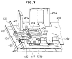
- Figure 7 is a cut-away perspective drawing showing the state in which the media load plate is lowered.
- Figure 8 is a cut-away perspective drawing showing the state in which the media load plate is raised.
- media load plate 406 of paper cassette 431 which has been pulled out of the paper feed device in order to set the media, is lowered as shown in Figure 7, and tip 433 of torsion spring 432 is in opening 435.
- Media back edge guide plate 414 and side plates 416a and 416b are moved respectively to the length in the direction of paper feed and the width of the media.
- the movement of side plate 416a causes convex member 434 to move to a position above opening 435 of bottom plate 417.
- a small media is then loaded on media load plate 406 and set, and cassette 431 is returned to device 402.
- shaft 413 is rotated in the direction shown by arrow E in Figure 5 by a lever not shown in the drawings, and reset arm 411 is released.
- This causes media load plate 406 to be rotated and raised by a pair of coil springs 423a and 423b.
- the direction of rotation is shown by arrow F in Figure 8 and fulcrum 407 is the center.
- Reset arm 411 also rotates upwards with shaft 413 as center, being pulled up by media load plate 406.
- torsion spring 432 also rotates following the rotation of reset arm 411.
- tip 433 strikes the convex member 434 and torsion spring 432 is prevented from rotating.
- reset arm 411 and torsion spring 432 separate.
- the force pushing up media load plate 406 is only the upward pushing force of coil springs 423a and 423b.
- the pressure pushing the top of the media against hopping roller 403 is a pressure appropriate for the feeding of smaller media.
- the hopping roller 403 is rotated, and the media is separated into sheets by separation claws 421a and 421b. The paper feed is thereby performed.
- the torsion spring 432 has a tip 433 which is bent downwards in an L-shape, and torsion spring 432 is attached to shaft 413.
- convex member 434 of the embodiment of Figure 5 through Figure 8 convex member 441, bent upwards in an L-shape, has been formed integrally with side plate 416a.
- convex member 441 When a large media is stored on it, convex member 441 is separated from tip 433 of torsion spring 432 by the movement of side plate 416a. This causes torsion spring 432 to be able to rotate freely. When a small media is stored on it, convex member 441 moves so that it covers the top of tip 433 of torsion spring 432, preventing torsion spring 432 from rotating. Therefore the same effects are obtainable as from the embodiment of Figure 5 through Figure 8. Furthermore, because there is no need to provide an opening on the bottom plate of the cassette in the above embodiment, it has the effect of simplifying the structure.
- the above-described embodiments make it possible to obtain a large upward pushing force for wider media as well as an appropriate force for narrower media. Therefore, the pressure with which the top of the media is pushed against the hopping roller will be a pressure appropriate to the size of the media. This will eliminate double feeding and feeding misses generated during feeding due to the differences in media size.
- a paper cassette which is able to perform feeding in a stable manner may be provided with a simple parts structure and at an inexpensive cost.
Landscapes
- Engineering & Computer Science (AREA)
- Mechanical Engineering (AREA)
- Sheets, Magazines, And Separation Thereof (AREA)
Claims (2)
- Papierkassette, welche eine Anzahl von Typen eines Mediums auf eine Medium-Ladeplatte (306) speichert, wobei ein Ende der Medium-Ladeplatte (306) in einer solchen Weise drehbar gelagert ist, daß sie sich drehen kann, und das andere Ende von einem Rücksetzarm (332) herauf- und heruntergedreht wird,
das Medium entsprechend seiner Breite durch Bewegen einer Seitenplatte (316a, b) positioniert wird,
die Papiereinspeisung durchgeführt wird, indem das Medium gegen eine Einspeiswalze gedrückt wird,
das Medium gedrückt wird durch Drücken des oberen Endes der Mediumlade-Platte mittels Federn (323a, b),
gekennzeichnet durch
ein nachgiebiges Hilfsteil (334), welches in der Lage ist, mit dem Rücksetzarm sich zu drehen und den Rücksetzarm (332) zu drücken, und
eine Einrichtung (339, 343), welche mit der Seitenplatte integriert ausgebildet ist und welche die Drehung des nachgiebigen Hilfsteils (334) entsprechend der Größe des Mediums reguliert. - Papierkassette nach Anspruch 1, gekennzeichnet durch einen Unterarm (335), dessen eines Ende an dem nachgiebigen Hilfsteil (334) anliegt und dieses anhält, wobei
der Unterarm (335) zusammen mit dem nachgiebigen Hilfsteil (334) sich dreht,
die Einrichtung (339, 343) zum Regulieren der Drehung des nachgiebigen Hilfsteils (334) im Drehbereich des Unterarms (335) vorgesehen ist und in der Lage ist, sich in Übereinstimmung mit der Größe des Mediums zu bewegen.
Applications Claiming Priority (11)
| Application Number | Priority Date | Filing Date | Title |
|---|---|---|---|
| JP92029/87 | 1987-04-16 | ||
| JP1987056711U JPH0628503Y2 (ja) | 1987-04-16 | 1987-04-16 | 自動給紙装置の用紙カセツト |
| JP62092029A JPH0626985B2 (ja) | 1987-04-16 | 1987-04-16 | 自動給紙装置 |
| JP56711/87U | 1987-04-16 | ||
| JP57534/87U | 1987-04-17 | ||
| JP1987057534U JPH0542983Y2 (de) | 1987-04-17 | 1987-04-17 | |
| JP1987070911U JPH0542984Y2 (de) | 1987-05-14 | 1987-05-14 | |
| JP70911/87U | 1987-05-14 | ||
| JP7987387U JPS63190232U (de) | 1987-05-28 | 1987-05-28 | |
| JP79873/87U | 1987-05-28 | ||
| EP88105714A EP0287915B1 (de) | 1987-04-16 | 1988-04-11 | Papiertransporteinrichtung und Papierkassette dafür |
Related Parent Applications (1)
| Application Number | Title | Priority Date | Filing Date |
|---|---|---|---|
| EP88105714.5 Division | 1988-04-11 |
Publications (2)
| Publication Number | Publication Date |
|---|---|
| EP0538593A1 EP0538593A1 (de) | 1993-04-28 |
| EP0538593B1 true EP0538593B1 (de) | 1994-11-02 |
Family
ID=27523315
Family Applications (3)
| Application Number | Title | Priority Date | Filing Date |
|---|---|---|---|
| EP92114785A Expired - Lifetime EP0523748B1 (de) | 1987-04-16 | 1988-04-11 | Papierkassette |
| EP88105714A Expired - Lifetime EP0287915B1 (de) | 1987-04-16 | 1988-04-11 | Papiertransporteinrichtung und Papierkassette dafür |
| EP92114784A Expired - Lifetime EP0538593B1 (de) | 1987-04-16 | 1988-04-11 | Papier-Zuführvorrichtung und Kassette hierfür |
Family Applications Before (2)
| Application Number | Title | Priority Date | Filing Date |
|---|---|---|---|
| EP92114785A Expired - Lifetime EP0523748B1 (de) | 1987-04-16 | 1988-04-11 | Papierkassette |
| EP88105714A Expired - Lifetime EP0287915B1 (de) | 1987-04-16 | 1988-04-11 | Papiertransporteinrichtung und Papierkassette dafür |
Country Status (3)
| Country | Link |
|---|---|
| US (1) | US4874159A (de) |
| EP (3) | EP0523748B1 (de) |
| DE (3) | DE3883587T2 (de) |
Families Citing this family (19)
| Publication number | Priority date | Publication date | Assignee | Title |
|---|---|---|---|---|
| JP3116448B2 (ja) * | 1991-09-13 | 2000-12-11 | ブラザー工業株式会社 | 給紙カセット |
| US5320338A (en) * | 1992-02-14 | 1994-06-14 | Mita Industrial Co., Ltd. | Cassette |
| GB9300806D0 (en) * | 1993-01-16 | 1993-03-10 | Keegan Roger N | Print tray adaptor |
| JP3168127B2 (ja) * | 1993-11-24 | 2001-05-21 | キヤノン株式会社 | シート積載装置及び画像形成装置 |
| EP0722839A3 (de) * | 1995-01-17 | 1998-01-07 | Hewlett-Packard Company | Tintenstrahldrucker mit grossvolumigem Hilfseingabefach |
| JPH08333026A (ja) * | 1995-06-09 | 1996-12-17 | Seiko Epson Corp | プリンタ |
| CA2360253C (en) * | 2000-11-01 | 2005-08-02 | Lg Electronics Inc. | Media cassette for automatic dispenser |
| KR20010016091A (ko) * | 2000-11-01 | 2001-03-05 | 구자홍 | 매체카세트장치 |
| JP2004091066A (ja) * | 2002-08-29 | 2004-03-25 | Sharp Corp | 給紙カセット |
| US7357586B2 (en) * | 2005-04-14 | 2008-04-15 | Samsung Electronics Co., Ltd. | Image forming apparatus including a paper feeding cassette |
| US20060244197A1 (en) * | 2005-04-29 | 2006-11-02 | Ecrm Incorporated | System and method for holding imaging plates and/or delivering imaging plates to an imaging system |
| JP4533241B2 (ja) * | 2005-05-25 | 2010-09-01 | キヤノン株式会社 | シート給送装置および画像形成装置 |
| JP4207041B2 (ja) * | 2005-12-28 | 2009-01-14 | ブラザー工業株式会社 | 用紙ガイド装置及び画像形成装置 |
| JP5335457B2 (ja) * | 2009-01-29 | 2013-11-06 | キヤノン株式会社 | シート給送装置及び画像形成装置 |
| JP5641731B2 (ja) * | 2009-12-16 | 2014-12-17 | キヤノン株式会社 | シート給送装置及び画像形成装置 |
| JP6185244B2 (ja) * | 2013-01-08 | 2017-08-23 | サトーホールディングス株式会社 | 用紙ガイド機構 |
| JP5842868B2 (ja) * | 2013-06-18 | 2016-01-13 | コニカミノルタ株式会社 | 給紙カセット |
| JP7845033B2 (ja) * | 2022-05-10 | 2026-04-14 | セイコーエプソン株式会社 | 給送カセット及び記録装置 |
| JP2025058706A (ja) * | 2023-09-28 | 2025-04-09 | キヤノン株式会社 | シート積載装置 |
Citations (2)
| Publication number | Priority date | Publication date | Assignee | Title |
|---|---|---|---|---|
| DE3330868A1 (de) * | 1982-08-31 | 1984-03-01 | Konishiroku Photo Industry Co., Ltd., Tokyo | Universal-papier(vorrats)kassette |
| US4697803A (en) * | 1984-05-15 | 1987-10-06 | Sanyo Electric Co., Ltd. | Sheet member feeding cassette |
Family Cites Families (13)
| Publication number | Priority date | Publication date | Assignee | Title |
|---|---|---|---|---|
| US3153534A (en) * | 1959-07-02 | 1964-10-20 | Xerox Corp | Paper supply tray |
| GB1419507A (en) * | 1972-12-01 | 1975-12-31 | Rank Xerox Ltd | Sheet feeding devices |
| US4032136A (en) * | 1973-04-06 | 1977-06-28 | Canon Kabushiki Kaisha | Feed cassette |
| JPS49127632A (de) * | 1973-04-06 | 1974-12-06 | ||
| DE2715948C3 (de) * | 1977-04-09 | 1979-10-11 | Hoechst Ag, 6000 Frankfurt | Kassette |
| JPS5584731A (en) * | 1978-12-15 | 1980-06-26 | Canon Inc | Feed cassette |
| JPS55119638A (en) * | 1979-03-06 | 1980-09-13 | Minolta Camera Co Ltd | Paper loading plate push-up-type cassette paper feeder |
| JPS5939629A (ja) * | 1982-08-31 | 1984-03-05 | Konishiroku Photo Ind Co Ltd | 給紙用ユニバ−サルカセツト |
| JPS59190128A (ja) * | 1983-04-12 | 1984-10-27 | Mita Ind Co Ltd | 複写機の給紙装置 |
| JPS60173536A (ja) * | 1984-02-20 | 1985-09-06 | Toshiba Corp | 画情報読取装置 |
| JPS60218238A (ja) * | 1984-04-16 | 1985-10-31 | Oki Electric Ind Co Ltd | 自動給紙装置 |
| US4780740A (en) * | 1985-04-02 | 1988-10-25 | Kentek Information Systems, Inc. | Paper feeding cassette for a printing apparatus |
| US4786042A (en) * | 1987-04-01 | 1988-11-22 | Xerox Corporation | Adjustable size sensing sheet cassette |
-
1988
- 1988-04-11 EP EP92114785A patent/EP0523748B1/de not_active Expired - Lifetime
- 1988-04-11 DE DE88105714T patent/DE3883587T2/de not_active Expired - Lifetime
- 1988-04-11 DE DE3852768T patent/DE3852768T2/de not_active Expired - Lifetime
- 1988-04-11 EP EP88105714A patent/EP0287915B1/de not_active Expired - Lifetime
- 1988-04-11 DE DE3852043T patent/DE3852043T2/de not_active Expired - Lifetime
- 1988-04-11 EP EP92114784A patent/EP0538593B1/de not_active Expired - Lifetime
- 1988-04-15 US US07/182,230 patent/US4874159A/en not_active Expired - Lifetime
Patent Citations (2)
| Publication number | Priority date | Publication date | Assignee | Title |
|---|---|---|---|---|
| DE3330868A1 (de) * | 1982-08-31 | 1984-03-01 | Konishiroku Photo Industry Co., Ltd., Tokyo | Universal-papier(vorrats)kassette |
| US4697803A (en) * | 1984-05-15 | 1987-10-06 | Sanyo Electric Co., Ltd. | Sheet member feeding cassette |
Non-Patent Citations (1)
| Title |
|---|
| Patents Abstracts of Japan vol. 10, no. 77(M-464)(2134) 26 March 1086 * |
Also Published As
| Publication number | Publication date |
|---|---|
| DE3883587T2 (de) | 1993-12-16 |
| US4874159A (en) | 1989-10-17 |
| EP0523748A1 (de) | 1993-01-20 |
| EP0538593A1 (de) | 1993-04-28 |
| DE3852768T2 (de) | 1995-05-18 |
| DE3852768D1 (de) | 1995-02-23 |
| DE3852043D1 (de) | 1994-12-08 |
| EP0287915A3 (en) | 1990-04-11 |
| EP0287915B1 (de) | 1993-09-01 |
| EP0523748B1 (de) | 1995-01-11 |
| DE3852043T2 (de) | 1995-03-09 |
| EP0287915A2 (de) | 1988-10-26 |
| DE3883587D1 (de) | 1993-10-07 |
Similar Documents
| Publication | Publication Date | Title |
|---|---|---|
| EP0538593A1 (de) | Papier-Zuführvorrichtung und Kassette hierfür | |
| US5913510A (en) | Recording apparatus | |
| US4227819A (en) | Printer platen | |
| EP0573935B1 (de) | Mehrstufenmechanismus für Thermo-Druckkopf | |
| EP0194844B1 (de) | Mechanismus für Drucker zur Einstellung des Abstandes zwischen dem Druckkopf und dem Druckwiderlager | |
| KR100297762B1 (ko) | 인쇄기기의 용지카세트 | |
| US6921217B2 (en) | Gap adjusting device, recording apparatus and liquid ejection apparatus | |
| US6322067B1 (en) | Sheet loading apparatus for image forming device | |
| US6886897B2 (en) | Apparatus to adjust the head gap in ink-jet printers | |
| GB2170778A (en) | Positioning ink-ribbon cassettes | |
| US4411542A (en) | Error ribbon elevation and transport mechanism for typewriters and similar machines | |
| US4940222A (en) | Paper feed device and paper cassette therefor | |
| US4384794A (en) | Printer | |
| US4330218A (en) | Apparatus for connecting and disconnecting a motor and a print element by pivoting a ribbon cartridge | |
| US12010278B2 (en) | Image reading apparatus including height adjustment mechanism without increasing overall size thereof | |
| JPH0542983Y2 (de) | ||
| EP0178722B1 (de) | Vorrichtung zum Positionieren von blattförmigen Vorlagen | |
| USRE38473E1 (en) | Printer with floating print head with alignment surfaces to position printhead | |
| EP0386672B1 (de) | Drucker mit einer Hubvorrichtung für das Farbband | |
| EP0368280B1 (de) | Bilderzeugungsgerät | |
| US5184906A (en) | Adjustable envelope cassette | |
| JP3411119B2 (ja) | 給紙トレイ | |
| EP0330777B1 (de) | Bandkassette zum Regulieren des Korrekturband-Vorschubes | |
| JPH04235835A (ja) | 自動給紙機構 | |
| JPH0626985B2 (ja) | 自動給紙装置 |
Legal Events
| Date | Code | Title | Description |
|---|---|---|---|
| PUAI | Public reference made under article 153(3) epc to a published international application that has entered the european phase |
Free format text: ORIGINAL CODE: 0009012 |
|
| AC | Divisional application: reference to earlier application |
Ref document number: 287915 Country of ref document: EP |
|
| AK | Designated contracting states |
Kind code of ref document: A1 Designated state(s): DE FR GB |
|
| 17P | Request for examination filed |
Effective date: 19930720 |
|
| 17Q | First examination report despatched |
Effective date: 19931006 |
|
| GRAA | (expected) grant |
Free format text: ORIGINAL CODE: 0009210 |
|
| AC | Divisional application: reference to earlier application |
Ref document number: 287915 Country of ref document: EP |
|
| AK | Designated contracting states |
Kind code of ref document: B1 Designated state(s): DE FR GB |
|
| ET | Fr: translation filed | ||
| REF | Corresponds to: |
Ref document number: 3852043 Country of ref document: DE Date of ref document: 19941208 |
|
| PLBE | No opposition filed within time limit |
Free format text: ORIGINAL CODE: 0009261 |
|
| RIN2 | Information on inventor provided after grant (corrected) |
Free format text: MAENO, MIKIHIKO * OHTA, YUKIO * MOMIYAMA, YOSHIHARU * ONO, HISAO * TAKAHATA, KATSUMASA * OZONO, KAZUYUKI * SHIMIZU, MAKOTO * YAMAMOTO, MIKIO |
|
| 26N | No opposition filed | ||
| REG | Reference to a national code |
Ref country code: GB Ref legal event code: IF02 |
|
| PGFP | Annual fee paid to national office [announced via postgrant information from national office to epo] |
Ref country code: DE Payment date: 20070405 Year of fee payment: 20 |
|
| PGFP | Annual fee paid to national office [announced via postgrant information from national office to epo] |
Ref country code: GB Payment date: 20070411 Year of fee payment: 20 |
|
| PGFP | Annual fee paid to national office [announced via postgrant information from national office to epo] |
Ref country code: FR Payment date: 20070411 Year of fee payment: 20 |
|
| REG | Reference to a national code |
Ref country code: GB Ref legal event code: PE20 Expiry date: 20080410 |
|
| PG25 | Lapsed in a contracting state [announced via postgrant information from national office to epo] |
Ref country code: GB Free format text: LAPSE BECAUSE OF EXPIRATION OF PROTECTION Effective date: 20080410 |