EP0538662A2 - Treuil à chute libre - Google Patents
Treuil à chute libre Download PDFInfo
- Publication number
- EP0538662A2 EP0538662A2 EP92116897A EP92116897A EP0538662A2 EP 0538662 A2 EP0538662 A2 EP 0538662A2 EP 92116897 A EP92116897 A EP 92116897A EP 92116897 A EP92116897 A EP 92116897A EP 0538662 A2 EP0538662 A2 EP 0538662A2
- Authority
- EP
- European Patent Office
- Prior art keywords
- stage
- planetary stage
- drive
- brake
- free
- Prior art date
- Legal status (The legal status is an assumption and is not a legal conclusion. Google has not performed a legal analysis and makes no representation as to the accuracy of the status listed.)
- Granted
Links
Images


Classifications
-
- B—PERFORMING OPERATIONS; TRANSPORTING
- B66—HOISTING; LIFTING; HAULING
- B66D—CAPSTANS; WINCHES; TACKLES, e.g. PULLEY BLOCKS; HOISTS
- B66D1/00—Rope, cable, or chain winding mechanisms; Capstans
- B66D1/02—Driving gear
- B66D1/14—Power transmissions between power sources and drums or barrels
- B66D1/22—Planetary or differential gearings, i.e. with planet gears having movable axes of rotation
Definitions
- the present invention relates to a free fall winch according to the preamble of claim 1.
- a winch in particular a cable winch, whereby suitable traction means should be included in general under the term “rope”, often has the problem of a certain distance or with a load hanging on the winch hook or with the empty hook alone Rope length in "free fall", ie when the winch drum is idling, put back.
- a hanging load is lowered in a controlled manner at high rope speeds.
- a free-fall winch in a drilling device in which the drill pipe is quickly lowered in controlled free-fall and the rope is pulled from the rope drum with a small but defined force, depending on the drilling feed, during drilling.
- Another example is the use of such a free fall winch in a duty cycle crawler crane, in which a scraping bucket is thrown out by swiveling the superstructure with the boom quickly by unwinding the winch cable from the free-running drum when the drive is stopped.
- a particular technical problem is the braking of the free-falling load or the free-running winch rope.
- a so-called free-fall winch the cable drum of which is driven by a hydraulic motor via a planetary gear, the motor acting on the sun gear of a first planetary stage, the planetary web is connected to the sun gear of a second planetary stage is disclosed by DE-PS 3 223 632.
- the planet web of the second planetary stage is connected to the winch frame, while a drum brake acting on the cable drum is attached to the common ring gear of the two planetary stages.
- the inner and outer jaws of this drum brake enclose a ring segment of the winch drum.
- the drum brake primarily fulfills the coupling function in that a frictional connection between the driven common ring gear and the cable drum is established by pressing the inner jaws, the so-called inner band, onto the cable drum.
- the drum brake can also be used as a free-fall brake. In this case, the outer jaws of the drum brake, the outer band, attached to the winch housing are pressed onto the winch drum.
- drum brakes with organic dry linings are subject to high thermal loads, are subject to heavy wear and cannot be controlled sensitively due to fluctuations in the coefficient of friction.
- the multi-disc brakes on the gearbox output, which also serve as clutches, are necessarily large in size for the torque that occurs and are therefore unnecessarily high in terms of acquisition costs.
- DE-GM 75 16 081 relates to a drum winch with a single or multi-stage planetary gear housed in the drum.
- a drive motor attached to the frame via a clutch from one side to the sun gear of the transmission and a brake also attached to the frame from the other side via a clutch connected to the same sun gear.
- a multi-disc brake is proposed as the brake, which is arranged entirely or partially within the axial extent of the drum.
- a winch with a planetary gear between the drive shaft of the motor and the drum is known from US Pat. No. 2,891,767.
- the sun gear of a first gear stage sits on the drive shaft and, via the planet gears of this first gear stage, drives the sun gear of a second stage via a first ring gear, the ring gear of which is supported on the winch housing and the planet web is connected to the winch drum.
- the planet gears of the first gear stage are simultaneously in meshing engagement with a second ring gear of this first gear stage, which is also supported on the winch housing.
- the planetary web of the first gear stage can be braked with respect to this second ring gear by means of a multi-disc brake.
- the torques to be absorbed by the brake can be reduced in proportion to the reduction ratio of the upstream stage to the output stage and the brake can be designed with a smaller diameter that is less expensive. Since the large multi-disc brakes commonly used make up a large proportion of the acquisition costs for the entire winch, considerable savings can be made in relation to the total price for the winch.
- the invention fundamentally opens up the possibility of driving this still free web by means of a second drive and using the gear as a superimposition gear, whereby the range of use of the winch according to the invention can be expanded.
- a motor for example a hydraulic or hydraulic motor, expediently drives the sun gear of the upstream planetary stage. According to its function, this stage is therefore referred to below as the drive planet stage.
- the reduction in the torques to be absorbed by the brake is achieved according to the invention by an intermediate planetary stage arranged between the output planetary stage and the upstream planetary stage, which in turn is driven by the drive stage and drives to the output stage.
- the drive and intermediate planetary stages form a coupling gear, in which the respective free links, which in turn are not used for driving or driving downstream or upstream gear stages, are coupled in a torsionally rigid manner.
- the respective ring gears of the drive and intermediate planetary stages are preferably coupled in a torsionally rigid manner.
- the planetary web of the intermediate planetary stage is torsionally rigidly connected to the ring gear of the drive planetary stage or the planetary web of the drive planetary stage is torsionally rigidly connected to the ring gear of the intermediate planetary stage.
- the torsionally rigid connection can be produced by mutual welding, screwing and / or suitable accommodation in a common housing.
- the torsionally rigidly interconnected members of these planetary stages are advantageously freely rotatable both with respect to the housing and with respect to the drum of the cable winch.
- a particular advantage of the present invention is also based on the fact that the non-aborting web of the drive planetary stage - also referred to as a free link -, namely the planetary web or the ring gear, are attached to a shaft which, on the one hand, can be braked to stop the free-running winch drum, which on the other hand can serve as a drive shaft for a second drive motor.
- the rotary movements of two drive motors are brought together on the drive planetary stage, superimposed and transmitted via their output land to the first planetary stage, which serves as the output stage for the winch drum.
- a type of modular system is thus created in which the free-fall brake and the second drive motor can be exchanged in a modular manner, or both can be used simultaneously, in order to be able to perform either the function of a free-fall winch or a high-speed winch or in combination of a kind of "all-round winch".
- the shaft for the driven sun gear of the input planetary stage is rotatably mounted within the hollow shaft of the torsionally rigidly connected ring gears.
- Both shafts abbreviated as brake or output shaft, can be braked by two separate multi-disc brakes.
- the free-fall brake according to the invention takes on the additional function of locking the two torsionally rigidly connected ring gears of the input and intermediate planetary stages relative to the housing in order to enable the winch drum to be activated.
- the brake is designed as a multi-disc brake and brakes a shaft, to which the non-aborting web of the upstream planetary stage is attached, against the frame of the cable winch. If on the one hand lower torques are to be braked, on the other hand the specific thermal load in the brake arrangement selected according to the invention increases as a result of the higher speeds to be braked.
- the lamella surfaces are therefore advantageously flooded with oil for cooling purposes.
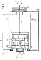
- FIGS. 1 and 2 show two simple alternative embodiments of cable winches 1 with two-stage planetary gears.
- the two-stage planetary gear 10 is arranged in a housing pot 8, which in turn is located in the drum 2, to which it is connected in a torsionally rigid manner.
- the drum 2 is rotatably mounted in the frame 3 of the winch 1.
- An arrow marked “L” indicates the direction of force of a load hanging on the winch drum 2.
- a first drive motor 15 drives a sun gear 43 of a planetary stage 42 via a drive shaft 16, which is therefore referred to below as the drive planetary stage 42.
- the rotational movement of the sun gear 43 is transmitted to the sun gear 23 of a first planetary stage via a common planet web 44 of the planet gears 45, 46 and 47 (not shown).
- the sun gear 23 is connected to the planetary web 44 via a hollow shaft 21.
- the rotational movement of the sun gear 23 is transmitted via the planet gears 25, 26 and the planet gear 27, not shown, to the ring gear 28 of the first planetary stage, which is connected with the housing pot 8 and thus the drum 2 in a torsionally rigid manner.
- the first planetary stage 22, which will be referred to in the following functionally as the output planetary stage 22, thus has planetary gears 25, 26 and 27, which absorb the reaction forces of the drum 2 as a result of their support against the frame 3.
- the ring gear 48 of the drive planetary stage 42 is attached to a shaft 12 which is rotatably mounted relative to the housing pot 8 of the planetary gear 10 and the frame 3 of the cable winch 1 and on which engages a brake 11 which is fixedly connected to the winch frame 3 and serves as a free-fall brake. Due to this arrangement of the free-fall brake 11, comparatively high speeds must be used are braked, but on the other hand, as desired, a proportional reduction in the torque to be absorbed.
- the thermal load can be controlled by using a multi-disc brake 11 flooded with oil. In the exemplary embodiment, the brake 11 is arranged outside the winch frame 2 and is therefore easily accessible in the event of necessary maintenance and repair work.
- a dashed line shows a second drive motor 17 which drives the ring gear 48 of the drive planetary stage 42 via the shaft 12 which now serves as the drive shaft.
- the drive planetary stage 42 now transmits the superimposed rotary movements of both drive motors 15 and 17 to the sun gear 23 of the output planetary stage 22 by means of its planetary web 44.
- FIG. 2 shows an alternative embodiment, which differs from that shown in FIG. 1 only in that instead of the planetary web 44, the ring gear 48 of the drive planetary stage 42 serves as the output web for the output planetary stage 22.
- the planetary web 44 of the drive planetary stage 42 is the non-abrading web (free link), which can be braked with respect to the winch frame 3 by the free-fall brake 11.
- a three-stage planetary gear 10 is used, in which an intermediate planetary stage 32 is driven by the driven planetary web 44 of the drive planetary stage 42 and whose planetary web 34 in turn serves as an output to the output planetary stage 22.
- the abrupt planetary webs 44 and 34 are each connected via hollow shafts 21 and 19 to the sun gears 33 and 23 of the subsequent planetary stages.
- the drive shaft 16 of the drive motor 15 extends through both hollow shafts 19 and 21 to the sun gear 43 of the drive planetary stage 42.
- the free, non-abrasive ring gears 32 and 42 of the intermediate and drive planetary stages 32 and 42 are torsionally rigidly connected to one another and arranged in a common connecting bell 9.
- the connecting bell 9, which can be designed as a tin pot or made from a suitable light metal alloy, is at 19 and 29 relative to the housing pot 8 of the planetary gear 10 and the winch frame 3 is freely rotatable.
- the shaft 12 serves only as a brake shaft on which the free-fall brake 11, which is designed as a multi-disc brake, engages, which in turn is fastened to the winch frame 3.
- the intermediate and drive planetary stages 32 and 42 together form, via their torsionally rigidly connected ring gears 38 and 48, a coupling gear 40 with a rotating housing designed as a connecting bell 9. Only its reaction torque is supplied to the correspondingly small brake 11.
- the second drive motor 17 drives a sun gear 63 of an additional input planetary stage 62 via a drive shaft 18.
- the planetary web 64 of this input planetary stage 62 is torsionally rigidly connected to the ring gear 48 of the drive planetary stage 42.
- the rotary movements of the first and second drive motors 15 and 17 are now brought together and superimposed on the drive planetary stage 42 and driven via their planetary web 44 onto the sun gear 33 of the intermediate planetary stage 32 connected downstream.
- the connecting bell 9 in which the ring gears 38 and 68 of the intermediate and input planetary stages 32 and 62 are arranged so as to be torsionally rigid, is again fastened on the shaft 12 on which the free-fall brake 11 engages.
- the intermediate and input planetary stages 32 and 62 through their torsionally rigid connection together with the drive planetary stage 42, form a superposition coupling gear 41.
- the shaft 12 is designed as a hollow shaft, through which the drive shaft 18 of the second drive motor 17 extends.
- a multi-disc brake 7 and 11 is provided for both the shaft 12 and the drive shaft 18. In operation as a free-fall winch, the winch drum 2 is released by actuating the brake 11. The two holding brakes 6 and 7 remain closed.
- the planetary gear 10 acts as a superposition gear for the two drive motors 15 and 17.
- the cable winch 1 is in this case used as a high-speed Winch operated. At closed brakes 6 and 11, but released brake 7, a fine lift operation of the cable winch 1 can be realized by driving the second drive motor 17 alone, with a corresponding translation of the input planetary stage.
- This exemplary embodiment clearly shows the high versatility of the cable winch due to the modular combination of the functional elements free fall brake 11 and second drive motor 17.
Landscapes
- Engineering & Computer Science (AREA)
- Mechanical Engineering (AREA)
- Retarders (AREA)
- Lubricants (AREA)
- Production Of Liquid Hydrocarbon Mixture For Refining Petroleum (AREA)
Applications Claiming Priority (2)
| Application Number | Priority Date | Filing Date | Title |
|---|---|---|---|
| DE19914134722 DE4134722C3 (de) | 1991-10-21 | 1991-10-21 | Freifallwinde |
| DE4134722 | 1991-10-21 |
Publications (3)
| Publication Number | Publication Date |
|---|---|
| EP0538662A2 true EP0538662A2 (fr) | 1993-04-28 |
| EP0538662A3 EP0538662A3 (fr) | 1994-08-03 |
| EP0538662B1 EP0538662B1 (fr) | 1997-05-28 |
Family
ID=6443099
Family Applications (1)
| Application Number | Title | Priority Date | Filing Date |
|---|---|---|---|
| EP19920116897 Expired - Lifetime EP0538662B1 (fr) | 1991-10-21 | 1992-10-02 | Treuil à chute libre |
Country Status (3)
| Country | Link |
|---|---|
| EP (1) | EP0538662B1 (fr) |
| DE (1) | DE4134722C3 (fr) |
| NO (1) | NO304780B1 (fr) |
Cited By (5)
| Publication number | Priority date | Publication date | Assignee | Title |
|---|---|---|---|---|
| DE10120249C1 (de) * | 2001-04-25 | 2002-10-02 | Lohmann & Stolterfoht Gmbh | Freifallwinde |
| WO2012019921A1 (fr) * | 2010-08-12 | 2012-02-16 | Zollern Gmbh & Co. Kg | Treuil à ensemble régulateur à force centrifuge |
| WO2019048303A1 (fr) * | 2017-09-05 | 2019-03-14 | Liebherr-Components Biberach Gmbh | Treuil à chute libre |
| WO2019048282A1 (fr) * | 2017-09-06 | 2019-03-14 | Liebherr-Components Biberach Gmbh | Treuil à chute libre |
| EP3529195A4 (fr) * | 2016-10-24 | 2020-06-17 | Ingersoll-Rand Industrial U.S., Inc. | Treuil à double capacité faisant appel à deux moteurs et à une seule boîte de vitesses et tambour |
Families Citing this family (9)
| Publication number | Priority date | Publication date | Assignee | Title |
|---|---|---|---|---|
| DE4446443C2 (de) * | 1994-12-23 | 1996-10-02 | Fuerstlich Hohenzollernsche We | Winde mit einer als Freifallbremse verwendbaren Kupplung |
| DE29609536U1 (de) * | 1996-05-30 | 1997-10-30 | Siebenhaar Antriebstechnik GmbH, 34369 Hofgeismar | Zweistufiges Getriebe zum Einbau in eine Freifallwinde |
| CN102328886B (zh) * | 2011-07-20 | 2013-08-21 | 徐州科源液压有限公司 | 卷扬减速机 |
| EP3028983B1 (fr) | 2014-12-05 | 2018-02-07 | Zollern GmbH & Co. KG | Treuil, en particulier treuil à chute libre doté d'un frein de service et d'arrêt |
| DE102014117981B4 (de) | 2014-12-05 | 2020-12-03 | Zollern Gmbh & Co. Kg | Winde mit einer Notabsenkeinrichtung |
| DE102015003980A1 (de) * | 2015-03-26 | 2016-09-29 | Liebherr-Werk Nenzing Gmbh | Verfahren zur Steuerung einer Baumaschine sowie Schürfkübelbagger |
| DE102017116956B4 (de) | 2017-07-26 | 2026-05-07 | Zollern Gmbh & Co. Kg | Winde, insbesondere Freifallwinde mit einer Bremse |
| DE102017223472A1 (de) * | 2017-12-20 | 2019-06-27 | Zf Friedrichshafen Ag | Winden-Schaltgetriebe |
| DE102023115442A1 (de) * | 2023-06-14 | 2024-12-19 | Liebherr-Components Biberach Gmbh | Freifallwinde |
Family Cites Families (11)
| Publication number | Priority date | Publication date | Assignee | Title |
|---|---|---|---|---|
| DE7234056U (de) * | 1972-12-21 | Rheinstahl Ag | Getriebe fur den Antrieb der Hub trommeln von Krananlagen, bei denen der Lasthub und der Leerhub unterschied liehe Geschwindigkeiten aufweisen | |
| FR732213A (fr) * | 1932-02-26 | 1932-09-15 | Prep Ind Combustibles | Treuil de raclage à grande puissance |
| US2891767A (en) * | 1954-12-17 | 1959-06-23 | Euclid Crane & Hoist Company | Hoist with gear reduction |
| US3475991A (en) * | 1967-07-17 | 1969-11-04 | Bowen Tools Inc | Transmission assembly |
| GB1401630A (en) * | 1971-12-02 | 1975-07-16 | Hamworthy Engineering | Winch drive |
| DE2304370A1 (de) * | 1973-01-26 | 1974-08-08 | Mannesmann Meer Ag | Seilwinde mit einem innerhalb ihrer geschlossenen trommel angeordneten planetengetriebe |
| US3850411A (en) * | 1973-06-01 | 1974-11-26 | F Vavilov | Hoisting winch |
| DE7516081U (de) * | 1975-05-21 | 1975-10-02 | Flender A & Co | Trommelwinde |
| CA1129378A (fr) * | 1978-10-06 | 1982-08-10 | Lawrence R. Hock | Mecanisme de commande pour godet de pelle mecanique et engins analogues |
| DE3223632A1 (de) * | 1982-06-22 | 1983-12-22 | Mannesmann AG, 4000 Düsseldorf | Freifallwinde |
| JPH05155589A (ja) * | 1991-12-03 | 1993-06-22 | Hitachi Constr Mach Co Ltd | ウインチ装置 |
-
1991
- 1991-10-21 DE DE19914134722 patent/DE4134722C3/de not_active Expired - Lifetime
-
1992
- 1992-10-02 EP EP19920116897 patent/EP0538662B1/fr not_active Expired - Lifetime
- 1992-10-20 NO NO924053A patent/NO304780B1/no not_active IP Right Cessation
Cited By (9)
| Publication number | Priority date | Publication date | Assignee | Title |
|---|---|---|---|---|
| DE10120249C1 (de) * | 2001-04-25 | 2002-10-02 | Lohmann & Stolterfoht Gmbh | Freifallwinde |
| WO2012019921A1 (fr) * | 2010-08-12 | 2012-02-16 | Zollern Gmbh & Co. Kg | Treuil à ensemble régulateur à force centrifuge |
| EP3529195A4 (fr) * | 2016-10-24 | 2020-06-17 | Ingersoll-Rand Industrial U.S., Inc. | Treuil à double capacité faisant appel à deux moteurs et à une seule boîte de vitesses et tambour |
| WO2019048303A1 (fr) * | 2017-09-05 | 2019-03-14 | Liebherr-Components Biberach Gmbh | Treuil à chute libre |
| US11124396B2 (en) | 2017-09-05 | 2021-09-21 | Liebherr-Components Biberach Gmbh | Free fall winch |
| AU2018328714B2 (en) * | 2017-09-05 | 2023-12-21 | Liebherr-Components Biberach Gmbh | Free fall winch |
| WO2019048282A1 (fr) * | 2017-09-06 | 2019-03-14 | Liebherr-Components Biberach Gmbh | Treuil à chute libre |
| US11535499B2 (en) | 2017-09-06 | 2022-12-27 | Liebherr-Components Biberach Gmbh | Free fall winch |
| AU2018328693B2 (en) * | 2017-09-06 | 2023-12-14 | Liebherr-Components Biberach Gmbh | Free fall winch |
Also Published As
| Publication number | Publication date |
|---|---|
| EP0538662A3 (fr) | 1994-08-03 |
| EP0538662B1 (fr) | 1997-05-28 |
| DE4134722C3 (de) | 1998-02-26 |
| NO924053L (no) | 1993-04-22 |
| DE4134722A1 (de) | 1993-04-22 |
| DE4134722C2 (de) | 1993-12-09 |
| NO924053D0 (no) | 1992-10-20 |
| NO304780B1 (no) | 1999-02-15 |
Similar Documents
| Publication | Publication Date | Title |
|---|---|---|
| EP1259455B1 (fr) | Dispositif de levage | |
| DE69207314T2 (de) | Windebremsvorrichtung | |
| EP0538662B1 (fr) | Treuil à chute libre | |
| DE4206086B4 (de) | Modular aufgebautes Antriebssystem | |
| DE3935570A1 (de) | Planetenrad-uebersetzungsgetriebe fuer ein kraftfahrzeug | |
| DE2802227A1 (de) | Winde | |
| EP3658485A1 (fr) | Treuil à chute libre | |
| DE2940162C2 (de) | Hochlöffelbagger mit einem Löffelvorschubantrieb | |
| DE10348666A1 (de) | Hebewerk | |
| DE3627909C2 (fr) | ||
| DE2929445C2 (de) | Zweigang-Schaltnabe für ein Fahrrad | |
| DE19959999C2 (de) | Hebezeug | |
| DE4321699C1 (de) | Stirnradgetriebe, insbesondere für eine Antriebseinheit eines Flurförderzeugs | |
| EP4095083B1 (fr) | Agencement d'alignement d'une charge soulevée | |
| DE2063695C3 (de) | Antriebsstation für die Hobel und/oder Fördererkette von Hobeln und/oder Förderern o.dgl | |
| DE19717808C2 (de) | Freifallwinde mit einem zweistufigen Getriebe | |
| DE4203877A1 (de) | Antrieb fuer arbeitsgeraete, insbesondere fuer land- und bauwirtschaftlich zu nutzende fahrzeuge | |
| DE3111178C2 (de) | Leistungsregelbarer Antrieb für Werkzeugmaschinen | |
| DE4134742C1 (fr) | ||
| DE3545134A1 (de) | Zweitrommelwinde | |
| DE3513586C1 (de) | Antriebsanordnung für einen Dreh-, Schwenk- und Fahrantrieb eines Fahrzeuges, insbesondere eines Baggers | |
| DE102023115442A1 (de) | Freifallwinde | |
| DE20006712U1 (de) | Windwerk, insbesondere Freifallwinde | |
| DE19616356C2 (de) | Planetenradschaltgetriebe | |
| AT403038B (de) | Kabelkran |
Legal Events
| Date | Code | Title | Description |
|---|---|---|---|
| PUAI | Public reference made under article 153(3) epc to a published international application that has entered the european phase |
Free format text: ORIGINAL CODE: 0009012 |
|
| AK | Designated contracting states |
Kind code of ref document: A2 Designated state(s): GB IT NL SE |
|
| PUAL | Search report despatched |
Free format text: ORIGINAL CODE: 0009013 |
|
| AK | Designated contracting states |
Kind code of ref document: A3 Designated state(s): GB IT NL SE |
|
| 17P | Request for examination filed |
Effective date: 19940824 |
|
| 17Q | First examination report despatched |
Effective date: 19960105 |
|
| GRAG | Despatch of communication of intention to grant |
Free format text: ORIGINAL CODE: EPIDOS AGRA |
|
| GRAH | Despatch of communication of intention to grant a patent |
Free format text: ORIGINAL CODE: EPIDOS IGRA |
|
| GRAH | Despatch of communication of intention to grant a patent |
Free format text: ORIGINAL CODE: EPIDOS IGRA |
|
| GRAA | (expected) grant |
Free format text: ORIGINAL CODE: 0009210 |
|
| AK | Designated contracting states |
Kind code of ref document: B1 Designated state(s): GB IT NL SE |
|
| ITF | It: translation for a ep patent filed | ||
| GBT | Gb: translation of ep patent filed (gb section 77(6)(a)/1977) |
Effective date: 19970612 |
|
| PLBE | No opposition filed within time limit |
Free format text: ORIGINAL CODE: 0009261 |
|
| 26N | No opposition filed | ||
| REG | Reference to a national code |
Ref country code: GB Ref legal event code: IF02 |
|
| PGFP | Annual fee paid to national office [announced via postgrant information from national office to epo] |
Ref country code: NL Payment date: 20101013 Year of fee payment: 19 |
|
| PGFP | Annual fee paid to national office [announced via postgrant information from national office to epo] |
Ref country code: SE Payment date: 20101014 Year of fee payment: 19 Ref country code: GB Payment date: 20101021 Year of fee payment: 19 Ref country code: IT Payment date: 20101026 Year of fee payment: 19 |
|
| REG | Reference to a national code |
Ref country code: NL Ref legal event code: V1 Effective date: 20120501 |
|
| GBPC | Gb: european patent ceased through non-payment of renewal fee |
Effective date: 20111002 |
|
| REG | Reference to a national code |
Ref country code: SE Ref legal event code: EUG |
|
| PG25 | Lapsed in a contracting state [announced via postgrant information from national office to epo] |
Ref country code: NL Free format text: LAPSE BECAUSE OF NON-PAYMENT OF DUE FEES Effective date: 20120501 |
|
| PG25 | Lapsed in a contracting state [announced via postgrant information from national office to epo] |
Ref country code: GB Free format text: LAPSE BECAUSE OF NON-PAYMENT OF DUE FEES Effective date: 20111002 Ref country code: IT Free format text: LAPSE BECAUSE OF NON-PAYMENT OF DUE FEES Effective date: 20111002 |
|
| PG25 | Lapsed in a contracting state [announced via postgrant information from national office to epo] |
Ref country code: SE Free format text: LAPSE BECAUSE OF NON-PAYMENT OF DUE FEES Effective date: 20111003 |