EP0538885B1 - Système de mesure du débit sanguin par ultrasons à effet Doppler - Google Patents
Système de mesure du débit sanguin par ultrasons à effet Doppler Download PDFInfo
- Publication number
- EP0538885B1 EP0538885B1 EP92118201A EP92118201A EP0538885B1 EP 0538885 B1 EP0538885 B1 EP 0538885B1 EP 92118201 A EP92118201 A EP 92118201A EP 92118201 A EP92118201 A EP 92118201A EP 0538885 B1 EP0538885 B1 EP 0538885B1
- Authority
- EP
- European Patent Office
- Prior art keywords
- ultrasonic
- blood flow
- blood
- catheter
- velocity
- Prior art date
- Legal status (The legal status is an assumption and is not a legal conclusion. Google has not performed a legal analysis and makes no representation as to the accuracy of the status listed.)
- Expired - Lifetime
Links
- 230000017531 blood circulation Effects 0.000 title claims description 49
- 238000012544 monitoring process Methods 0.000 title claims description 19
- 210000004369 blood Anatomy 0.000 claims description 44
- 239000008280 blood Substances 0.000 claims description 44
- 210000004204 blood vessel Anatomy 0.000 claims description 30
- 238000005070 sampling Methods 0.000 claims 1
- 238000002604 ultrasonography Methods 0.000 claims 1
- 210000001147 pulmonary artery Anatomy 0.000 description 9
- 238000000691 measurement method Methods 0.000 description 7
- 230000000747 cardiac effect Effects 0.000 description 6
- 230000008859 change Effects 0.000 description 6
- 230000004217 heart function Effects 0.000 description 6
- 210000005245 right atrium Anatomy 0.000 description 6
- 238000000034 method Methods 0.000 description 5
- 230000005540 biological transmission Effects 0.000 description 2
- 238000010276 construction Methods 0.000 description 2
- 201000010099 disease Diseases 0.000 description 2
- 208000037265 diseases, disorders, signs and symptoms Diseases 0.000 description 2
- 238000002592 echocardiography Methods 0.000 description 2
- 230000000694 effects Effects 0.000 description 2
- 230000004044 response Effects 0.000 description 2
- 210000003484 anatomy Anatomy 0.000 description 1
- 210000000601 blood cell Anatomy 0.000 description 1
- 239000002872 contrast media Substances 0.000 description 1
- 239000000498 cooling water Substances 0.000 description 1
- 230000003111 delayed effect Effects 0.000 description 1
- 230000001419 dependent effect Effects 0.000 description 1
- 238000001514 detection method Methods 0.000 description 1
- 238000010586 diagram Methods 0.000 description 1
- 239000000284 extract Substances 0.000 description 1
- 210000003191 femoral vein Anatomy 0.000 description 1
- 239000012530 fluid Substances 0.000 description 1
- 230000006870 function Effects 0.000 description 1
- 238000009434 installation Methods 0.000 description 1
- 210000004731 jugular vein Anatomy 0.000 description 1
- 239000007788 liquid Substances 0.000 description 1
- 238000004519 manufacturing process Methods 0.000 description 1
- 239000000463 material Substances 0.000 description 1
- 210000005241 right ventricle Anatomy 0.000 description 1
- 239000000126 substance Substances 0.000 description 1
- 238000001356 surgical procedure Methods 0.000 description 1
- 230000002792 vascular Effects 0.000 description 1
- 210000003462 vein Anatomy 0.000 description 1
- XLYOFNOQVPJJNP-UHFFFAOYSA-N water Substances O XLYOFNOQVPJJNP-UHFFFAOYSA-N 0.000 description 1
Images



Classifications
-
- A—HUMAN NECESSITIES
- A61—MEDICAL OR VETERINARY SCIENCE; HYGIENE
- A61B—DIAGNOSIS; SURGERY; IDENTIFICATION
- A61B5/00—Measuring for diagnostic purposes; Identification of persons
- A61B5/68—Arrangements of detecting, measuring or recording means, e.g. sensors, in relation to patient
- A61B5/6846—Arrangements of detecting, measuring or recording means, e.g. sensors, in relation to patient specially adapted to be brought in contact with an internal body part, i.e. invasive
- A61B5/6847—Arrangements of detecting, measuring or recording means, e.g. sensors, in relation to patient specially adapted to be brought in contact with an internal body part, i.e. invasive mounted on an invasive device
- A61B5/6852—Catheters
- A61B5/6853—Catheters with a balloon
-
- A—HUMAN NECESSITIES
- A61—MEDICAL OR VETERINARY SCIENCE; HYGIENE
- A61B—DIAGNOSIS; SURGERY; IDENTIFICATION
- A61B5/00—Measuring for diagnostic purposes; Identification of persons
- A61B5/02—Detecting, measuring or recording for evaluating the cardiovascular system, e.g. pulse, heart rate, blood pressure or blood flow
- A61B5/026—Measuring blood flow
- A61B5/0275—Measuring blood flow using tracers, e.g. dye dilution
- A61B5/028—Measuring blood flow using tracers, e.g. dye dilution by thermo-dilution
-
- A—HUMAN NECESSITIES
- A61—MEDICAL OR VETERINARY SCIENCE; HYGIENE
- A61B—DIAGNOSIS; SURGERY; IDENTIFICATION
- A61B5/00—Measuring for diagnostic purposes; Identification of persons
- A61B5/103—Measuring devices for testing the shape, pattern, colour, size or movement of the body or parts thereof, for diagnostic purposes
- A61B5/107—Measuring physical dimensions, e.g. size of the entire body or parts thereof
- A61B5/1076—Measuring physical dimensions, e.g. size of the entire body or parts thereof for measuring dimensions inside body cavities, e.g. using catheters
-
- A—HUMAN NECESSITIES
- A61—MEDICAL OR VETERINARY SCIENCE; HYGIENE
- A61B—DIAGNOSIS; SURGERY; IDENTIFICATION
- A61B8/00—Diagnosis using ultrasonic, sonic or infrasonic waves
- A61B8/06—Measuring blood flow
-
- A—HUMAN NECESSITIES
- A61—MEDICAL OR VETERINARY SCIENCE; HYGIENE
- A61B—DIAGNOSIS; SURGERY; IDENTIFICATION
- A61B8/00—Diagnosis using ultrasonic, sonic or infrasonic waves
- A61B8/12—Diagnosis using ultrasonic, sonic or infrasonic waves in body cavities or body tracts, e.g. by using catheters
-
- A—HUMAN NECESSITIES
- A61—MEDICAL OR VETERINARY SCIENCE; HYGIENE
- A61B—DIAGNOSIS; SURGERY; IDENTIFICATION
- A61B8/00—Diagnosis using ultrasonic, sonic or infrasonic waves
- A61B8/44—Constructional features of the ultrasonic, sonic or infrasonic diagnostic device
- A61B8/4444—Constructional features of the ultrasonic, sonic or infrasonic diagnostic device related to the probe
- A61B8/445—Details of catheter construction
Definitions
- the present invention relates to an ultrasonic Doppler blood flow monitoring system, and more specifically to a blood flow monitoring system such that a catheter provided with ultrasonic transducers or vibrators is inserted into a blood vessel to transmit and receive an ultrasonic wave signal to and from the blood flowing through the blood vessel, in order to measure the velocity of flowing blood on the basis of the ultrasonic Doppler shift signals and further to calculate the amount of flowing blood.
- thermodilution measurement method a catheter is inserted from the vein through the right atrium of the heart to the pulmonary artery; cool water is injected into the right atrium through the catheter; and the cardiac output can be estimated on the basis of the change in temperature in the pulmonary artery.
- This catheter is provided with a balloon at the distal tip thereof. Therefore, when this balloon is expanded, it is possible to smoothly carry the catheter from the right atrium to the capillary portions of the pulmonary artery on the blood flow.
- the above-mentioned catheter is called SWAN-GANZ catheter and is widely used. As far as no vascular contrast medium is injected, the catheter itself can be easily inserted into the blood vessel without involving any risk.
- thermodilution measurement method since cooling water must be injected into the right atrium of the heart, the cardiac output is to be inspected at time intervals of about one hour at the most. As a result, there exists a problem in that it is impossible to monitor the cardiac output continuously for many hours. In other words, in the thermodilution measurement method, there exists a problem in that a sudden change of the condition of a patient under operation cannot be detected immediately and therefore appropriate countermeasures to be taken are delayed. The most important functions required by anesthetists, internists, and cardiac surgeons are to monitor the cardiac functions continuously for many hours. From this standpoint, the thermodilution measurement method is not the one which can satisfy their requirements.
- CARDIOMETORICS Corp. has developed a system called DOPCOM/FLOWCATH (Commodity name) which can monitor cardiac functions continuously.
- a catheter provided with ultrasonic Doppler transducers is incorporated.
- the catheter is inserted into a pulmonary artery, and the ultrasonic Doppler transducers provided on the catheter emit ultrasonic waves into the blood vessel and then receive echoes returned therefrom.
- the inner diameter of the pulmonary artery and the velocity of flowing blood are both measured, in order to calculate the amount of flowing blood, that is, the cardiac output, so that the cardiac functions can be monitored.
- Figs. 1(A) and (B) show the essential portion of a catheter 80 for the monitoring system.
- the catheter 80 is provided with a first ultrasonic transducer (ultrasonic vibrator) 81, a second ultrasonic transducer 82, and a third ultrasonic transducer 83.
- the first ultrasonic transducer 81 is disposed in the catheter 80 so that an ultrasonic wave can be transmitted and received at a predetermined angle with respect to the blood flow direction(V).
- the second and third ultrasonic transducers 82 and 83 are disposed in the catheter 80 facing away from each other so that the ultrasonic waves can be transmitted and received in the radial direction of the catheter 80.
- the velocity of flowing blood is obtained on the basis of only the ultrasonic Doppler signal obtained by an ultrasonic wave transmitted and received in the single direction.
- the velocity component (v ⁇ ) in the transmission and reception direction of the first ultrasonic wave is calculated on the basis of an ultrasonic Doppler shift frequency obtained by the first ultrasonic transducer 81; the calculated velocity component (v ⁇ ) is further corrected on the basis of the angle ( ⁇ ) of incidence of the ultrasonic wave with respect to the blood flow direction (V) to calculate an absolute value (v) of the velocity of flowing blood.
- the second and third ultrasonic transducers 82 and 83 also transmit and receive ultrasonic waves to measure the two radial distances d 1 and d 2 to the wall 91 of the blood vessel.
- the velocity of flowing blood is calculated on the assumption that the orientation of the catheter 80 is in parallel to the blood flow direction (V), and further the amount of flowing blood is calculated on the assumption that the sum of the measured radial distances d 1 and d 2 between each transducer and the blood vessel wall and the distance d ⁇ between the transducers is roughly equal to the blood vessel diameter (D).
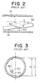
- the orientation of the catheter is not always in parallel to the blood flow direction (V), as depicted in Fig. 2.
- the second and third transducers 82 and 83 cannot necessarily measure the blood vessel diameter accurately.
- the cross-sectional shape of the blood vessel is not always circular.
- the angle ( ⁇ ) of incidence of the ultrasonic wave signal is not constant.
- the velocity (v) of the flowing blood calculated on the basis of the above values inevitably involves an error.
- the catheter 80 is disposed with being offset from the center of the blood vessel, since the measured inner diameter of the blood vessel becomes a value (D1) smaller than the actual inner diameter (D) as depicted in Fig. 3, the cross-sectional area (A) calculated on the basis of the measured inner diameter of the blood vessel inevitably involves another error.
- the amount of flowing blood (Q) calculated as a product of the velocity (v) of the flowing blood and the cross-sectional area (A) of the blood vessel also inevitably includes an error.
- a similar apparatus and a method for measuring volumetric flow of liquid is known from EP 0 363 156 A3.
- This system comprises three ultrasonic transducers, wherein one transducer is provided to measure the velocity of the flowing blood and the other two transducers are disposed in the catheter facing away from each other so that the ultrasonic wave can be transmitted and received in the radial direction of the catheter for measuring the cross-sectional area of the vessel through which the blood is flowing.
- the velocity of flowing blood is calculated on the basis of an ultrasonic Doppler signal obtained by an ultrasonic wave transmitted and received in a single direction.
- the velocity component in the transmission and reception direction of the ultrasonic wave is calculated on the basis of an ultrasonic Doppler-shift frequency obtained by a single ultrasonic transducer.
- the calculated velocity component is further corrected on the basis of the angle of incidence of the ultrasonic wave with respect to the blood flowing direction to calculate an absolute value of the velocity of the flowing blood.
- an ultrasonic Doppler blood flow monitoring system which can measure the velocity of flowing blood continuously without being susceptible to change in the angle of incidence of the ultrasonic wave with respect to the blood flow direction.
- the object is solved by an ultrasonic Doppler blood flow monitoring system with the features of claim 1.
- the ultrasonic Doppler blood flow monitoring system of the present invention since the amount of flowing blood can be measured on the basis of the ultrasonic Doppler shift frequency signals without being susceptible to change in the angle of incidence of each ultrasonic wave with respect to the blood flow direction, even if the catheter is not placed in parallel to the blood flow direction at a bent portion of the blood vessel, it is possible to continuously measure the velocity of flowing blood accurately.
- the two ultrasonic transducers are arranged in such a way that two ultrasonic waves are transmitted and received at two different angles of incidence with respect to the blood flow direction. Further, the two ultrasonic transducers are arranged in such a way that the two ultrasonic waves transmitted from the respective ultrasonic transducer toward the blood flow are perpendicular to each other and not intersected with each other.
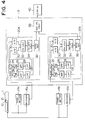
- FIG. 4 shows an entire system configuration.
- a catheter 1 insertable into a blood vessel is provided with two ultrasonic transducers (vibrators) 10 and 12, each of which includes a single transducer element.
- Two transmitters 14a and 14b each for transmitting an ultrasonic transducer exciting signal are connected to the two ultrasonic transducers 10 and 12, respectively.
- each of the ultrasonic transducers 10 and 12 transmits an ultrasonic wave into a blood vessel, respectively and further receives a reflected ultrasonic wave (echo) reflected from a blood cell in a blood of high-speed moving blood flow within the vessel, respectively.
- echo reflected ultrasonic wave
- the frequency of the transmitted ultrasonic wave is different from that of the reflected ultrasonic wave due to the Doppler effect.
- the difference between the frequencies is called Doppler shift.
- the reflected ultrasonic wave with the Doppler shift is converted into an electrical signal in each transducer 10, 12.
- the Doppler shift frequency signals in the transducers 10 and 12 are fed to two receivers 16a and 16b connected to the two transducers 10 and 12, respectively, and further given to two Doppler shift frequency calculation sections 20a and 20b (included in a blood flow velocity measuring section 18) both connected to the receivers 16a and 16b, respectively.
- both the Doppler shift frequency calculation sections 20a and 20b are the same in configuration. Therefore, only the calculation section 20a will be described hereinbelow in further details.
- a quadrature detector 22 detects the received signal to detect only a Doppler shift frequency signal from the reflected ultrasonic wave, and transmits the detected Doppler shift frequency signal to a sample hold circuit 24.
- the detected output is divided into two channels, and processed on the basis of the two reference wave signals having a 90 degree phase difference between the both, for instance as follows:
- the sample hold circuit 24 extracts a Doppler shift frequency signal of any given depth from the output signal of the quadrature detector 22, and transmits the extracted signal to a high-pass filter 26 and then to a low-pass filter 28, in sequence.
- the Doppler detection output signal includes not only a signal reflected from a high-speed moving blood flow but also an unnecessary signal (referred to as clutter) reflected from a low-speed moving substance (e.g. heart wall). Therefore, the signal extracted by the sample hold circuit 24 is passed through the high-pass and low-pass filters 26 and 28 connected in series, to remove the clutter, before being transmitted to two A/D convertors 30 arranged in parallel to each other.
- the A/D convertors 30 convert the two analog signals from each of which clutter is removed, respectively into two digital signals, and transmit the respective digital signals of two channels to a phase calculator 32.
- the phase calculator 32 obtains a phase of the digital signal for each channel, and transmits thus obtained phase signal to a phase difference calculator 34.
- the phase difference calculator 34 calculates a phase difference between the two on the basis of the phases of the respective channels, and thereby calculates the velocity component in the ultrasonic wave transmit/receive direction in every pulse on the basis of the calculated phase difference.
- the phase difference calculator 34 transmits thus obtained data to an average circuit 36.
- the average circuit 36 calculates an average of the velocity components based on the velocity component data which have been obtained in each pulse, and then transmits the calculated results to an absolute value calculator 38.
- the absolute value calculator 38 calculates an absolute value of the velocity of flowing blood on the basis of the average of the velocity components calculated based on the velocity component in each pulse on the basis of the signals obtained by the respective ultrasonic transducers 10 and 12, and outputs the calculated result to the display section 40.
- Fig. 5 shows in detail the distal portion of a catheter 1 not according to the invention.
- the catheter 1 is provided with two ultrasonic transducers 10 and 12 for measuring the velocity of flowing blood.
- the two transducers 10 and 12 are so arranged that two ultrasonic waves are emitted at two different angles of incidence with respect to the blood flow direction, respectively.
- each ultrasonic wave has the same frequency.
- the frequency is preferably to be set from 5MHz to 20MHz. However, it is theoretically possible to constitute the transducers so as to have different frequencies with each other.
- the catheter 1 is provided with a balloon 42 for allowing the catheter 1 to be easily inserted into the pulmonary artery 95 through the right atrium 93 of the heart so as to be carried by the blood flow.
- This balloon 42 is formed of an expansible and contractible material such as rubber and is normally brought into tight contact with the catheter 1.
- a working fluid such as air is injected from the outside into the balloon 42 through a lumen formed in the catheter, the balloon 42 is inflated so as to form a large diameter portion near the distal tip of the catheter 1 as shown in Fig. 5.
- Fig. 6 shows the state where the catheter 1 is fixed at a predetermined position.
- the ultrasonic transducers 10 and 12 provided on the catheter 1 are located in the pulmonary artery 95 so as to transmit ultrasonic waves to the blood flow and further to receive the ultrasonic waves reflected from the blood flow.
- the two ultrasonic transducers 10 and 12 are arranged on the catheter 1 in such a way that the angles ( ⁇ , ⁇ + ⁇ ) of incidence of the two ultrasonic waves transmitted from the respective transducers 10 and 12 with respect to the blood flow direction (V) are different from each other as depicted in Fig. 7(A). Further, the reflected ultrasonic wave signals received by these transducers 10 and 12 are converted into electrical signals, and then fed to the respective receivers 16a and 16b. The two frequencies of these two reflected ultrasonic wave signals are shifted respectively due to the Doppler shift effect in response to the velocity of flowing blood. These frequency shifts are calculated by the two Doppler shift frequency calculation sections 20a and 20b. independently.
- the absolute value calculator 38 calculates the absolute value of the velocity (v) of flowing blood without being susceptible to change in the angle of incidence of the ultrasonic waves.
- the ultrasonic waves are transmitted and received in the two different directions, it is possible to calculate the absolute value of the velocity (v) of flowing blood even when the catheter 1 is placed in a bent portion of the blood vessel and therefore the orientation of the catheter 1 is not in parallel to the direction of the blood flow.
- the arrangement of the two transducers 10 and 12 in the catheter 1 as shown in Fig. 7(A) is sufficient to measure the absolute velocity of flowing blood.
- the absolute value of the velocity of flowing blood can be measured without being susceptible to change in the angle of incidence of the ultrasonic waves transmitted from the ultrasonic transducers with respect to the blood flow direction, it is possible to measure the velocity of flowing blood at a high accuracy, even when the catheter 1 is placed in a bent portion of a blood vessel, and thereby not arranged in parallel to the blood flow direction.
Landscapes
- Health & Medical Sciences (AREA)
- Life Sciences & Earth Sciences (AREA)
- General Health & Medical Sciences (AREA)
- Public Health (AREA)
- Pathology (AREA)
- Engineering & Computer Science (AREA)
- Biomedical Technology (AREA)
- Heart & Thoracic Surgery (AREA)
- Medical Informatics (AREA)
- Molecular Biology (AREA)
- Surgery (AREA)
- Veterinary Medicine (AREA)
- Biophysics (AREA)
- Physics & Mathematics (AREA)
- Animal Behavior & Ethology (AREA)
- Hematology (AREA)
- Nuclear Medicine, Radiotherapy & Molecular Imaging (AREA)
- Radiology & Medical Imaging (AREA)
- Cardiology (AREA)
- Physiology (AREA)
- Dentistry (AREA)
- Oral & Maxillofacial Surgery (AREA)
- Ultra Sonic Daignosis Equipment (AREA)
- Measuring Pulse, Heart Rate, Blood Pressure Or Blood Flow (AREA)
Claims (1)
- Système à ultrasons pour la surveillance du flux sanguin par effet Doppler, comprenant :un cathéter (1) à insérer dans un vaisseau sanguin ;une paire de transducteurs à ultrasons (10, 12) aménagée sur ledit cathéter (1) pour transmettre des ondes ultrasonores vers le flux sanguin, qui s'écoule dans le vaisseau sanguin, dans une certaine direction, et recevoir les ondes ultrasonores qui en sont réfléchies et décalées par les effets Doppler par le flux sanguin ; etdes moyens de calcul (18) servant à calculer la rapidité du flux sanguin en fonction des signaux de fréquence ultrasonores décalés par effet Doppler, obtenus des ondes ultrasonores reçues par lesdits transducteurs à ultrasons (10, 12);
caractérisé en ce quelesdits transducteurs à ultrasons (10, 12) sont prévus pour obtenir des informations nécessaires pour la mesure de la rapidité du flux sanguin s'écoulant dans le vaisseau sanguin, et lesdits transducteurs à ultrasons (10, 12) sont aménagé sur ledit cathéter (1) de telles sortes que lesdites ondes ultrasonores soient transmises en direction de deux points d'échantillonnage espacés dans le flux sanguin, suivant un angle de 90° défini entre ces derniers et sans s'entrecroiser, ce en conséquence de quoi ces ondes ultrasonores sont transmises vers le flux sanguin dans deux directions différentes et selon des angles différents, α et α + 90°, par rapport à la direction du flux sanguin,lesdits moyens de calcul calculant la rapidité du flux sanguin en fonction de l'équation 3 ci-après, en utilisant les signaux de fréquence ultrasonores décalés par effet Doppler, obtenus par ladite paire de transducteurs à ultrasons et représentés par les équations 1 et 2, sans être sensible à la relation angulaire entre la direction d'écoulement du sang et la direction longitudinale du cathéter :- fc :
- Fréquence des ondes ultrasonores transmises
- c :
- Vitesse du son pour un corps vivant
- V :
- Valeur absolue de la rapidité du flux sanguin
- α :
- Angle des ondes ultrasonores transmises par rapport à la direction du flux sanguin.
Priority Applications (1)
| Application Number | Priority Date | Filing Date | Title |
|---|---|---|---|
| EP95107631A EP0670146B1 (fr) | 1991-10-23 | 1992-10-23 | Système Doppler à ultrasons destiné à la surveillance du débit sanguin |
Applications Claiming Priority (4)
| Application Number | Priority Date | Filing Date | Title |
|---|---|---|---|
| JP275132/91 | 1991-10-23 | ||
| JP27513291A JPH05111485A (ja) | 1991-10-23 | 1991-10-23 | 超音波ドプラ血流速度測定装置 |
| JP30196391A JPH0716490B2 (ja) | 1991-11-18 | 1991-11-18 | 超音波ドプラ血流量監視装置 |
| JP301963/91 | 1991-11-18 |
Related Child Applications (2)
| Application Number | Title | Priority Date | Filing Date |
|---|---|---|---|
| EP95107631.4 Division-Into | 1992-10-23 | ||
| EP95107631A Division EP0670146B1 (fr) | 1991-10-23 | 1992-10-23 | Système Doppler à ultrasons destiné à la surveillance du débit sanguin |
Publications (2)
| Publication Number | Publication Date |
|---|---|
| EP0538885A1 EP0538885A1 (fr) | 1993-04-28 |
| EP0538885B1 true EP0538885B1 (fr) | 1999-04-21 |
Family
ID=26551334
Family Applications (2)
| Application Number | Title | Priority Date | Filing Date |
|---|---|---|---|
| EP92118201A Expired - Lifetime EP0538885B1 (fr) | 1991-10-23 | 1992-10-23 | Système de mesure du débit sanguin par ultrasons à effet Doppler |
| EP95107631A Expired - Lifetime EP0670146B1 (fr) | 1991-10-23 | 1992-10-23 | Système Doppler à ultrasons destiné à la surveillance du débit sanguin |
Family Applications After (1)
| Application Number | Title | Priority Date | Filing Date |
|---|---|---|---|
| EP95107631A Expired - Lifetime EP0670146B1 (fr) | 1991-10-23 | 1992-10-23 | Système Doppler à ultrasons destiné à la surveillance du débit sanguin |
Country Status (3)
| Country | Link |
|---|---|
| US (1) | US5339816A (fr) |
| EP (2) | EP0538885B1 (fr) |
| DE (2) | DE69229802T2 (fr) |
Families Citing this family (37)
| Publication number | Priority date | Publication date | Assignee | Title |
|---|---|---|---|---|
| JPH06327672A (ja) * | 1993-05-18 | 1994-11-29 | Toshiba Medical Eng Co Ltd | 超音波ドプラ診断装置 |
| US5433205A (en) * | 1994-04-08 | 1995-07-18 | Visveshwara; Nadarasa | Method of optimizing ventilation perfusion match |
| US5394876A (en) * | 1994-06-30 | 1995-03-07 | Spacelabs Medical, Inc. | Method and apparatus for aiming a doppler flow sensing device |
| EP0814700A1 (fr) * | 1995-03-14 | 1998-01-07 | Vnus Medical Technologies, Inc. | Systeme de controle de l'efficacite de la pompe veineuse et procede correspondant |
| AU1169697A (en) * | 1996-01-05 | 1997-08-01 | Sunlight Ultrasound Technologies Limited | Blood volocity determination |
| US6261233B1 (en) | 1996-01-05 | 2001-07-17 | Sunlight Medical Ltd. | Method and device for a blood velocity determination |
| US5824879A (en) * | 1996-10-04 | 1998-10-20 | Rosemount Inc. | Method of calibrating an ultrasonic flow meter |
| EP0839497A1 (fr) | 1996-11-01 | 1998-05-06 | EndoSonics Corporation | Procédé pour mesurer le débit volumétrique et son profil de vitesse dans un lumen ou dans une cavité d'un corps |
| US6539316B1 (en) | 2000-01-06 | 2003-03-25 | Data Sciences International, Inc. | Phase detector |
| US6435037B1 (en) | 2000-01-06 | 2002-08-20 | Data Sciences International, Inc. | Multiplexed phase detector |
| US6595071B1 (en) | 2000-01-06 | 2003-07-22 | Transoma Medical, Inc. | Estimation of error angle in ultrasound flow measurement |
| AU2001263351A1 (en) * | 2000-05-19 | 2001-12-03 | Echocath, Inc. | Angle-independent doppler system |
| US7008535B1 (en) | 2000-08-04 | 2006-03-07 | Wayne State University | Apparatus for oxygenating wastewater |
| JP4269623B2 (ja) * | 2002-10-07 | 2009-05-27 | 株式会社 東北テクノアーチ | 血流可視化診断装置 |
| US7559894B2 (en) * | 2003-09-18 | 2009-07-14 | New Paradigm Concepts, LLC | Multiparameter whole blood monitor and method |
| JP4441664B2 (ja) * | 2004-07-28 | 2010-03-31 | 株式会社ユネクス | 血管形状測定装置および血流量測定装置 |
| US8323202B2 (en) | 2007-11-16 | 2012-12-04 | Pneumrx, Inc. | Method and system for measuring pulmonary artery circulation information |
| US8593619B2 (en) * | 2008-05-07 | 2013-11-26 | The General Hospital Corporation | System, method and computer-accessible medium for tracking vessel motion during three-dimensional coronary artery microscopy |
| JP2011087710A (ja) * | 2009-10-21 | 2011-05-06 | Toshiba Corp | 超音波診断装置 |
| US9345838B2 (en) | 2012-08-31 | 2016-05-24 | Sanofi-Aventis Deutschland Gmbh | Drug delivery device |
| CN105455848A (zh) * | 2014-09-05 | 2016-04-06 | 鸿富锦精密工业(深圳)有限公司 | 具有自动求救功能的可穿戴式装置和自动求救方法 |
| EP3243432B1 (fr) * | 2015-01-05 | 2022-10-12 | Nipro Corporation | Débitmètre sanguin et dispositif de mesure |
| US12465324B2 (en) | 2015-02-12 | 2025-11-11 | Foundry Innovation & Research 1, Ltd. | Patient fluid management systems and methods employing integrated fluid status sensing |
| WO2018031714A1 (fr) | 2016-08-11 | 2018-02-15 | Foundry Innovation & Research 1, Ltd. | Systèmes et procédés de gestion des fluides chez un patient |
| AU2016219018B2 (en) * | 2015-02-12 | 2020-10-29 | Foundry Innovation & Research 1, Ltd. | Implantable devices and related methods for heart failure monitoring |
| WO2017024051A1 (fr) * | 2015-08-03 | 2017-02-09 | Foundry Innovation & Research 1, Ltd. | Dispositifs et procédés de mesure de dimensions, de pression et de saturation en oxygène de veine cave |
| US11206992B2 (en) | 2016-08-11 | 2021-12-28 | Foundry Innovation & Research 1, Ltd. | Wireless resonant circuit and variable inductance vascular monitoring implants and anchoring structures therefore |
| US11701018B2 (en) | 2016-08-11 | 2023-07-18 | Foundry Innovation & Research 1, Ltd. | Wireless resonant circuit and variable inductance vascular monitoring implants and anchoring structures therefore |
| EP3705031B1 (fr) | 2016-11-29 | 2025-12-10 | Foundry Innovation & Research 1, Ltd. | Implants vasculaires à inductance variable et circuit résonant sans fil permettant de surveiller le système vasculaire |
| EP3629937B1 (fr) | 2017-05-31 | 2026-01-14 | Foundry Innovation & Research 1, Ltd. | Capteur vasculaire ultrasonore implantable |
| WO2018220146A1 (fr) | 2017-05-31 | 2018-12-06 | Foundry Innovation & Research 1, Ltd. | Capteurs implantables pour surveillance vasculaire |
| JP6592164B1 (ja) * | 2018-10-22 | 2019-10-16 | 束原 幸俊 | 血流量プローブ、血流量センサ及び血流量測定器 |
| EP4209178A1 (fr) * | 2022-01-08 | 2023-07-12 | Koninklijke Philips N.V. | Dispositif intraluminal à détection physiologique avec guidage de positionnement et dispositifs, systèmes, et procédés associés |
| WO2023131566A1 (fr) * | 2022-01-08 | 2023-07-13 | Koninklijke Philips N.V. | Dispositif intraluminal de détection physiologique avec guidage de positionnement et dispositifs, systèmes et procédés associés |
| EP4561673A1 (fr) | 2022-07-29 | 2025-06-04 | Foundry Innovation & Research 1, Ltd. | Conducteurs multibrins adaptés à des environnements dynamiques in vivo |
| CN115770064B (zh) * | 2022-11-24 | 2025-02-18 | 苏州晟智医疗科技有限公司 | 血流速度的确定方法及多普勒血流检测装置 |
| CN116269488B (zh) * | 2023-02-23 | 2026-02-10 | 中国科学院苏州生物医学工程技术研究所 | 一种导管及血流检测方法 |
Family Cites Families (13)
| Publication number | Priority date | Publication date | Assignee | Title |
|---|---|---|---|---|
| US4237729A (en) * | 1978-06-02 | 1980-12-09 | Howmedica, Inc. | Doppler flow meter |
| US4259870A (en) * | 1979-02-26 | 1981-04-07 | Howmedica Inc. | Doppler method of measuring flow |
| US4722347A (en) * | 1985-01-15 | 1988-02-02 | Applied Biometrics, Inc. | Apparatus for measuring cardiac output |
| US4856529A (en) * | 1985-05-24 | 1989-08-15 | Cardiometrics, Inc. | Ultrasonic pulmonary artery catheter and method |
| US4733669A (en) * | 1985-05-24 | 1988-03-29 | Cardiometrics, Inc. | Blood flow measurement catheter |
| US5105818A (en) * | 1987-04-10 | 1992-04-21 | Cardiometric, Inc. | Apparatus, system and method for measuring spatial average velocity and/or volumetric flow of blood in a vessel and screw joint for use therewith |
| US4967753A (en) * | 1987-04-10 | 1990-11-06 | Cardiometrics, Inc. | Apparatus, system and method for measuring spatial average velocity and/or volumetric flow of blood in a vessel |
| US4869263A (en) * | 1988-02-04 | 1989-09-26 | Cardiometrics, Inc. | Device and method for measuring volumetric blood flow in a vessel |
| US5121749A (en) * | 1988-10-05 | 1992-06-16 | Cardiometrics, Inc. | Position in dependent volumetric flow measuring apparatus |
| US5078148A (en) * | 1988-10-05 | 1992-01-07 | Cardiometrics, Inc. | Apparatus and method for continuously measuring volumetric blood flow using multiple transducers and catheter for use therewith |
| US4947852A (en) * | 1988-10-05 | 1990-08-14 | Cardiometrics, Inc. | Apparatus and method for continuously measuring volumetric blood flow using multiple transducer and catheter for use therewith |
| US5125137A (en) * | 1990-09-06 | 1992-06-30 | Cardiometrics, Inc. | Method for providing a miniature ultrasound high efficiency transducer assembly |
| US5059851A (en) * | 1990-09-06 | 1991-10-22 | Cardiometrics, Inc. | Miniature ultrasound high efficiency transducer assembly, guidewire using the same and method |
-
1992
- 1992-10-21 US US07/964,549 patent/US5339816A/en not_active Expired - Lifetime
- 1992-10-23 DE DE69229802T patent/DE69229802T2/de not_active Expired - Lifetime
- 1992-10-23 EP EP92118201A patent/EP0538885B1/fr not_active Expired - Lifetime
- 1992-10-23 DE DE69228974T patent/DE69228974T2/de not_active Expired - Lifetime
- 1992-10-23 EP EP95107631A patent/EP0670146B1/fr not_active Expired - Lifetime
Also Published As
| Publication number | Publication date |
|---|---|
| DE69229802D1 (de) | 1999-09-16 |
| US5339816A (en) | 1994-08-23 |
| DE69228974D1 (de) | 1999-05-27 |
| DE69229802T2 (de) | 2000-01-20 |
| EP0670146A1 (fr) | 1995-09-06 |
| EP0538885A1 (fr) | 1993-04-28 |
| EP0670146B1 (fr) | 1999-08-11 |
| DE69228974T2 (de) | 1999-08-26 |
Similar Documents
| Publication | Publication Date | Title |
|---|---|---|
| EP0538885B1 (fr) | Système de mesure du débit sanguin par ultrasons à effet Doppler | |
| US5394876A (en) | Method and apparatus for aiming a doppler flow sensing device | |
| US5840028A (en) | Ultrasonic diagnostic equipment | |
| US4790322A (en) | Ultrasonic type blood flow amount measuring apparatus | |
| US5088498A (en) | Ultrasonic plethysmograph | |
| US4103679A (en) | Method and apparatus for measuring blood flow noninvasively | |
| US5085220A (en) | Doppler flow sensing device and method for its use | |
| US5183046A (en) | Ultrasonic plethysmograph | |
| EP1569560B1 (fr) | Telemetrie ultrasonique destinee a la localisation d'un transducteur d'imagerie | |
| Daigle et al. | Nontraumatic aortic blood flow sensing by use of an ultrasonic esophageal probe | |
| US6770034B2 (en) | Ultrasonic diagnostic apparatus | |
| US20060241459A1 (en) | Automatic signal-optimizing transducer assembly for blood flow measurement | |
| US20160000403A1 (en) | Method and Apparatus for Monitoring Cardiac Output | |
| EP3493744B1 (fr) | Système permettant de déterminer le débit cardiaque | |
| US6726628B2 (en) | Angle-independent doppler system for screening | |
| Wells et al. | Blood velocity patterns in coronary arteries | |
| JP3694357B2 (ja) | 超音波診断装置 | |
| JPH05137725A (ja) | 超音波ドプラ血流量監視装置 | |
| JP3691855B2 (ja) | 超音波診断装置 | |
| CA2077833A1 (fr) | Procede permettant de mesurer la position d'au moins une interface mobile a l'aide d'ultrasons et appareil permettant d'utiliser un tel procede | |
| JPH05168633A (ja) | 超音波組織変位計測装置 | |
| JPH05111485A (ja) | 超音波ドプラ血流速度測定装置 | |
| JP2801450B2 (ja) | 超音波組織変位計測装置 | |
| Patil et al. | A method for localized computation of Pulse Wave Velocity in carotid structure | |
| JPH03244444A (ja) | 超音波ドプラ診断装置 |
Legal Events
| Date | Code | Title | Description |
|---|---|---|---|
| PUAI | Public reference made under article 153(3) epc to a published international application that has entered the european phase |
Free format text: ORIGINAL CODE: 0009012 |
|
| AK | Designated contracting states |
Kind code of ref document: A1 Designated state(s): DE FR GB IT |
|
| 17P | Request for examination filed |
Effective date: 19931022 |
|
| 17Q | First examination report despatched |
Effective date: 19941114 |
|
| GRAG | Despatch of communication of intention to grant |
Free format text: ORIGINAL CODE: EPIDOS AGRA |
|
| GRAG | Despatch of communication of intention to grant |
Free format text: ORIGINAL CODE: EPIDOS AGRA |
|
| GRAH | Despatch of communication of intention to grant a patent |
Free format text: ORIGINAL CODE: EPIDOS IGRA |
|
| GRAH | Despatch of communication of intention to grant a patent |
Free format text: ORIGINAL CODE: EPIDOS IGRA |
|
| GRAA | (expected) grant |
Free format text: ORIGINAL CODE: 0009210 |
|
| AK | Designated contracting states |
Kind code of ref document: B1 Designated state(s): DE FR GB IT |
|
| DX | Miscellaneous (deleted) | ||
| REF | Corresponds to: |
Ref document number: 69228974 Country of ref document: DE Date of ref document: 19990527 |
|
| ET | Fr: translation filed | ||
| PLBE | No opposition filed within time limit |
Free format text: ORIGINAL CODE: 0009261 |
|
| STAA | Information on the status of an ep patent application or granted ep patent |
Free format text: STATUS: NO OPPOSITION FILED WITHIN TIME LIMIT |
|
| 26N | No opposition filed | ||
| REG | Reference to a national code |
Ref country code: GB Ref legal event code: IF02 |
|
| PGFP | Annual fee paid to national office [announced via postgrant information from national office to epo] |
Ref country code: GB Payment date: 20100921 Year of fee payment: 19 |
|
| PGFP | Annual fee paid to national office [announced via postgrant information from national office to epo] |
Ref country code: FR Payment date: 20101027 Year of fee payment: 19 |
|
| PGFP | Annual fee paid to national office [announced via postgrant information from national office to epo] |
Ref country code: DE Payment date: 20101223 Year of fee payment: 19 |
|
| PGFP | Annual fee paid to national office [announced via postgrant information from national office to epo] |
Ref country code: IT Payment date: 20101025 Year of fee payment: 19 |
|
| GBPC | Gb: european patent ceased through non-payment of renewal fee |
Effective date: 20111023 |
|
| REG | Reference to a national code |
Ref country code: FR Ref legal event code: ST Effective date: 20120629 |
|
| PG25 | Lapsed in a contracting state [announced via postgrant information from national office to epo] |
Ref country code: DE Free format text: LAPSE BECAUSE OF NON-PAYMENT OF DUE FEES Effective date: 20120501 |
|
| REG | Reference to a national code |
Ref country code: DE Ref legal event code: R119 Ref document number: 69228974 Country of ref document: DE Effective date: 20120501 |
|
| PG25 | Lapsed in a contracting state [announced via postgrant information from national office to epo] |
Ref country code: FR Free format text: LAPSE BECAUSE OF NON-PAYMENT OF DUE FEES Effective date: 20111102 Ref country code: GB Free format text: LAPSE BECAUSE OF NON-PAYMENT OF DUE FEES Effective date: 20111023 Ref country code: IT Free format text: LAPSE BECAUSE OF NON-PAYMENT OF DUE FEES Effective date: 20111023 |