EP0538954B1 - Installation pour la purification aérobie - Google Patents
Installation pour la purification aérobie Download PDFInfo
- Publication number
- EP0538954B1 EP0538954B1 EP19920203219 EP92203219A EP0538954B1 EP 0538954 B1 EP0538954 B1 EP 0538954B1 EP 19920203219 EP19920203219 EP 19920203219 EP 92203219 A EP92203219 A EP 92203219A EP 0538954 B1 EP0538954 B1 EP 0538954B1
- Authority
- EP
- European Patent Office
- Prior art keywords
- container
- contactor
- wall
- waste water
- water
- Prior art date
- Legal status (The legal status is an assumption and is not a legal conclusion. Google has not performed a legal analysis and makes no representation as to the accuracy of the status listed.)
- Expired - Lifetime
Links
Images


Classifications
-
- C—CHEMISTRY; METALLURGY
- C02—TREATMENT OF WATER, WASTE WATER, SEWAGE, OR SLUDGE
- C02F—TREATMENT OF WATER, WASTE WATER, SEWAGE, OR SLUDGE
- C02F3/00—Biological treatment of water, waste water, or sewage
- C02F3/02—Aerobic processes
- C02F3/08—Aerobic processes using moving contact bodies
- C02F3/082—Rotating biological contactors
-
- Y—GENERAL TAGGING OF NEW TECHNOLOGICAL DEVELOPMENTS; GENERAL TAGGING OF CROSS-SECTIONAL TECHNOLOGIES SPANNING OVER SEVERAL SECTIONS OF THE IPC; TECHNICAL SUBJECTS COVERED BY FORMER USPC CROSS-REFERENCE ART COLLECTIONS [XRACs] AND DIGESTS
- Y02—TECHNOLOGIES OR APPLICATIONS FOR MITIGATION OR ADAPTATION AGAINST CLIMATE CHANGE
- Y02W—CLIMATE CHANGE MITIGATION TECHNOLOGIES RELATED TO WASTEWATER TREATMENT OR WASTE MANAGEMENT
- Y02W10/00—Technologies for wastewater treatment
- Y02W10/10—Biological treatment of water, waste water, or sewage
Definitions
- the invention relates to a device for aerobically purifying industrial and/or household waste water, which device comprises a trough-like container having a semi circular form in cross section and adapted to receive the water for treating, at least two rotatably mounted contactors introduced into the container and having filler elements such as rings arranged loosely therein, feed means for feeding the contaminated water in doses into the container and a sludge collection space for settling the aerobically treated waste water lying behind the container and connected thereto via an overflow, wherein a seal formed by at least one circular wall co-rotating with each contactor is arranged between the contactors to prevent a direct flow from the one contactor to the other.
- Such a device is known from NL-A-8503329, which however take up quite a large amount of space. This volume required for installing such a device is the result of the inaccurate, less controllable water flows from the one treatment contactor to the other, whereby the waste water for treating is not optimally purified. Aerobic treatment of waste water takes place in the rotating contactors which regularly bring the waste water into contact with the ambient air. Because of the short circuit flows a part of the waste water is thereby not sufficiently treated aerobically.
- the invention has for its object to obviate the above stated drawback and provides to this end a device which is distinguished in that means formed by blade-like elements are arranged on the wall for transporting therebetween waste water with increased resistance, and wherein the peripheral edge of at least one wall of said contactor is embodied with an U-shaped flange forming said seal, said outer edge of which connects close-fittingly onto the inner wall of the container or the inner wall of the container is embodied with annular segments along which or between which runs the peripheral edge of said wall forming said seal.
- waste water Due to the seal and the continuous resistance to unimpeded transport from the one contactor to the other of the waste water for treating, not only is the undesirable short circuit flow prevented but the waste water is also fed to the following step in the treatment process such that the total flow through the device is fully controllable.
- the waste water thereby has enough time per step in the treatment process to be effectively aerated whereby the desired aerobic purification can take place.
- the blade-like elements preferably take an elongate form and extend in practically radial or radial sense relative to the rotation shaft and are of a shape such that at each water level they allow passage in limited manner of an equal amount of waste water.
- a return pipe is arranged which extends from the rear side of the trough-like container, as seen in transporting direction of the waste water, to the front side thereof.
- the treated waste water can partially be guided back to the beginning of the aerobic process and/or to any possible preceding processes, which furthers bacteria formation in the process and therefore augments the purification of the waste water.
- a part of the treated water can be guided via a pipe to an anaerobic installation for denitrification.
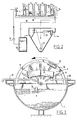
- the device shown in figure 1 consists of a semi-circular container 1 which can either be supported on a frame 2 or be set in a concrete construction, which will not be further elucidated here.
- a drive shaft 3 onto which a number of circular contactors 4 are fixedly attached.
- Each contactor has a front and rear wall 5 whereof at least the front wall can be provided with a peripheral edge in the form of an U-shaped flange 6 opening to the outside.
- annular segments 40 can be arranged in the container along which or between which run the front and terminal walls, see fig. 6.
- the contactor itself is embodied with a shell of perforated plate 7, wherein the contactor is filled with random material 8 for example plastic rings or pieces of tube, which elements serve to enlarge the adhesion surface for bacteria which are necessary for purifying the waste water. The elements are thrown loose into the contactors 4 which prevents excessive growth of bacteria and prevents channel forming.
- random material 8 for example plastic rings or pieces of tube
- Each contactor is provided with one or more air scoops 41 which are incorporated in the shell.
- the air scoop carries air with it during rotation and takes it into the bottom of the container 1.
- the air scoop also carries with it waste water from the tank and empties this over the filler elements.
- the outer periphery of the U-shaped outer edge 6 connect close-fittingly onto the inner wall of the trough-like container 1, also see fig. 3.
- the remaining gap is sealed by the growth of biomass so that in each case a compartment is obtained between the terminal walls of the contactor 4. This avoids short circuit flows along the contactors.
- each contactor 4 are provided with radially oriented slot-like openings 9 which serve to impede a free through-flow of water and which are obtained by pressing out a wall part of the wall 5, also see fig. 4.
- the bulge is such that a blade-like element is created which is disposed protruding only in the front wall to carry into the contactor in each case a part of the quantity of water lying outside the contactor 4.
- each contactor 4 can have both a front and a terminal wall, see fig. 2, instead of a single terminal wall as according to the embodiment in fig. 1.
- the blade-like elements 9 are disposed trailing in the terminal wall.
- the installation is provided at the front with a reservoir 10 which is separated by means of a fixed partition 11 from the part in which the contactors 4 rotate.
- a reservoir 10 which is separated by means of a fixed partition 11 from the part in which the contactors 4 rotate.
- a round disc Arranged in the reservoir on the central shaft is a round disc to which is fixed a number of box-shaped scoop elements 13.
- a collecting tray 17 Arranged in the rear reservoir 10 is a collecting tray 17 which has separate outlets.
- the one outlet of the trough leads to a return pipe 18 which discharges in the front reservoir 10, the other leads to return pipe 19 which can lead to preceding processes.
- An outlet 34 is further arranged which leads to a settling tank 20 to be further elucidated below which is placed close to the trough-like container 1.
- Scoop elements 21 which correspond with the elements 13 and which carry the treated waste water into the trays 17 are also arranged in the rear reservoir portion 10.
- a central drive motor 22 is arranged on the rear end of the shaft 3 to bring about rotation of all contactors 4 including the wall 12 with the scoop elements 13 and the elements 21 close to the rear contactor.
- a settling tank 20 is arranged close to the trough-like container 1 which is shown in fig. 1 as a funnel-shaped container which is partially sunk into the ground.
- the pipe 34 has an outlet opening 25 which debouches into a tubular guide element 26 which is placed in vertical position.
- a sludge pump 27 Arranged in the trough-shaped bottom end of the settling tank 20 is a sludge pump 27 of which the discharge 28 leads to a reservoir 29 with outlet opening 30 for draining the sludge.
- the cleaned water is drained via submerged plate 33 and overflow comb 31 to pipe 32 and can be discharged onto surface water or infiltrated into the ground.
- Rising particles and foam are collected in the tank against the submerged plate 33 by the flow direction. These floating particles are carried into reservoir 29 via gutter 36 and sludge pump 35.
- the above mentioned device operates as follows.
- this part will be filled with the waste water to a maximum level which is equivalent to the top end of the fixed partition 11.
- the shaft 3 and thereby the box-shaped scoop elements 13 By causing the shaft 3 and thereby the box-shaped scoop elements 13 to rotate, a fixed quantity of waste water at a time is scooped out of the front reservoir portion 10 irrespective of the level in reservoir portion 10 and, as a result of the tipping of the scoop shaped elements 13, poured onto partition 11. From there the water runs via the partition 11 to the part of the trough-like space 1 in which the contactors 4 are situated.
- the water will be able to enter the contactor elements 8 due to the blade-like slits 9 in the front wall 5 of the contactor.
- the water is thereby brought into intimate contact with the elements 8 which are themselves lifted out of the quantity of water each time by the rotation of the contactor 4.
- an exceptionally good aeration of the quantity of water in the trough-like container 1 which ensures the good bacteria formation necessary for the aerobic purification of the waste water.
- the waste water is carried in each case over a partition to a new contactor 4 by the continuously dosed transport as a result of the action of the blades 9 and the input of the scoop elements 13.
- a part of the water is scooped out of the section of the trough-like container 1 in which the contactors rotate by the scoop elements 21, wherein the water is discharged via the collecting trays 17.
- a portion of the treated water is returned via the return pipes 18 and 19 to the beginning of the trough-like container 1, namely the front reservoir 10 or to a preceding process. This portion contains a number of bacteria which is necessary to already initiate a bacteria formation there and to activate bacteria already present.
- Another portion of the water is directly discharged to the settling tank 20 where the water with the flocculated sludge particles is carried down into an undisturbed environment via the tube 26, where a separation can take place as a result of the force of gravity.
- the collected sludge is discharged via pump 27 and the captured floating material via pump 35 to the pump reservoir 19.
- the cleaned water can be drained via submerged plate 33 and via the comb 31 and be discharged via pipe 32 onto surface water or infiltrated into the ground.
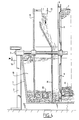
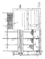
- the waste water that is supplied via feed 16 into the container 1 can be anaerobically treated beforehand in a closed tank 50 which is divided into compartments by partition walls 51 which decrease in height in the flow direction.
- a screen 52 is placed in front of each wall 51 which serves to hold back the floating layer L so that only "clean" water flows to the next compartment.
- a pump 53 guides the pre-treated water to feed pipe 16 for further aerobic treatment.
- Fig. 2 shows that a part of the return pipe 18 or 19 can likewise be branched with a pipe 18' which leads to another anaerobic buffer tank 30 or 50 in fig. 1, which has a pump discharge which leads to the beginning of the trough-like container 1, namely the front reservoir 10.
- a pump 31 provides transport of this anaerobically cleaned water.
- Shown in fig. 6 is an alternative embodiment wherein the same numerals are used for the same components.
- the contactor is provided with a closed partition 43, the outer periphery of which is smaller than that of the terminal walls.
- the water is hereby urged to run along the outer periphery.
- a U-shaped bracket 44 is further arranged between front and terminal wall 5 which serves as stirring member in order to loosen sludge sediment in the bottom of the container 1.
Landscapes
- Life Sciences & Earth Sciences (AREA)
- Engineering & Computer Science (AREA)
- Molecular Biology (AREA)
- Biodiversity & Conservation Biology (AREA)
- Microbiology (AREA)
- Hydrology & Water Resources (AREA)
- Health & Medical Sciences (AREA)
- Environmental & Geological Engineering (AREA)
- Water Supply & Treatment (AREA)
- Chemical & Material Sciences (AREA)
- Organic Chemistry (AREA)
- Biological Treatment Of Waste Water (AREA)
- Purification Treatments By Anaerobic Or Anaerobic And Aerobic Bacteria Or Animals (AREA)
- Fats And Perfumes (AREA)
Claims (7)
- Dispositif de purification aérobie d'eaux usées industrielles et/ou domestiques, lequel dispositif comprend un conteneur en forme d'auge (1) présentant une forme semi-circulaire en coupe transversale, et adapté pour recevoir l'eau à traiter, au moins deux contacteurs (4) montés en vue de leur rotation, introduits dans le conteneur, et comportant des éléments de remplissage (8) tels que des anneaux placés de manière lâche, des moyens d'alimentation (10, 14) pour amener l'eau contaminée par doses dans le conteneur (1) et un espace de collecte des boues (20) pour assurer la décantation de l'eau usée traitée par procédé aérobie derrière le contacteur et connecté à ce dernier via un trop-plein, dans lequel un dispositif de fermeture étanche (6) formé par au moins une paroi circulaire (5) entrant en rotation avec chaque contacteur est placée entre les contacteurs (4) pour éviter un écoulement direct depuis un contacteur vers l'autre, caractérisé en ce que des moyens formés par des éléments en forme de lames (9) sont prévus sur la paroi pour transporter entre eux l'eau usée avec une résistance accrue, et dans lequel le bord périphérique (6) d'au moins une paroi (5) dudit contacteur (4) est représenté par une bride en forme de U formant ladite fermeture étanche, et dont ledit bord extérieur (6) est raccordé, par contact étroit, avec la paroi intérieure du conteneur, ou la paroi intérieure du conteneur (1) est représentée par des segments annulaires (40) le long desquels ou entre lesquels se trouve le bord périphérique de ladite paroi (5) assurant ladite fermeture étanche.
- Dispositif selon la revendication 1, caractérisé en ce que dans chaque cas, deux parois (5) sont prévues par contacteur (4) qui sont formées par les parois terminales du contacteur concerné.
- Dispositif selon la revendication 1, caractérisé en ce que chaque élément en forme de lame (9) est constitué par une partie formée par emboutissage à partir du matériau de la paroi.
- Dispositif selon la revendication 3, caractérisé en ce que chaque élément en forme de lame (9) présente une forme alongée qui s'étend dans le sens radial par rapport à l'arbre de rotation.
- Dispositif selon l'une quelconque des revendications précédentes, caractérisé en ce que chaque contacteur (4) est pourvu d'une cloison (43) dont le bord périphérique extérieur est inférieur à celui (6) de la paroi d'extrémité arrière (5) et respectivement avant du contacteur.
- Dispositif selon l'une quelconque des revendications précédentes, caractérisé en ce que la partie arrière du conteneur en forme d'auge (1) est connectée via un tube de retour (18) à la partie avant du conteneur.
- Dispositif selon la revendication 6, caractérisé en ce que le tube de retour (18) est partiellement raccordé (18') par une dérivation à une installation de purification anaérobie.
Applications Claiming Priority (2)
| Application Number | Priority Date | Filing Date | Title |
|---|---|---|---|
| NL9101776A NL9101776A (nl) | 1991-10-23 | 1991-10-23 | Aerobe zuiveringsinstallatie. |
| NL9101776 | 1991-10-23 |
Publications (2)
| Publication Number | Publication Date |
|---|---|
| EP0538954A1 EP0538954A1 (fr) | 1993-04-28 |
| EP0538954B1 true EP0538954B1 (fr) | 1995-08-02 |
Family
ID=19859842
Family Applications (1)
| Application Number | Title | Priority Date | Filing Date |
|---|---|---|---|
| EP19920203219 Expired - Lifetime EP0538954B1 (fr) | 1991-10-23 | 1992-10-20 | Installation pour la purification aérobie |
Country Status (7)
| Country | Link |
|---|---|
| US (1) | US5290435A (fr) |
| EP (1) | EP0538954B1 (fr) |
| AT (1) | ATE125784T1 (fr) |
| CA (1) | CA2081148A1 (fr) |
| DE (1) | DE69203822T2 (fr) |
| ES (1) | ES2075598T3 (fr) |
| NL (1) | NL9101776A (fr) |
Families Citing this family (14)
| Publication number | Priority date | Publication date | Assignee | Title |
|---|---|---|---|---|
| GB9306226D0 (en) * | 1993-03-25 | 1993-05-19 | Graesser Contractors Ltd | Means for continuous digestion of organic matter |
| DE19520351A1 (de) * | 1995-06-07 | 1996-12-12 | Norddeutsche Seekabelwerke Ag | Füllkörperblock und Verfahren zur Herstellung desselben |
| CA2232464A1 (fr) * | 1997-03-18 | 1998-09-18 | Ken Haggerty | Processus de traitement biologique des eaux usees avec periodes de privation de la biomasse |
| US5840196A (en) * | 1997-06-10 | 1998-11-24 | Laurent; Craig Thomas | Wastewater management product and process |
| US6852227B1 (en) * | 2004-04-29 | 2005-02-08 | Jrj Holdings, Llc | Flow-through media |
| US6949191B1 (en) * | 2004-04-29 | 2005-09-27 | Jrj Holdings, Llc | Packaged wastewater treatment unit |
| WO2005110932A1 (fr) * | 2004-04-29 | 2005-11-24 | Jrj Holdings, Llc | Unite de traitement d'eaux usees integree et supports d'acheminement |
| US7083720B2 (en) * | 2004-05-19 | 2006-08-01 | Gary Miller | Variously configurable rotating biological contactor and prefabricated components therefor |
| EP1717208B1 (fr) * | 2005-04-28 | 2013-06-26 | Grundfos Management A/S | Dispositif de traitement de fluides, en particulier de traitement des eaux usées, avec une pile de disques |
| US7811449B2 (en) * | 2005-10-27 | 2010-10-12 | Waste Stream Technologies, Llc | Flow equalized rotating biological contactor |
| US7452469B1 (en) * | 2007-06-12 | 2008-11-18 | Kyung Jin Kim | Apparatus having rotary activated Baccillus contractor for purifying sewage and wastewater and method using the same |
| US20090050561A1 (en) * | 2007-08-20 | 2009-02-26 | Jon Inman Sattler | System and method for processing wastewater |
| CN108083425B (zh) * | 2017-12-19 | 2021-05-11 | 揭阳市鸿诚五金电子有限公司 | 一种滚筒复合填料支架及方法 |
| CN113023852B (zh) * | 2021-03-29 | 2023-04-28 | 王兴文 | 旋转填料自清洗油泥渣水分离池 |
Citations (1)
| Publication number | Priority date | Publication date | Assignee | Title |
|---|---|---|---|---|
| NL8503329A (nl) * | 1985-12-02 | 1987-07-01 | Pieter Arend Stilkenboom | Water-zuiveringsinrichting en werkwijze. |
Family Cites Families (9)
| Publication number | Priority date | Publication date | Assignee | Title |
|---|---|---|---|---|
| SE328530B (fr) * | 1965-11-04 | 1970-09-14 | H Hartmann | |
| DE1584911C3 (de) * | 1966-10-28 | 1974-09-12 | Hans Dr.-Ing. 8510 Fuerth Hartmann | Verfahren zur biologischen Reinigung von Abwasser mittels Scheibentauchtropfkörpern und Kläranlage zur Durchführung des Verfahrens |
| US3956127A (en) * | 1972-01-26 | 1976-05-11 | European Plastic Machinery Mfg A/S | Apparatus for establishing contact between a liquid and a gas |
| US3817857A (en) * | 1972-09-29 | 1974-06-18 | Autotrol Corp | Treatment of wastewater |
| US3894953A (en) * | 1973-05-29 | 1975-07-15 | Autotrol Corp | Wastewater treatment plant |
| US4200532A (en) * | 1978-06-07 | 1980-04-29 | Ishigaki Kiko Co., Ltd. | Wastewater treatment apparatus |
| US4468326A (en) * | 1982-06-29 | 1984-08-28 | Jorgen Jolner | Process in microbiological purification and a device and materials therefor |
| GB8413751D0 (en) * | 1984-05-30 | 1984-07-04 | Ontario Research Foundation | Biological contact gas scrubber |
| US4729828A (en) * | 1986-12-29 | 1988-03-08 | Gary Miller | Modular rotating biological contactor system |
-
1991
- 1991-10-23 NL NL9101776A patent/NL9101776A/nl not_active Application Discontinuation
-
1992
- 1992-10-20 ES ES92203219T patent/ES2075598T3/es not_active Expired - Lifetime
- 1992-10-20 EP EP19920203219 patent/EP0538954B1/fr not_active Expired - Lifetime
- 1992-10-20 AT AT92203219T patent/ATE125784T1/de not_active IP Right Cessation
- 1992-10-20 DE DE69203822T patent/DE69203822T2/de not_active Expired - Fee Related
- 1992-10-22 US US07/964,614 patent/US5290435A/en not_active Expired - Fee Related
- 1992-10-22 CA CA 2081148 patent/CA2081148A1/fr not_active Abandoned
Patent Citations (1)
| Publication number | Priority date | Publication date | Assignee | Title |
|---|---|---|---|---|
| NL8503329A (nl) * | 1985-12-02 | 1987-07-01 | Pieter Arend Stilkenboom | Water-zuiveringsinrichting en werkwijze. |
Also Published As
| Publication number | Publication date |
|---|---|
| DE69203822T2 (de) | 1995-11-23 |
| US5290435A (en) | 1994-03-01 |
| CA2081148A1 (fr) | 1993-04-24 |
| EP0538954A1 (fr) | 1993-04-28 |
| DE69203822D1 (de) | 1995-09-07 |
| NL9101776A (nl) | 1993-05-17 |
| ATE125784T1 (de) | 1995-08-15 |
| ES2075598T3 (es) | 1995-10-01 |
Similar Documents
| Publication | Publication Date | Title |
|---|---|---|
| EP0538954B1 (fr) | Installation pour la purification aérobie | |
| US4377485A (en) | Apparatus and method for clarification of water using combined flotation and filtration processes | |
| US4655918A (en) | Apparatus for cleaning waste water | |
| EP0641295B1 (fr) | Dispositif d'epuration des eaux usees | |
| CN110683722A (zh) | 一种塑料造粒用的废水净化处理装置及处理工艺 | |
| CN105174631B (zh) | 一种粪便污水固液分离器 | |
| SU1479003A3 (ru) | Устройство дл очистки сточных вод | |
| SK283582B6 (sk) | Reaktor na biologické čistenie odpadových vôd | |
| US4028245A (en) | Arrangement for conversion of foreign matter contained in water | |
| US5948277A (en) | Method for removing floating matter and a removing device | |
| AU685819B2 (en) | High capacity single tank water clarification system | |
| CN214693839U (zh) | 一种污泥浓缩脱水处理设备 | |
| US3485749A (en) | Sewage treatment process and apparatus | |
| US4844800A (en) | Apparatus for waste water treatment | |
| CN217127135U (zh) | 一种带有防堵结构的兰炭废水处理用净化装置 | |
| CN215389937U (zh) | 漂浮杂质收集型螺旋式石料清洗机 | |
| JP3456641B2 (ja) | 生ゴミ類の微生物処理装置 | |
| WO2001000342A1 (fr) | Dispositif de traitement des ordures | |
| CN212707549U (zh) | 一种塑料瓶瓶盖瓶身分离装置 | |
| US3857788A (en) | Sedimentation apparatus with plural sludge discharge feature | |
| CN211896601U (zh) | 一种淤污固液分离一体机 | |
| CN116986775B (zh) | 一种汽车涂装电泳废水预处理装置 | |
| US5665236A (en) | Purification of liquids | |
| Gantz et al. | Equalization and primary treatment | |
| CN218339169U (zh) | 一种污水处理厂用生活垃圾分离装置 |
Legal Events
| Date | Code | Title | Description |
|---|---|---|---|
| PUAI | Public reference made under article 153(3) epc to a published international application that has entered the european phase |
Free format text: ORIGINAL CODE: 0009012 |
|
| AK | Designated contracting states |
Kind code of ref document: A1 Designated state(s): AT BE CH DE ES FR GB IT LI NL |
|
| RAP1 | Party data changed (applicant data changed or rights of an application transferred) |
Owner name: DE VRIES, ARIE CORNELIS |
|
| RIN1 | Information on inventor provided before grant (corrected) |
Inventor name: STILKENBOOM, PIETER AREND |
|
| 17P | Request for examination filed |
Effective date: 19930927 |
|
| 17Q | First examination report despatched |
Effective date: 19940120 |
|
| GRAA | (expected) grant |
Free format text: ORIGINAL CODE: 0009210 |
|
| ITF | It: translation for a ep patent filed | ||
| AK | Designated contracting states |
Kind code of ref document: B1 Designated state(s): AT BE CH DE ES FR GB IT LI NL |
|
| REF | Corresponds to: |
Ref document number: 125784 Country of ref document: AT Date of ref document: 19950815 Kind code of ref document: T |
|
| REF | Corresponds to: |
Ref document number: 69203822 Country of ref document: DE Date of ref document: 19950907 |
|
| REG | Reference to a national code |
Ref country code: ES Ref legal event code: FG2A Ref document number: 2075598 Country of ref document: ES Kind code of ref document: T3 |
|
| ET | Fr: translation filed | ||
| PLBE | No opposition filed within time limit |
Free format text: ORIGINAL CODE: 0009261 |
|
| 26N | No opposition filed | ||
| PGFP | Annual fee paid to national office [announced via postgrant information from national office to epo] |
Ref country code: GB Payment date: 20001002 Year of fee payment: 9 |
|
| PGFP | Annual fee paid to national office [announced via postgrant information from national office to epo] |
Ref country code: CH Payment date: 20010425 Year of fee payment: 9 |
|
| PGFP | Annual fee paid to national office [announced via postgrant information from national office to epo] |
Ref country code: AT Payment date: 20010426 Year of fee payment: 9 Ref country code: BE Payment date: 20010426 Year of fee payment: 9 |
|
| PGFP | Annual fee paid to national office [announced via postgrant information from national office to epo] |
Ref country code: DE Payment date: 20010427 Year of fee payment: 9 Ref country code: FR Payment date: 20010427 Year of fee payment: 9 |
|
| PGFP | Annual fee paid to national office [announced via postgrant information from national office to epo] |
Ref country code: ES Payment date: 20010430 Year of fee payment: 9 Ref country code: NL Payment date: 20010430 Year of fee payment: 9 |
|
| PG25 | Lapsed in a contracting state [announced via postgrant information from national office to epo] |
Ref country code: AT Free format text: LAPSE BECAUSE OF NON-PAYMENT OF DUE FEES Effective date: 20011020 Ref country code: GB Free format text: LAPSE BECAUSE OF NON-PAYMENT OF DUE FEES Effective date: 20011020 |
|
| PG25 | Lapsed in a contracting state [announced via postgrant information from national office to epo] |
Ref country code: ES Free format text: LAPSE BECAUSE OF NON-PAYMENT OF DUE FEES Effective date: 20011021 |
|
| PG25 | Lapsed in a contracting state [announced via postgrant information from national office to epo] |
Ref country code: LI Free format text: LAPSE BECAUSE OF NON-PAYMENT OF DUE FEES Effective date: 20011031 Ref country code: CH Free format text: LAPSE BECAUSE OF NON-PAYMENT OF DUE FEES Effective date: 20011031 Ref country code: BE Free format text: LAPSE BECAUSE OF NON-PAYMENT OF DUE FEES Effective date: 20011031 |
|
| REG | Reference to a national code |
Ref country code: GB Ref legal event code: IF02 |
|
| BERE | Be: lapsed |
Owner name: DE VRIES ARIE CORNELIS Effective date: 20011031 |
|
| PG25 | Lapsed in a contracting state [announced via postgrant information from national office to epo] |
Ref country code: NL Free format text: LAPSE BECAUSE OF NON-PAYMENT OF DUE FEES Effective date: 20020501 |
|
| GBPC | Gb: european patent ceased through non-payment of renewal fee |
Effective date: 20011020 |
|
| REG | Reference to a national code |
Ref country code: CH Ref legal event code: PL |
|
| PG25 | Lapsed in a contracting state [announced via postgrant information from national office to epo] |
Ref country code: FR Free format text: LAPSE BECAUSE OF NON-PAYMENT OF DUE FEES Effective date: 20020628 |
|
| NLV4 | Nl: lapsed or anulled due to non-payment of the annual fee |
Effective date: 20020501 |
|
| PG25 | Lapsed in a contracting state [announced via postgrant information from national office to epo] |
Ref country code: DE Free format text: LAPSE BECAUSE OF NON-PAYMENT OF DUE FEES Effective date: 20020702 |
|
| REG | Reference to a national code |
Ref country code: FR Ref legal event code: ST |
|
| REG | Reference to a national code |
Ref country code: ES Ref legal event code: FD2A Effective date: 20021113 |
|
| PG25 | Lapsed in a contracting state [announced via postgrant information from national office to epo] |
Ref country code: IT Free format text: LAPSE BECAUSE OF NON-PAYMENT OF DUE FEES;WARNING: LAPSES OF ITALIAN PATENTS WITH EFFECTIVE DATE BEFORE 2007 MAY HAVE OCCURRED AT ANY TIME BEFORE 2007. THE CORRECT EFFECTIVE DATE MAY BE DIFFERENT FROM THE ONE RECORDED. Effective date: 20051020 |