EP0539044A2 - Dispositif pour peser des articles - Google Patents
Dispositif pour peser des articles Download PDFInfo
- Publication number
- EP0539044A2 EP0539044A2 EP92308989A EP92308989A EP0539044A2 EP 0539044 A2 EP0539044 A2 EP 0539044A2 EP 92308989 A EP92308989 A EP 92308989A EP 92308989 A EP92308989 A EP 92308989A EP 0539044 A2 EP0539044 A2 EP 0539044A2
- Authority
- EP
- European Patent Office
- Prior art keywords
- weighing apparatus
- article
- base member
- screws
- weighed
- Prior art date
- Legal status (The legal status is an assumption and is not a legal conclusion. Google has not performed a legal analysis and makes no representation as to the accuracy of the status listed.)
- Granted
Links
Images

Classifications
-
- B—PERFORMING OPERATIONS; TRANSPORTING
- B65—CONVEYING; PACKING; STORING; HANDLING THIN OR FILAMENTARY MATERIAL
- B65B—MACHINES, APPARATUS OR DEVICES FOR, OR METHODS OF, PACKAGING ARTICLES OR MATERIALS; UNPACKING
- B65B1/00—Packaging fluent solid material, e.g. powders, granular or loose fibrous material, loose masses of small articles, in individual containers or receptacles, e.g. bags, sacks, boxes, cartons, cans, or jars
- B65B1/30—Devices or methods for controlling or determining the quantity or quality or the material fed or filled
- B65B1/32—Devices or methods for controlling or determining the quantity or quality or the material fed or filled by weighing
Definitions
- This invention relates to weighing apparatus. Particularly, but not exclusively, the invention relates to weighing apparatus to be used in relation to bag filling apparatus.
- a known bag weighing apparatus comprises a platform to provide support for the bottom of the bag as it is being filled.
- the platform is raised to contact the bottom of the bag by means of piston and cylinder devices. With different sites of bag it is necessary to vary the position of the platform.
- a disadvantage of such apparatus is that it is difficult to vary the position of the platform other than by altering the position at which the platform is connected to the piston and cylinder devices or by varying the position of the platform together with its operating piston and cylinder. This can be time consuming. Also, any imbalance in the action of the piston and cylinder devices could result in it being difficult to ensure that the platform rises horizontally and that it is horizontal when it is in contact with the bottom of the bag. In certain situations the base must support also certain components of automatic bag unloading apparatus. Piston and cylinder devices may be unable to support the additional load without expensive upgrading.
- weighing apparatus comprising support means to support the article to be weighed, a base member movable from a first position spaced from the bottom of the article to a second position in contact with the bottom of the article and a screw threaded arrangement to move the base member between the first and second positions.
- the screw threaded arrangement comprises first and second screws mounted on the support means at either side of the article to be weighed.
- the arrangement may also comprise first and second screw receiving members threadably mounted on said screws for relative rotation between said screws and said screw receiving members.
- the screw receiving members may be connected to the base whereby upon said relative rotation, the base is moved between the said first and second positions.
- the screws are fixed tons and said screw receiving members are rotatable on the screws.
- the arrangement may also comprise drive means to rotate the screw receiving members to move the base member between the first and second positions, the base member being connected to the screw receiving members.
- the drive means may comprise a motor mounted on the base member.
- Vibration means may be provided to vibrate the base member when the base member is in the second position.
- the vibration means may comprise at least one motor mounted eccentrically on the base member.
- the vibration means comprises two motors.
- the weighing apparatus may also be provided with stop means to stop the drive means when the base member reaches the second position.
- the stop means are adjustable along the screws so that said second position can be at any desired point above the first position.
- the stop means comprise limit switches.
- the support means may comprise a frame to carry the article to be weighed.
- the frame comprises a ground engaging portion and an article carrying portion.
- the article carrying portion may be connected to the ground engaging portion by load cells.
- the article carrying portion is preferably in the form of a triangle or other three point load bearing structure and one of said load cells may be provided at each apex of the triangle or at each of the three load bearing points.
- the frame may also comprise connecting members to connect the article to be weighed to the triangular portion.
- each connecting member is in the form of a T-shaped member comprising a lower substantially horizontal member and a substantially vertical member extending upwardly from a centre region of the lower member.
- the lower member may be provided with securing means to secure thereto the article to be weighed.
- the securing means may comprise hook means provided on each end of the lower member.
- the frame provides limited movement for the article.
- the weighing apparatus may also comprise filling means to fill the article.
- Gas supply means may also be provided such that, where the article to be weighed is a bag having a liner, the liner can be inflated.
- the gas supply means may comprise a fan or other gas moving apparatus.
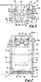
- a weighing apparatus 10 which is suitable for use in filling a large bag (for example, a bag of 1 tonne capacity) with a material.
- the apparatus 10 comprises a support means 12 comprising a frame having a ground engaging portion 17 and an article carrying portion in the form of a triangle 26 and first and second T-shaped members 18,20.
- the T-shaped members 18,20 each comprise a substantially vertical member 22 extending from a centre region of a lower horizontal member 24.
- the T-shaped members 18,20 are removably connected to the triangle 26 by the vertical members 22 via bars 22a.
- the horizontal members 24 are provided with hook means in the form of hooks 28 at each end thereof to which a bag 30 can be attached by means of loops 32.
- the T-shaped members 18,20 are adapted to provide pivotal movement for the bag 30.
- Three shear beam load cells 14,15,16 are each connected to one of the apices of the triangular portion 26, and are mounted on beams 14a,15a and 16a.
- the triangle 26 is attached to feed means 33 comprising a neck support ring 34 to hold the neck 36 of the bag 30, and a nozzle 38 which is disposed in the neck 36 of the bag 30 to facilitate filling of the bag 30.
- the shear beam load cells 14,15,16 are in the form of bars whereby the strain of the weight of the bag 30 on the bars 40,42 is directly proportional to the force applied thereto. In view of this, the weight of the material in the bag 30, can be ascertained by measuring the amount of strain on the bars, as would be appreciated by a person skilled in the art.
- the weighing apparatus 10 also comprises a base member in the form of a platform 44 having sloping sides which is movable up and down between a first position and a second position, the second position being shown in phantom in Fig. 2.
- a base member in the form of a platform 44 having sloping sides which is movable up and down between a first position and a second position, the second position being shown in phantom in Fig. 2.
- First and second screws 46,48 are provided at either side of the support 12.
- the platform 44 is connected to the screws 46,48 by appropriate linkages 50,52 to collars 50a,52a threadably mounted on the screws 46,48.
- the platform 44 is also provided with a drive motor 54 (see Figure 3) to rotate the collars 50a,52a thereby to drive the platform 44 upwards or downwards as desired.
- Eccentrically mounted motors 56,57 are provided to vibrate the platform 44, thereby to ensure that the bag is completely filled with the material.
- Limit switches L are adjustably mounted on or adjacent the screws 48 to detect and signal to the motor 54 when the platform reaches the desired bag supporting position.
- the position of the limit switches can be altered when bags of different sizes are being filled.
- the loops 32 are hooked over the hooks 28 on the horizontal members 24.
- the neck portion 36 is then secured to the neck support ring 34 and the nozzle 38.
- the platform 44 is then raised by rotating the collars 50a,52a in the appropriate directions until the platform 44 contacts the bottom of the bag 30.
- the motors 54,56,57 are provided on the platform 44 and are raised and lowered with the platform 44.
- the motors 56,57 operates to vibrate the platform 44 and thereby the bag, to ensure that the bag is filled.
- the load on the strain gauges increases and thereby, the weight in the bag 30 can be ascertained. It is necessary at intervals to reweigh the bag 30. During such reweighing the platform 44 is lowered.
- the filling is stopped and the bag 30 is removed.
- lowering the platform 44 during filling of the bag 30, enables the bag 30 to stretch to increase its size and also to remove any creases. In this way, the capacity of the bag 30 is increased.
- a fan 60 may be provided for use when the bag 30 has a liner. In use, the fan 60 blow air into the liner of the bag to expand it thereby to facilitate filling of the bag 30.
- the support 12 can be any suitable shape, not necessarily that as shown.
- the T-shaped members and the strain gauges need not be in the position as shown; they could be provided at other places about triangle 26.
- the form for inflating the bag may be replaced by other suitable bag moving apparatus.
- a fan may not be suitable when the bag is inflated by an inert gas, for example, nitrogen.
Landscapes
- Engineering & Computer Science (AREA)
- Quality & Reliability (AREA)
- Mechanical Engineering (AREA)
- Basic Packing Technique (AREA)
- Weight Measurement For Supplying Or Discharging Of Specified Amounts Of Material (AREA)
Applications Claiming Priority (2)
| Application Number | Priority Date | Filing Date | Title |
|---|---|---|---|
| GB919121817A GB9121817D0 (en) | 1991-10-15 | 1991-10-15 | Improvements in or relating to weighing apparatus |
| GB9121817 | 1991-10-15 |
Publications (3)
| Publication Number | Publication Date |
|---|---|
| EP0539044A2 true EP0539044A2 (fr) | 1993-04-28 |
| EP0539044A3 EP0539044A3 (en) | 1993-08-18 |
| EP0539044B1 EP0539044B1 (fr) | 1996-06-26 |
Family
ID=10702925
Family Applications (1)
| Application Number | Title | Priority Date | Filing Date |
|---|---|---|---|
| EP92308989A Expired - Lifetime EP0539044B1 (fr) | 1991-10-15 | 1992-10-01 | Dispositif pour peser des articles |
Country Status (5)
| Country | Link |
|---|---|
| US (1) | US5336853A (fr) |
| EP (1) | EP0539044B1 (fr) |
| JP (1) | JPH05215594A (fr) |
| DE (1) | DE69211807T2 (fr) |
| GB (1) | GB9121817D0 (fr) |
Cited By (2)
| Publication number | Priority date | Publication date | Assignee | Title |
|---|---|---|---|---|
| EP2436602A1 (fr) * | 2010-10-01 | 2012-04-04 | Bühler AG | Dispositif et procédé pour le dosage d'un produit en vrac |
| CN105854730A (zh) * | 2016-06-07 | 2016-08-17 | 淮南市鸿裕工业产品设计有限公司 | 平模制粒机可移动操控的收集装置 |
Families Citing this family (6)
| Publication number | Priority date | Publication date | Assignee | Title |
|---|---|---|---|---|
| DE69214248T2 (de) * | 1991-05-01 | 1997-04-30 | Konishiroku Photo Ind | Automatisches entwicklungsgerät für lichtempfindlichen träger auf silberhalogenidbasis |
| US6119475A (en) * | 1999-03-19 | 2000-09-19 | Spx Corporation | Tank unload apparatus |
| CA2436267C (fr) * | 2003-07-30 | 2010-07-27 | Control And Metering Limited | Table vibrante pour appareil d'ensachage |
| WO2007028251A1 (fr) * | 2005-09-09 | 2007-03-15 | Control And Metering Limited | Appareil d'ensachage modulaire |
| JP6338202B2 (ja) * | 2015-09-28 | 2018-06-06 | 株式会社タツノ | 校正装置 |
| JP6288027B2 (ja) * | 2015-09-28 | 2018-03-07 | 株式会社タツノ | 校正装置及び校正方法 |
Family Cites Families (5)
| Publication number | Priority date | Publication date | Assignee | Title |
|---|---|---|---|---|
| DE918679C (de) * | 1950-09-29 | 1954-09-30 | Michael Siegburg | Packvorrichtung zum Absacken von Mehl, Kleie und aehnlichen Produkten |
| US2981349A (en) * | 1957-04-05 | 1961-04-25 | H L Stoker Company | Shakers for packing material in containers |
| GB2154975B (en) * | 1984-02-29 | 1988-03-16 | Purpose Engineering Limited | Bag filling apparatus |
| GB2178862B (en) * | 1985-08-02 | 1989-08-23 | Purpose Eng Ltd | Improvements in or relating to weighing apparatus |
| US4703782A (en) * | 1985-12-12 | 1987-11-03 | Henkel Sr Ernest H | Method and apparatus for filling bulk bags |
-
1991
- 1991-10-15 GB GB919121817A patent/GB9121817D0/en active Pending
-
1992
- 1992-10-01 EP EP92308989A patent/EP0539044B1/fr not_active Expired - Lifetime
- 1992-10-01 DE DE69211807T patent/DE69211807T2/de not_active Expired - Fee Related
- 1992-10-13 US US07/959,764 patent/US5336853A/en not_active Expired - Lifetime
- 1992-10-15 JP JP4276954A patent/JPH05215594A/ja active Pending
Cited By (4)
| Publication number | Priority date | Publication date | Assignee | Title |
|---|---|---|---|---|
| EP2436602A1 (fr) * | 2010-10-01 | 2012-04-04 | Bühler AG | Dispositif et procédé pour le dosage d'un produit en vrac |
| WO2012042034A1 (fr) * | 2010-10-01 | 2012-04-05 | Bühler AG | Dispositif et procédé de dosage d'un produit en vrac |
| US9266628B2 (en) | 2010-10-01 | 2016-02-23 | Bühler AG | Device and method for metering a bulk material |
| CN105854730A (zh) * | 2016-06-07 | 2016-08-17 | 淮南市鸿裕工业产品设计有限公司 | 平模制粒机可移动操控的收集装置 |
Also Published As
| Publication number | Publication date |
|---|---|
| EP0539044A3 (en) | 1993-08-18 |
| US5336853A (en) | 1994-08-09 |
| JPH05215594A (ja) | 1993-08-24 |
| EP0539044B1 (fr) | 1996-06-26 |
| DE69211807T2 (de) | 1997-01-30 |
| GB9121817D0 (en) | 1991-11-27 |
| DE69211807D1 (de) | 1996-08-01 |
Similar Documents
| Publication | Publication Date | Title |
|---|---|---|
| US4676284A (en) | Bag filling machine with releaseable supporting arms | |
| US5336853A (en) | Weighing apparatus | |
| US5259425A (en) | Method and apparatus for densifying flexible bulk containers | |
| US5400837A (en) | Multi-station filling apparatus and process for filling bulk containers | |
| US5033706A (en) | Rigging frame | |
| US5056571A (en) | Container fill system | |
| US4782865A (en) | Box filling apparatus | |
| KR101728982B1 (ko) | 정미기용 포대 승강장치 | |
| US4718464A (en) | Bag filling apparatus | |
| GB2154975A (en) | Bag filling apparatus | |
| US5354166A (en) | Leaning transfer device | |
| JP2021187673A (ja) | 荷運送作業車における重量ある荷の荷卸し方法及び荷運送作業車 | |
| US11440686B1 (en) | High speed bag filler | |
| AU715386B2 (en) | Self-levelling platform for trolley container | |
| CN210619071U (zh) | 一种多功能吨袋支架 | |
| CN217320940U (zh) | 一种硅料净料包装装置 | |
| CN215338802U (zh) | 集装袋包装袋运输包装件垂直冲击跌落试验机 | |
| KR102519187B1 (ko) | 철근 포장장치 및 철근 포장방법 | |
| JPS5851508B2 (ja) | 物品搬送仲介装置 | |
| KR102199769B1 (ko) | 컨베이어 스케일의 웨이트 승강장치 | |
| CN117923178B (zh) | 一种饲料码垛装置 | |
| CN110436213B (zh) | 一种下沉式翻箱平台 | |
| CN223086429U (zh) | 一种可自动化灌装的茶叶包装设备 | |
| US3512661A (en) | Silo unloader suspension | |
| JP6990788B1 (ja) | 吊り荷の一括設置方法、架台および吊り荷の一括設置システム |
Legal Events
| Date | Code | Title | Description |
|---|---|---|---|
| PUAI | Public reference made under article 153(3) epc to a published international application that has entered the european phase |
Free format text: ORIGINAL CODE: 0009012 |
|
| AK | Designated contracting states |
Kind code of ref document: A2 Designated state(s): DE DK ES FR GB IT NL |
|
| PUAL | Search report despatched |
Free format text: ORIGINAL CODE: 0009013 |
|
| AK | Designated contracting states |
Kind code of ref document: A3 Designated state(s): DE DK ES FR GB IT NL |
|
| 17P | Request for examination filed |
Effective date: 19940112 |
|
| 17Q | First examination report despatched |
Effective date: 19940928 |
|
| GRAH | Despatch of communication of intention to grant a patent |
Free format text: ORIGINAL CODE: EPIDOS IGRA |
|
| GRAH | Despatch of communication of intention to grant a patent |
Free format text: ORIGINAL CODE: EPIDOS IGRA |
|
| GRAA | (expected) grant |
Free format text: ORIGINAL CODE: 0009210 |
|
| AK | Designated contracting states |
Kind code of ref document: B1 Designated state(s): DE DK ES FR GB IT NL |
|
| PG25 | Lapsed in a contracting state [announced via postgrant information from national office to epo] |
Ref country code: IT Free format text: LAPSE BECAUSE OF FAILURE TO SUBMIT A TRANSLATION OF THE DESCRIPTION OR TO PAY THE FEE WITHIN THE PRE;WARNING: LAPSES OF ITALIAN PATENTS WITH EFFECTIVE DATE BEFORE 2007 MAY HAVE OCCURRED AT ANY TIME BEFORE 2007. THE CORRECT EFFECTIVE DATE MAY BE DIFFERENT FROM THE ONE RECORDED.SCRIBED TIME-LIMIT Effective date: 19960626 Ref country code: FR Effective date: 19960626 Ref country code: ES Free format text: THE PATENT HAS BEEN ANNULLED BY A DECISION OF A NATIONAL AUTHORITY Effective date: 19960626 Ref country code: DK Effective date: 19960626 |
|
| REF | Corresponds to: |
Ref document number: 69211807 Country of ref document: DE Date of ref document: 19960801 |
|
| EN | Fr: translation not filed | ||
| PLBE | No opposition filed within time limit |
Free format text: ORIGINAL CODE: 0009261 |
|
| 26N | No opposition filed | ||
| PGFP | Annual fee paid to national office [announced via postgrant information from national office to epo] |
Ref country code: NL Payment date: 19991029 Year of fee payment: 8 Ref country code: DE Payment date: 19991029 Year of fee payment: 8 |
|
| PG25 | Lapsed in a contracting state [announced via postgrant information from national office to epo] |
Ref country code: NL Free format text: LAPSE BECAUSE OF NON-PAYMENT OF DUE FEES Effective date: 20010501 |
|
| NLV4 | Nl: lapsed or anulled due to non-payment of the annual fee |
Effective date: 20010501 |
|
| PG25 | Lapsed in a contracting state [announced via postgrant information from national office to epo] |
Ref country code: DE Free format text: LAPSE BECAUSE OF NON-PAYMENT OF DUE FEES Effective date: 20010703 |
|
| REG | Reference to a national code |
Ref country code: GB Ref legal event code: IF02 |
|
| PGFP | Annual fee paid to national office [announced via postgrant information from national office to epo] |
Ref country code: GB Payment date: 20061002 Year of fee payment: 15 |
|
| GBPC | Gb: european patent ceased through non-payment of renewal fee |
Effective date: 20071001 |
|
| PG25 | Lapsed in a contracting state [announced via postgrant information from national office to epo] |
Ref country code: GB Free format text: LAPSE BECAUSE OF NON-PAYMENT OF DUE FEES Effective date: 20071001 |