EP0539112B1 - Dégivreur pour aile d'avion - Google Patents
Dégivreur pour aile d'avion Download PDFInfo
- Publication number
- EP0539112B1 EP0539112B1 EP19920309453 EP92309453A EP0539112B1 EP 0539112 B1 EP0539112 B1 EP 0539112B1 EP 19920309453 EP19920309453 EP 19920309453 EP 92309453 A EP92309453 A EP 92309453A EP 0539112 B1 EP0539112 B1 EP 0539112B1
- Authority
- EP
- European Patent Office
- Prior art keywords
- icing arrangement
- duct
- elements
- leading edge
- telescopic
- Prior art date
- Legal status (The legal status is an assumption and is not a legal conclusion. Google has not performed a legal analysis and makes no representation as to the accuracy of the status listed.)
- Expired - Lifetime
Links
Images


Classifications
-
- B—PERFORMING OPERATIONS; TRANSPORTING
- B64—AIRCRAFT; AVIATION; COSMONAUTICS
- B64D—EQUIPMENT FOR FITTING IN OR TO AIRCRAFT; FLIGHT SUITS; PARACHUTES; ARRANGEMENT OR MOUNTING OF POWER PLANTS OR PROPULSION TRANSMISSIONS IN AIRCRAFT
- B64D15/00—De-icing or preventing icing on exterior surfaces of aircraft
- B64D15/02—De-icing or preventing icing on exterior surfaces of aircraft by ducted hot gas or liquid
- B64D15/04—Hot gas application
Definitions
- This invention relates to anti-icing arrangements for aircraft wings and in particular to such arrangements including a telescopic air duct to conduct air from a fixed wing or "D-nose" portion to a leading edge slat.
- Such hinged installations tend to have extremely bulky spherical joints which cannot always be used when accommodation space within the wing or slat is at a premium.
- an anti-icing arrangement for an aircraft wing including a fixed wing portion, a leading edge slat movable with respect thereto between a datum cruise position and a deployed high lift position and a telescopic duct having telescopic tubular elements for conducting heated air between the fixed wing portion and the leading edge slat irrespective of the relative positions thereof, the duct being rigidly attached to the fixed wing portion at one end thereof and attached at the other end thereof to the leading edge slat by a universal joint.
- the telescopic duct may have an axis of telescopic movement which may be curved and which generally follows the path of deployment of the leading edge slat.
- Such an arrangement necessitates only a much smaller frontal aperture in the leading edge portion for a slat deployment geometry having a curved path, as vertical movement of a central region of the duct can be substantially eliminated.
- the universal joint may additionally allow limited relative translational movement between the leading edge slat and a said tubular element attached to the joint.
- At least two telescopic tubular elements of the duct may slide with respect to one another upon bearings which permit limited angular deflection of their neutral axes with respect to one another.
- the tubular telescopic duct may comprise at least three said telescopic tubular elements to allow for greater deployment of the leading edge slat.
- the universal joint may comprise a pair of axially overlapping annular elements having a clearance fit therebetween to allow for limited radial relative movement of the two annular elements, a first of said elements having a generally cylindrical surface which is preferably chamfered at one end to ease joint assembly, said surface being slidably engageable by sealing means on the second of said elements to allow translational movement of the two elements relative to one another axially of the joint.
- the sealing means may comprise at least one annular ring and preferably three rings in at least one groove formed in the second annular element.
- the ring or rings is/are preferably of resilient material, for example steel, formed to project from the groove into contact with the cylindrical surface on the first element
- the sealing means may include a groove formed in the second element axially spaced from the at least one groove to receive a further annular ring of resilient deformable material, for example neoprene (Regd. Trade Mark) to form a gas tight seal with the first element.
- a further annular ring of resilient deformable material for example neoprene (Regd. Trade Mark) to form a gas tight seal with the first element.
- the second element may have a surface which is co-extensible with the surface of the first element, slidable with respect thereto, and in which said groove or grooves is/are formed.
- the co-extensive surface of the second element may be relieved in a radial direction at either end to allow only a small radial gap between the two surfaces in a central region of the generally cylindrical surface and yet relative pivotal movement of the first and second elements of the joint about axes in a plane normal to the neutral axis thereof.
- the small radial gap allows limited relative translational movement in a radial direction between the two elements.
- a tubular element of the telescopic duct attached to the universal joint may have a portion cranked with respect to the axis of telescopic movement of the duct.
- the universal joint may include an anti-rotation device to prevent relative axial rotation between the annular elements thereof.
- the tubular element of the duct attached to the fixed wing portion may have the largest cross-sectional area of the tubular elements of the duct whereby the other tubular elements telescope within said element attached to the fixed wing portion.
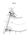
- an aircraft wing comprises a fixed wing portion 1 and a leading edge slat 2.
- the leading edge slat 2 is movable with respect to the fixed wing portion 1 between a datum cruise position, as shown in Figure 1, and a deployed high lift position, as shown in Figure 2.
- a telescopic hot air duct 3 for conducting heated air from the fixed wing portion to the leading edge slat irrespective of the slat position is affixed at one end 4 to the fixed wing portion 1 and at the other end 5 to the leading edge slat 2.
- the telescopic duct has three mutually telescopic tubular elements 6, 7 and 8, the element 8 having a portion 9 cranked with respect to an axis 10 of telescopic movement of the duct (also the neutral axis of elements 6 and 7 of the duct).
- the cranked portion 9 is joined via a universal joint 11 to the leading edge slat.
- the universal joint 11 has an annular first element 12 and an annular second element 13 axially overlapping therewith and slidable axially with respect thereto.
- the first element 12 has a cylindrical internal surface 14 having a chamfer 15 at one end.
- the second element 13 has an external surface 16 co-extensive with the surface 14 on the first element and spaced at a small gap therefrom to allow limited translational movement therebetween in a radial direction.
- Formed in the external surface 16 are grooves 17 and 18.
- the groove 17 receives three steel rings 19, 20 and 21, biased into engagement with the internal surface 14, and the groove 18 receives an annular Neoprene seal 22 therein.
- the steel rings 19, 20, 21 are designed to flex independently of one another and prevent blowby of air under pressure.
- the Neoprene seal 22 is designed to form a gas tight seal between the annular first and second elements 12 and 13. Relative movement between the first and second elements 12 and 13 axially of the joint is allowed by sliding movement between the two surfaces 14 and 16.
- the external surface 16 is relieved at either end thereof to leave gaps 23 and 24 between the surfaces 14 and 16. These gaps allow relative rotation between the first and second annular elements 12 and 13 about axes normal to a neutral axis 25 of the universal joint 11.
- An anti-rotation device for the universal joint 11 comprises a finger 26 engaged in a groove 27 cut in a clamp ring 31.
- the telescopic elements 7 and 8 are mounted on bearings 28, 29, 30, each of which permits a limited degree of relative rotational movement between the elements about axes normal to the neutral axis of the duct.
Landscapes
- Engineering & Computer Science (AREA)
- Aviation & Aerospace Engineering (AREA)
- Joints Allowing Movement (AREA)
- Toys (AREA)
Claims (12)
- Dispositif d'antigivrage pour une aile d'aéronef, comprenant une partie d'aile fixe (1), un bec de bord d'attaque (2) mobile par rapport à celle-ci, entre une position de croisière de référence et une position déployée d'hypersustentation, et un conduit télescopique (3) ayant des éléments tubulaires télescopiques (6, 7, 8) pour acheminer de l'air chauffé entre la partie d'aile fixe (1) et le bec de bord d'attaque (2), indépendamment des positions relatives de ceux-ci, caractérisé en ce que le conduit (3) est rigidement fixé à la partie d'aile fixe (1) par l'une de ses extrémités et en ce qu'il est fixé par son autre extrémité au bec de bord d'attaque (2) par un joint universel (11).
- Dispositif d'antigivrage selon la revendication 1, dans lequel le conduit télescopique a un axe (10) de mouvement télescopique qui suit globalement le trajet de déploiement du bec de bord d'attaque (2).
- Dispositif d'antigivrage selon la revendication 1 ou 2, dans lequel le joint universel (11) permet un mouvement de translation relatif limité entre le bec de bord d'attaque (2) et l'un desdits éléments tubulaires (8), fixé au joint universel (11).
- Dispositif d'antigivrage selon la revendication 1, 2 ou 3, dans lequel au moins deux éléments tubulaires télescopiques (7, 8) du conduit coulissent l'un par rapport à l'autre sur des paliers (28, 29, 30) qui permettent une déviation angulaire limitée de leurs axes neutres (10) l'un par rapport à l'autre.
- Dispositif d'antigivrage selon l'une quelconque des revendications précédentes, dans lequel le joint universel (11) comprend une paire d'éléments à recouvrement axial (12, 13) ayant entre eux un jeu, un premier (12) desdits éléments ayant une surface globalement cylindrique (14) propre à venir en contact par glissement, avec un moyen d'étanchéité sur le second (13) desdits éléments.
- Dispositif d'antigivrage selon la revendication 5, dans lequel le moyen d'étanchéité comprend au moins une bague d'étanchéité (19, 20, 21) dans au moins une rainure (18) formée dans le second élément annulaire (13).
- Dispositif d'antigivrage selon la revendication 6, dans lequel la au moins une bague comprend trois bagues (19, 20, 21).
- Dispositif d'antigivrage selon la revendication 6 ou 7, dans lequel le moyen d'étanchéité comprend une rainure (18) formée dans le second élément annulaire (13) avec un écartement axial par rapport à la au moins une rainure (17), afin de recevoir une autre bague annulaire (22) en une matière élastiquement déformable.
- Dispositif d'antigivrage selon l'une quelconque des revendications 6 à 8, dans lequel le second élément annulaire (13) a une surface (16) co-extensible avec la surface (14) du premier élément (12) et propre à glisser par rapport à celle-ci, et dans laquelle est formée ladite au moins une rainure (18).
- Dispositif d'antigivrage selon la revendication 9, dans lequel la surface co-extensible (16) du second élément annulaire (13) présente une dépouille dans un sens radial à chaque extrémité.
- Dispositif d'antigivrage selon l'une quelconque des revendications 5 à 10, dans lequel le joint universel (11) comprend un dispositif antirotation (26, 27, 31) pour empêcher une rotation axiale relative entre ses éléments annulaires (12, 13).
- Dispositif d'antigivrage selon l'une quelconque des revendications, dans lequel ledit élément tubulaire (6) du conduit (3), qui est fixé à la partie d'aile fixe (1) a la superficie de section transversale la plus grande parmi les éléments tubulaires (6, 7, 8) du conduit (3), les autres éléments tubulaires (7, 8) de celui-ci rentrant de manière télescopique à l'intérieur dudit élément (6) fixé à la partie d'aile fixe (1).
Applications Claiming Priority (2)
| Application Number | Priority Date | Filing Date | Title |
|---|---|---|---|
| GB9122227 | 1991-10-19 | ||
| GB919122227A GB9122227D0 (en) | 1991-10-19 | 1991-10-19 | An anti-icing arrangement for an aircraft wing |
Publications (2)
| Publication Number | Publication Date |
|---|---|
| EP0539112A1 EP0539112A1 (fr) | 1993-04-28 |
| EP0539112B1 true EP0539112B1 (fr) | 1995-01-18 |
Family
ID=10703220
Family Applications (1)
| Application Number | Title | Priority Date | Filing Date |
|---|---|---|---|
| EP19920309453 Expired - Lifetime EP0539112B1 (fr) | 1991-10-19 | 1992-10-16 | Dégivreur pour aile d'avion |
Country Status (4)
| Country | Link |
|---|---|
| EP (1) | EP0539112B1 (fr) |
| DE (1) | DE69201231T2 (fr) |
| ES (1) | ES2068007T3 (fr) |
| GB (1) | GB9122227D0 (fr) |
Cited By (1)
| Publication number | Priority date | Publication date | Assignee | Title |
|---|---|---|---|---|
| US10899430B2 (en) | 2015-02-05 | 2021-01-26 | Airbus Canada Limited Partnership | Apparatus for obstructing air flow through an aperture for a duct in an aircraft wing |
Families Citing this family (2)
| Publication number | Priority date | Publication date | Assignee | Title |
|---|---|---|---|---|
| WO2003013956A1 (fr) * | 2002-03-21 | 2003-02-20 | Nilesh Shriram Narvekar | Mecanisme de deploiement de volets dote de bras pivotants |
| RU2742203C1 (ru) * | 2019-12-26 | 2021-02-03 | Публичное акционерное общество "Научно-производственная корпорация "Иркут" | Противообледенительная система предкрылков самолёта |
Family Cites Families (3)
| Publication number | Priority date | Publication date | Assignee | Title |
|---|---|---|---|---|
| DE746714C (de) * | 1938-07-30 | 1944-12-27 | Einrichtung zur Verhinderung der Eisbildung an dem mit Hilfsfluegeln ausgeruesteten Flugzeugtragwerk | |
| US4603824A (en) * | 1983-08-12 | 1986-08-05 | The Boeing Company | Wing slat anti-ice air duct system with improved slide bearings and air seal |
| US4615499A (en) * | 1983-08-12 | 1986-10-07 | The Boeing Company | Wing slat anti-ice air duct system |
-
1991
- 1991-10-19 GB GB919122227A patent/GB9122227D0/en active Pending
-
1992
- 1992-10-16 DE DE1992601231 patent/DE69201231T2/de not_active Expired - Lifetime
- 1992-10-16 ES ES92309453T patent/ES2068007T3/es not_active Expired - Lifetime
- 1992-10-16 EP EP19920309453 patent/EP0539112B1/fr not_active Expired - Lifetime
Cited By (1)
| Publication number | Priority date | Publication date | Assignee | Title |
|---|---|---|---|---|
| US10899430B2 (en) | 2015-02-05 | 2021-01-26 | Airbus Canada Limited Partnership | Apparatus for obstructing air flow through an aperture for a duct in an aircraft wing |
Also Published As
| Publication number | Publication date |
|---|---|
| DE69201231T2 (de) | 1995-06-22 |
| EP0539112A1 (fr) | 1993-04-28 |
| ES2068007T3 (es) | 1995-04-01 |
| DE69201231D1 (de) | 1995-03-02 |
| GB9122227D0 (en) | 1992-06-17 |
Similar Documents
| Publication | Publication Date | Title |
|---|---|---|
| US6003814A (en) | Double-walled duct assembly for aircraft anti-icing conduit systems | |
| US4643463A (en) | Gimbal joint for piping systems | |
| US4218813A (en) | Method and tool for installing shafts through seals | |
| KR910700079A (ko) | 피하주사기 | |
| GB2192222A (en) | Axial retaining member | |
| GB1603914A (en) | Flexible ball joint | |
| MX9204249A (es) | Articulacion elastica de elevado poder de filtrado y juego axial controlado por topes incorporados, y sus aplicaciones. | |
| SE458796B (sv) | Sammanbyggd taetningsenhet samt foerfarande foer framstaellning av densamma | |
| EP0539112B1 (fr) | Dégivreur pour aile d'avion | |
| US5873544A (en) | Slidable duct assembly for aircraft anti-icing conduit systems | |
| FR2711733B1 (fr) | Inverseur de poussée à portes pour moteur d'avion à réaction équipées d'un volet auxiliaire. | |
| US5642615A (en) | Turbofan engine with a floating pod | |
| GB2226608A (en) | Bearing assembly | |
| US5865400A (en) | Multipiece, slidable duct assembly for aircraft anit-icing conduit systems | |
| CA2276547C (fr) | Dispositif de protection pour ensemble de commande avec double joint de cardan | |
| SE429680B (sv) | Anordning vid brunnar av på varandra staplade rörsektioner innefattande en som fogskydd tjänande tätningsmanschett | |
| US4879534A (en) | Connecting element for waveguides | |
| RU2225664C2 (ru) | Обтекатель | |
| JP4098946B2 (ja) | カルダン式方向づけシステムを備えたターボジェットエンジンの排気ノズル | |
| SE450655B (sv) | Rorforbindning | |
| GB2086534A (en) | Universal joints | |
| EP0899428A1 (fr) | Dispositif de centrage à barres croisées pour volets suiveurs divergents et convergents d'une tuyère d'éjection à géométrie variable | |
| RU2654953C1 (ru) | Обтекатель | |
| CA2281385C (fr) | Mecanisme de guidage pour tuyeres orientables a geometrie variable | |
| US5813768A (en) | Self-aligning bearing structure |
Legal Events
| Date | Code | Title | Description |
|---|---|---|---|
| PUAI | Public reference made under article 153(3) epc to a published international application that has entered the european phase |
Free format text: ORIGINAL CODE: 0009012 |
|
| 17P | Request for examination filed |
Effective date: 19921023 |
|
| AK | Designated contracting states |
Kind code of ref document: A1 Designated state(s): DE ES FR GB IT NL |
|
| 17Q | First examination report despatched |
Effective date: 19940629 |
|
| GRAA | (expected) grant |
Free format text: ORIGINAL CODE: 0009210 |
|
| ITF | It: translation for a ep patent filed | ||
| AK | Designated contracting states |
Kind code of ref document: B1 Designated state(s): DE ES FR GB IT NL |
|
| REF | Corresponds to: |
Ref document number: 69201231 Country of ref document: DE Date of ref document: 19950302 |
|
| ET | Fr: translation filed | ||
| REG | Reference to a national code |
Ref country code: ES Ref legal event code: FG2A Ref document number: 2068007 Country of ref document: ES Kind code of ref document: T3 |
|
| PLBE | No opposition filed within time limit |
Free format text: ORIGINAL CODE: 0009261 |
|
| 26N | No opposition filed | ||
| NLT1 | Nl: modifications of names registered in virtue of documents presented to the patent office pursuant to art. 16 a, paragraph 1 |
Owner name: BAE SYSTEMS PLC |
|
| REG | Reference to a national code |
Ref country code: GB Ref legal event code: IF02 |
|
| REG | Reference to a national code |
Ref country code: GB Ref legal event code: 732E |
|
| REG | Reference to a national code |
Ref country code: FR Ref legal event code: TP |
|
| NLS | Nl: assignments of ep-patents |
Owner name: AIRBUS UK LIMITED |
|
| PGFP | Annual fee paid to national office [announced via postgrant information from national office to epo] |
Ref country code: NL Payment date: 20040921 Year of fee payment: 13 |
|
| PG25 | Lapsed in a contracting state [announced via postgrant information from national office to epo] |
Ref country code: NL Free format text: LAPSE BECAUSE OF NON-PAYMENT OF DUE FEES Effective date: 20060501 |
|
| NLV4 | Nl: lapsed or anulled due to non-payment of the annual fee |
Effective date: 20060501 |
|
| PGFP | Annual fee paid to national office [announced via postgrant information from national office to epo] |
Ref country code: ES Payment date: 20091028 Year of fee payment: 18 |
|
| PGFP | Annual fee paid to national office [announced via postgrant information from national office to epo] |
Ref country code: IT Payment date: 20091029 Year of fee payment: 18 |
|
| PGFP | Annual fee paid to national office [announced via postgrant information from national office to epo] |
Ref country code: DE Payment date: 20101022 Year of fee payment: 19 |
|
| PGFP | Annual fee paid to national office [announced via postgrant information from national office to epo] |
Ref country code: GB Payment date: 20101021 Year of fee payment: 19 |
|
| REG | Reference to a national code |
Ref country code: ES Ref legal event code: FD2A Effective date: 20111118 |
|
| REG | Reference to a national code |
Ref country code: DE Ref legal event code: R082 Ref document number: 69201231 Country of ref document: DE Representative=s name: G. KOCH UND KOLLEGEN, DE |
|
| PG25 | Lapsed in a contracting state [announced via postgrant information from national office to epo] |
Ref country code: IT Free format text: LAPSE BECAUSE OF NON-PAYMENT OF DUE FEES Effective date: 20101016 |
|
| REG | Reference to a national code |
Ref country code: DE Ref legal event code: R082 Ref document number: 69201231 Country of ref document: DE Representative=s name: G. KOCH UND KOLLEGEN, DE Effective date: 20111207 Ref country code: DE Ref legal event code: R081 Ref document number: 69201231 Country of ref document: DE Owner name: AIRBUS OPERATIONS LIMITED, FILTON, GB Free format text: FORMER OWNER: AIRBUS UK LTD., FILTON, BRISTOL, GB Effective date: 20111207 Ref country code: DE Ref legal event code: R081 Ref document number: 69201231 Country of ref document: DE Owner name: AIRBUS OPERATIONS LIMITED, GB Free format text: FORMER OWNER: AIRBUS UK LTD., FILTON, GB Effective date: 20111207 |
|
| PG25 | Lapsed in a contracting state [announced via postgrant information from national office to epo] |
Ref country code: ES Free format text: LAPSE BECAUSE OF NON-PAYMENT OF DUE FEES Effective date: 20101017 |
|
| PGFP | Annual fee paid to national office [announced via postgrant information from national office to epo] |
Ref country code: FR Payment date: 20111103 Year of fee payment: 20 |
|
| REG | Reference to a national code |
Ref country code: DE Ref legal event code: R071 Ref document number: 69201231 Country of ref document: DE |
|
| REG | Reference to a national code |
Ref country code: DE Ref legal event code: R071 Ref document number: 69201231 Country of ref document: DE |
|
| REG | Reference to a national code |
Ref country code: GB Ref legal event code: PE20 Expiry date: 20121015 |
|
| PG25 | Lapsed in a contracting state [announced via postgrant information from national office to epo] |
Ref country code: GB Free format text: LAPSE BECAUSE OF EXPIRATION OF PROTECTION Effective date: 20121015 |