EP0539148A2 - Biologisch implantierbarer Miniaturkabelzusammenbau - Google Patents
Biologisch implantierbarer Miniaturkabelzusammenbau Download PDFInfo
- Publication number
- EP0539148A2 EP0539148A2 EP92309556A EP92309556A EP0539148A2 EP 0539148 A2 EP0539148 A2 EP 0539148A2 EP 92309556 A EP92309556 A EP 92309556A EP 92309556 A EP92309556 A EP 92309556A EP 0539148 A2 EP0539148 A2 EP 0539148A2
- Authority
- EP
- European Patent Office
- Prior art keywords
- conductors
- cable
- insulating material
- layer
- miniature
- Prior art date
- Legal status (The legal status is an assumption and is not a legal conclusion. Google has not performed a legal analysis and makes no representation as to the accuracy of the status listed.)
- Withdrawn
Links
Images




Classifications
-
- H—ELECTRICITY
- H01—ELECTRIC ELEMENTS
- H01R—ELECTRICALLY-CONDUCTIVE CONNECTIONS; STRUCTURAL ASSOCIATIONS OF A PLURALITY OF MUTUALLY-INSULATED ELECTRICAL CONNECTING ELEMENTS; COUPLING DEVICES; CURRENT COLLECTORS
- H01R43/00—Apparatus or processes specially adapted for manufacturing, assembling, maintaining, or repairing of line connectors or current collectors or for joining electric conductors
- H01R43/20—Apparatus or processes specially adapted for manufacturing, assembling, maintaining, or repairing of line connectors or current collectors or for joining electric conductors for assembling or disassembling contact members with insulating base, case or sleeve
- H01R43/24—Assembling by moulding on contact members
-
- A—HUMAN NECESSITIES
- A61—MEDICAL OR VETERINARY SCIENCE; HYGIENE
- A61F—FILTERS IMPLANTABLE INTO BLOOD VESSELS; PROSTHESES; DEVICES PROVIDING PATENCY TO, OR PREVENTING COLLAPSING OF, TUBULAR STRUCTURES OF THE BODY, e.g. STENTS; ORTHOPAEDIC, NURSING OR CONTRACEPTIVE DEVICES; FOMENTATION; TREATMENT OR PROTECTION OF EYES OR EARS; BANDAGES, DRESSINGS OR ABSORBENT PADS; FIRST-AID KITS
- A61F11/00—Methods or devices for treatment of the ears or hearing sense; Non-electric hearing aids; Methods or devices for enabling ear patients to achieve auditory perception through physiological senses other than hearing sense; Protective devices for the ears, carried on the body or in the hand
- A61F11/04—Methods or devices for enabling ear patients to achieve auditory perception through physiological senses other than hearing sense, e.g. through the touch sense
-
- A—HUMAN NECESSITIES
- A61—MEDICAL OR VETERINARY SCIENCE; HYGIENE
- A61N—ELECTROTHERAPY; MAGNETOTHERAPY; RADIATION THERAPY; ULTRASOUND THERAPY
- A61N1/00—Electrotherapy; Circuits therefor
- A61N1/02—Details
- A61N1/04—Electrodes
- A61N1/05—Electrodes for implantation or insertion into the body, e.g. heart electrode
- A61N1/0551—Spinal or peripheral nerve electrodes
-
- H—ELECTRICITY
- H01—ELECTRIC ELEMENTS
- H01R—ELECTRICALLY-CONDUCTIVE CONNECTIONS; STRUCTURAL ASSOCIATIONS OF A PLURALITY OF MUTUALLY-INSULATED ELECTRICAL CONNECTING ELEMENTS; COUPLING DEVICES; CURRENT COLLECTORS
- H01R13/00—Details of coupling devices of the kinds covered by groups H01R12/70 or H01R24/00 - H01R33/00
- H01R13/46—Bases; Cases
- H01R13/50—Bases; Cases formed as an integral body
-
- A—HUMAN NECESSITIES
- A61—MEDICAL OR VETERINARY SCIENCE; HYGIENE
- A61B—DIAGNOSIS; SURGERY; IDENTIFICATION
- A61B18/00—Surgical instruments, devices or methods for transferring non-mechanical forms of energy to or from the body
- A61B2018/00053—Mechanical features of the instrument of device
- A61B2018/00107—Coatings on the energy applicator
-
- A—HUMAN NECESSITIES
- A61—MEDICAL OR VETERINARY SCIENCE; HYGIENE
- A61N—ELECTROTHERAPY; MAGNETOTHERAPY; RADIATION THERAPY; ULTRASOUND THERAPY
- A61N1/00—Electrotherapy; Circuits therefor
- A61N1/02—Details
- A61N1/04—Electrodes
- A61N1/05—Electrodes for implantation or insertion into the body, e.g. heart electrode
- A61N1/0526—Head electrodes
- A61N1/0541—Cochlear electrodes
-
- H—ELECTRICITY
- H01—ELECTRIC ELEMENTS
- H01B—CABLES; CONDUCTORS; INSULATORS; SELECTION OF MATERIALS FOR THEIR CONDUCTIVE, INSULATING OR DIELECTRIC PROPERTIES
- H01B7/00—Insulated conductors or cables characterised by their form
- H01B7/02—Disposition of insulation
- H01B7/0208—Cables with several layers of insulating material
-
- H—ELECTRICITY
- H01—ELECTRIC ELEMENTS
- H01B—CABLES; CONDUCTORS; INSULATORS; SELECTION OF MATERIALS FOR THEIR CONDUCTIVE, INSULATING OR DIELECTRIC PROPERTIES
- H01B7/00—Insulated conductors or cables characterised by their form
- H01B7/08—Flat or ribbon cables
- H01B7/0892—Flat or ribbon cables incorporated in a cable of non-flat configuration
-
- H—ELECTRICITY
- H04—ELECTRIC COMMUNICATION TECHNIQUE
- H04R—LOUDSPEAKERS, MICROPHONES, GRAMOPHONE PICK-UPS OR LIKE ACOUSTIC ELECTROMECHANICAL TRANSDUCERS; ELECTRIC HEARING AIDS; PUBLIC ADDRESS SYSTEMS
- H04R2225/00—Details of deaf aids covered by H04R25/00, not provided for in any of its subgroups
- H04R2225/67—Implantable hearing aids or parts thereof not covered by H04R25/606
-
- Y—GENERAL TAGGING OF NEW TECHNOLOGICAL DEVELOPMENTS; GENERAL TAGGING OF CROSS-SECTIONAL TECHNOLOGIES SPANNING OVER SEVERAL SECTIONS OF THE IPC; TECHNICAL SUBJECTS COVERED BY FORMER USPC CROSS-REFERENCE ART COLLECTIONS [XRACs] AND DIGESTS
- Y10—TECHNICAL SUBJECTS COVERED BY FORMER USPC
- Y10T—TECHNICAL SUBJECTS COVERED BY FORMER US CLASSIFICATION
- Y10T29/00—Metal working
- Y10T29/49—Method of mechanical manufacture
- Y10T29/49002—Electrical device making
- Y10T29/49117—Conductor or circuit manufacturing
- Y10T29/49169—Assembling electrical component directly to terminal or elongated conductor
- Y10T29/49171—Assembling electrical component directly to terminal or elongated conductor with encapsulating
-
- Y—GENERAL TAGGING OF NEW TECHNOLOGICAL DEVELOPMENTS; GENERAL TAGGING OF CROSS-SECTIONAL TECHNOLOGIES SPANNING OVER SEVERAL SECTIONS OF THE IPC; TECHNICAL SUBJECTS COVERED BY FORMER USPC CROSS-REFERENCE ART COLLECTIONS [XRACs] AND DIGESTS
- Y10—TECHNICAL SUBJECTS COVERED BY FORMER USPC
- Y10T—TECHNICAL SUBJECTS COVERED BY FORMER US CLASSIFICATION
- Y10T29/00—Metal working
- Y10T29/49—Method of mechanical manufacture
- Y10T29/49002—Electrical device making
- Y10T29/49117—Conductor or circuit manufacturing
- Y10T29/49194—Assembling elongated conductors, e.g., splicing, etc.
- Y10T29/49201—Assembling elongated conductors, e.g., splicing, etc. with overlapping orienting
Definitions
- the present invention relates to miniature electrically insulated multi-conductor electrical cables, particularly those which may be implanted in living persons, and methods for making such cables.
- Many miniaturized electrical sensors and control devices may conceivably be implanted in human bodies or may be used in robotic devices. Such sensors and other devices may require reliable transmission of electrical signals, yet may have extremely small current requirements. In many cases flexibility of the conductors is highly desired. For example, electrical signals must be transmitted between an implanted biomedical sensor and an electronically controlled device such as a drug delivery device implanted in a separate location. It may also be desirable to provide electrical stimulation to, or to receive signals from, several separate neurons of the human nervous system, at sites spaced as closely as 100 microns from one another. For example, extremely small biologically compatible cochlear implant devices have been designed which utilize multi-electrode arrays to selectively stimulate portions of the basilar membrane to induce hearing in compromised individuals. It may also be desired to provide functional electrical stimulation by surface electrodes or implanted electrodes to mobilize paraplegics. The smaller and more flexible the cable implanted, the less it is likely to be an irritant to the surrounding tissue.
- Haley et al. U.S. Patent No. 4,819,329 discloses making a cable by holding the terminal portions of individual conductors in a fixture, with the ends of the wires stripped of their normal insulating coating to facilitate connection of the wires to printed circuits or the like. The middle portions of the wires can then be insulated and may be twisted together as a cable.
- U.S. Patent No. 4,964,414 discloses an electrode for implantation. Fine stainless steel wires of less than 25 micron diameter are twisted to- getherand coated with a resin which retains the wires and allows them to be implanted.
- U.S. Patent No. 3,751,801 discloses a miniature ribbon cable whose insulation is removed from end portions of the conductor wires. Alternate wires are bent in opposite directions to form two rows for soldering to a terminal, at a pitch established by the ribbon cable.
- U.S. Patent No. 4,840,186 discloses a lead in which multifilament conductors coated with insulation are embedded in a tube wall in a helical arrangement, but the lead so produced is much larger and would be less flexible than desired for certain cable implantations.
- Compte U.S. Patent No. 4,640,983 discloses an electrical conductor intended for implantation into humans, in which multifilament conductors are provided in spiral form and sheathed in a biologically compatible material.
- the conductor disclosed is much larger than the desired implantable cable with which the present invention is concerned.
- a multi-conductor electrical cable of extremely small size which can be implanted in a living body without causing continuing irritation, and which is flexible, durable, electrically insulated, and capable of readily being connected electrically to extremely closely spaced terminals.
- the present invention provides a miniature cable and a method for preparing such a cable to answer the aforementioned need for a miniature multi-conductor electrical cable which is implantable in humans, durable, and small and flexible enough not to be an irritant, and which may readily be connected to closely-spaced terminals of electrical circuits.
- a miniature multi-conductor electrical cable in which each of a pluralityoffine wires of a suitably flexible material such as gold or a platinum-iridium alloy is coated with an insulating material.
- a thin layer of a resin such as a polyimide covered by a second coating of polyesterimide insulating material is very effective as an insulating dielectric system, without greatly increasing the force required to bend the cable.
- a single layer of a polymeric resin such as a polytetrafluoroethylene material (PTFE), perfluorinated ethylenepropylene copolymer (FEP), perfluorinated ethylene-vinyl alkoxy ether copolymer (PFA), silicone, or polyurethane may be used as an insulating coating for individual conductors.
- PTFE polytetrafluoroethylene material
- FEP perfluorinated ethylenepropylene copolymer
- PFA perfluorinated ethylene-vinyl alkoxy ether copolymer
- silicone silicone
- coated wires of the cable according to the present invention are held together, either by being stranded together, as in a seven-conductor helical stranding, or by an additional coating of an insulating material at least partially surrounding each conductor and interconnecting each conductor with an adjacent conductor along at least an intermediate portion of the length of the conductors.
- the conductors may be held together by such an additional coating either as a ribbon-like arrangement of parallel conductors, or in a circular configuration as either a solid-core strand or a hollow strand defining a central lumen between the interconnected helically arranged conductors.
- the individual conductors for such a cable may be prepared, for example, by solution-coating, in the case of the polyimide and polyesterimide insulation materials, or by dispersion coating of an emulsion of a suitable fluorocarbon polymer onto each of the conductors to provide a continuous insulating coating on each conductor.
- the ends of a cable according to the present invention may be prepared for connection to terminals of an electrical circuit by the selective removal of one or more of the layers of insulating material, preferably without damaging a primary layer of material insulating each individual conductor, as required to allow the individual conductors to be moved separately to provide a required pitch between them, after which they are formed into a ribbonized terminal portion of the cable.
- the terminal portions of the separated individual conductor wires are encapsulated in a mechanically supportive insulating material with the conductors at the pitch required for connection of the cable.
- the encapsulating material is then trimmed, and any remaining insulating material coatings are removed from a selected portion of each conductor to expose the metal surface of the conductor for termination.
- One preferred manner of such removal of material is the use of a computer-controlled laser.
- a fixture in which the individual conductors are held parallel with one another at the desired spacing or pitch, while a ribbonizing fixing resin material is cast around the conductors to encapsulate and stabilize them at the correct pitch.
- a preferred ribbonizing, fixing resin is a UV curable silicone resin.
- a cable which is one embodiment of the present invention includes an intermediate portion of the cable including several closely adjacent electrical conductors and a ribbonized terminal portion adjacent at last one end of the cable, including a transition portion in which the conductors diverge from one another and merge into a connector portion in which the several conductors are held at a predetermined spacing, or pitch, with respect to each other.
- the conductors are preferably encapsulated and thus held in a ribbonized form, but with a respective small length of each of the conductors exposed, free of insulating material, as an electrically connectable portion of the cable.
- a cable 10 according to the present invention may be prepared as shown in the simplified flow diagram of FIG. 2.
- individual conductors 12, included in the cable 24 shown in FIG. 3 are preferably of very fine metallic wire prepared by being coated with one or more layers 14, 16 of suitable electrical insulation.
- Various materials could be used as the conductors 12 and the layers 14,16 of insulation, depending upon the requirements of a particular application for tensile strength, conductivity, ability to be connected electrically and mechanically, and compatibility with implantation into a living body.
- a preferred material for a conductor 12 chosen as a compromise of the factors considered, is a wire of platinum-iridium alloy, in which the concentration of iridium is about ten percent or lower, for reasons of biological compatibility.
- Other possible conductor materials include surgical stainless steel and gold alloys. Gold provides excellent conductivity and flexibility as a conductor 12, but may lack sufficient tensile strength for some applications.
- the thickness of the wire of the conductor 12 may vary, depending upon the amount of flexibility and durability required and the electrical load requirements of the application, but, for example, may be equivalent to number 48 through 56 American wire gauge, or in the range of about 30 microns down to about 12 microns, or smaller.
- Each individual wire conductor 12 is coated with a primary layer 14 of dielectric insulating material to provide a thin but continuous layer of insulation on each wire.
- the dielectric material to be used as the primary layer 14 should have a high resistance to heat and to chemical solvents which might be employed to remove additional outer layers of dielectric material to be applied over the primary layer 14.
- each individual wire conductor 12 is provided with a primary layer 14 of a polyimide insulation material such as wire enamel available from E. I. DuPont de Ne- mours & Co. of Wilmington, Delaware, under the trademark Pyre-M.L. and formulation numbers RC-5019 or RC-5063, for example, having a coating thickness of about 3-7 microns and preferably about 5 microns, overwhich is applied an additional coating, or secondary layer 16, of a polyesterimide insulation material such as material available from the P. D. George Company of St. Louis, Missouri, under the trademark Green Teresod 357, applied to the polyimide primary insulation in a thickness of 1 to 3 microns and preferably about 2 microns.
- a polyimide insulation material such as wire enamel available from E. I. DuPont de Ne- mours & Co. of Wilmington, Delaware, under the trademark Pyre-M.L. and formulation numbers RC-5019 or RC-5063, for example, having a coating thickness of about 3-7 microns and preferably about 5
- the combination of such insulating materials is superior in its performance as an electrical insulator to a single layer of either material, since the polyesterimide secondary layer 16 is effective to exclude moisture from the relatively hygroscopic polyimide material of the primary layer 14, so that the conductor 12 remains effectively insulated even when implanted.
- the polyesterimide is also biologically compatible with implantation. Furthermore, it can be selectively removed later without affecting the primary coating layer 14.
- the layers 14 and 16 of polyimide and polyesterimide insulating materials may be applied using known solution coating techniques.
- An amorphous perfluorocarbon polymeric material, available from the DuPont Corporation under the trademark TEFLON AF can also be used by solution coating techniques to form the primary layer 14.
- the primary insulation layer 14 may be of a polytetrafluoroethylene (PTFE) material such as a PTFE emulsion available from the DuPont Corporation under the trademark TEFLON, or other fluorocarbon polymers, including perfluorinated ethylene-propylene copolymer (FEP) and perfluorinated ethylene-vinyl alkoxy ether copolymer (PFA) applied by known small particle dispersion coating techniques.
- PTFE polytetrafluoroethylene
- FEP perfluorinated ethylene-propylene copolymer
- PFA perfluorinated ethylene-vinyl alkoxy ether copolymer
- the secondary layer 16 may be omitted when a primary layer 14 is formed of such polymeric fluorocarbon materials as PTFE in an adequate thickness, such as 4 to 6 microns, to reliably insulate the individual conductor 12 electrically. It is also possible to prepare the outer surface of a primary layer 14 of a polymeric fluorocarbon by plasma treatment, after which a secondary layer 16 can be applied.
- the primary insulating layer can also be formed of polyurethane, using solution coating application of, preferably, a medical grade aliphatic polyether-based polyurethane such as that available from Thermed- ics, Inc., of Woburn, Massachusetts, under the trademark TECOFLEX.
- a medical grade aliphatic polyether-based polyurethane such as that available from Thermed- ics, Inc., of Woburn, Massachusetts, under the trademark TECOFLEX.
- Other insulating materials including polydimethylsiloxane-based silicones, such as number 996 or number 997 varnish available from Dow Corning of Midland, Michigan, may be applied by dip or pad coating methods to form the primary layer 14, or polyurethane-silicone copolymer coating materials such as number X3-6765 or X3-6714 liquid prepolymer, available from Dow Corning, may be applied as by dip coating and then cured by ultraviolet radiation.
- Plasma-induced vapor-phase polymerization of methylmethacrylate or vinylidene chloride can also be used to apply a suitably thin, yet uniform and continuous, primary layer 14.
- Vapor deposition of a par- axylylene polymer such as that available from the No- vatran Division of Union Carbide Corporation of Clear Lake, Wisconsin, under the trademark Parylene, is also acceptable for a primary layer 14 of insulating material.
- the conductors 12, after each has been coated with an insulating primary layer 14, and, if desired, an insulating secondary layer 16, are placed together with enough other conductors, similarly prepared, to meet the requirements of a particular cable application.
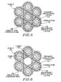
- they may be placed together in parallel, ribbon-like arrangement, as noted in block20 of FIG. 2 and illustrated in FIG. 3, or they may be grouped together in a helical stranded arrangement such as any of those shown in FIGS. 4, 5, and 6, as indicated in block 22 of FIG. 2.
- a cable 24 includes five conductors 12, each having a primary coating 14 and a secondary coating 16 of insulating materials. All are coated furtherwith a third layer, or overcoating 26, of an electrically insulating material which should also be compatible with implantation into a living body.
- the overcoating 26 may, for example, be of a polyesterimide material similar to that of the secondary layer 16. Use of such material as the overcoating 26 is convenient for its ability to be removed from the individual conductors 12 which have been coated with the primary and secondary layers 14 and 16.
- the overcoating 26 coats the individual conductors 12, overthe primary and secondary layers 14 and 16 of insulating material, and joins the conductors 12 to one another as shown in FIG. 3, to produce a planar, ribbon-like cable 24 having a total width 28 of about 265 microns, or about 0.01 inch.
- Groups of individual conductors 12 may also be arranged as a round cable, preferably twisted tightly enough to keep all of the conductors together.
- a 0.070-inch lay pitch for a cable diameter of 0.001 inch has been found satisfactory to maintain a helical arrangement configured, for example, as shown in FIGS. 4, 5, and 6.
- a cable 30 includes seven individual conductors 12, each coated by a primary layer of insulating material 14 and a secondary layer 16. This stranding can be performed using a planetary or non-planetary cabler. The entire group of conductors 12 is held together as the cable 30 merely by the effect of the helical twist.
- Such an arrangement allows the individual conductors 12 to flex and, to some extent, to move longitudinally with respect to one another to promote flexibility of the entire cable 30, allowing the cable 30 to bend in response to a minimum of bending force consistent with having the individual conductors 12 insulated electrically.
- a generally circular cable 10 a grouping of seven conductors 12 with their coatings 14 and 16 of primary and secondary insulating materials, may be provided furt her wit a third or outer layer, or overcoating 38, of an insulating material, as shown by step 40 in FIG. 2.
- the overcoatings 26 or 38 may also be of other materials which can be removed without damage to the particular primary layer 14 of insulating material.
- polyurethane dissolved in a suitable solvent system such as tetrahydrofuran or dimethylacetamide or similar solvent mixtures may be used to overcoat a stranded or ribbonized cable whose conductors 12 are coated with a primary layer 14 of the polyimide, silicone, PTFE, PFA, FEP, or amorphous perfluorocarbon polymer (TEFLON AF) materials previously mentioned as suitable for the primary layer 14.
- TEFLON AF amorphous perfluorocarbon polymer
- some polymeric fluorocarbons such as the previously-mentioned amorphous perfluorocarbon available from E.I. DuPont under the trademark TEFLON AF, may be dissolved in certain perfluoronated solvents such as that available from 3-M Company of Minneapolis, Minnesota under the trade name Fluorinert FC-75. This solution may then be applied to deposit the overcoat layer 38 or 26 for a stranded or ribbonized cable whose conductors 12 have a primary layer 14 of the silicone, polyurethane, polyimide, PTFE, FEP, or PFA materials mentioned previously as being useful as a primary layer 14.
- silicone polymer dispersions or solutions are also suitable to use as the overcoating layer 26 or 38 for a stranded or ribbonized cable according to the invention, where the individual conductors 12 have a primary layer 14 of one of the polyimide, PTFE, FEP, PFA, or amorphous perfluorocarbon (TEFLON AF) insulating materials mentioned previously as being satisfactory for use as such a primary layer 14.
- Medical grade silicones such as Dow Corning MDX4-4210 or Silastic Q7-2245, both available from the Dow Corning Corp. of Midland, Michigan, may suitably be dispersed or dissolved in certain suitable solvents such as xylene, toluene, or VM & P naphtha and used to overcoat such a stranded or ribbonized cable.
- a cable 42 in a cable 42 six individual conductors 12, each individually coated with a primary insulating material 14 and a secondary coating 16 of insulating materials, are formed into a generally circular cable 42 including an extremely small tube 43 defining a lumen 44 surrounded by individual conductors 12 held together by an overcoating 46 of a dielectric insulating material such as the previously described polyesterimide, polyurethane, or silicone materials.
- the tube 43 can, for example, be a tube formed of a polyimide material and available from Hudson International, Specialty Products Division, of Trenton, Georgia, in sizes as small as an outside diameter of .0041 inch and a lumen diameter of .0031 inch.
- the cable 42 can thus function as an extremely small catheter.
- the conductors 12 of the cable 42 are preferably helically twisted together as a strand to help maintain the round configuration of the cable 42 including the centrally located tube 43.
- the individual conductors 12 can be coated with the coating 14 of primary insulation, and a secondary coating of insulation 16, if desired, and may thereafter be prepared as cables with a required number of individual conductors 12 either twisted together or arranged in a planar, ribbon-like configuration or twisted cable configuration and adhered to one another by an overcoating layer as described previously to produce cable material in long lengths.
- the cable may be cut to desired lengths for particular applications and the terminal portion at each end of a chosen length of cable material can be prepared to provide for electrical connection to a printed circuit or set of terminal pads by providing the required pitch between adjacent ones of the conductors 12 at the terminal portion of the cable.
- the ends of a cable according to the invention are prepared to include terminal portions 48.
- the several individual conductors 12 are held in a cable terminal configuration in which parts of the individual conductors 12 are exposed for electrical connection and are held evenly spaced apart from one another with a pitch corresponding to the pitch between exposed terminal pads or conductors of an electrical circuit to which the cable is to be connected.
- the overcoating of insulating dielectric material must be removed from a terminal portion 48 of the cable, as indicated by step 50 of FIG. 2, and the terminal portions of the individual conductors 12 must be separated from one another, as indicated in steps 50 and 52 shown in FIG. 2. It is also acceptable to remove the secondary layer 16 of insulating material from the portions of the individual conductors 12 to be included in the terminal portion of the cable if such a layer is present, but the primary layer 14 of insulating material is preferably kept intact.
- the overcoating or third layer 26, 38 or 46 of insulating material can be removed from the terminal portion 48 of a cable such as the stranded cable 10, for example, by providing a stream of heated air, hot enough to melt or even char such an overcoating layer 38.
- the secondary layer 16 of insulating material may similarly be removed from each of the individual conductors 12 at the same time, but need not be so removed.
- the primary insulation layer 14 is left undamaged because of its higher melting and decomposition temperatures.
- the polyesterimide overcoat 38 and the secondary layer 16 of insulating material of the individual conductors 12 may be removed from the terminal portion 48 of the cable 10 by the use of a solvent which acts on the polyesterimide insulating material without damaging the primary insulating coating 14 of polyimide.
- a solvent which acts on the polyesterimide insulating material without damaging the primary insulating coating 14 of polyimide.
- Three solvents which have been determined to be superior in selectively attacking an overcoat layer26, 38, or 46 and secondary layer 16 of polyesterimide are N-methylpyrrolidinone, 1,1,2,2-tetrachioroethane, and cresylic acid.
- the solvent should be heated to 100-150°C (depending on solvent volatility).
- the terminal portion of the cable 10 is then placed in the hot solvent for a sufficient time, usually less than three minutes, for the solvent to soften and swell the polyesterimide material.
- the softened material can then be removed easily from the terminal portions of the conductors 12 by brushing it away with a tool such as the back of a scalpel, taking care not to damage the individual conductors 12 in the process. This leaves the individual conductors 12 in the terminal portion 48 of the cable 10 free to be manipulated separately to prepare the cable 10 for termination.
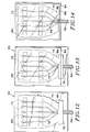
- step 60 in FIG. 2 the separated terminal portions of the conductors 12 at an end of the cable are placed in a terminal preparation, or ribbonization, fixture 62 shown in FIGS. 9, 10, and 11, and as indicated in step 60 in FIG. 2.
- the ribbonization fixture 62 includes a base 64 having a flat horizontal upper surface 66 upon which are located several spacer pads 68, which may be of generally rectangular shape and which are, for example, formed integrally with the base 64.
- the spacer pads 68 are preferably aligned with one another in a row aligned transversely with respect to the conductors 12.
- Each spacer pad 68 preferably has the appropriate width 70 to leave gaps 72 between adjacent spacer pads 68, providing the desired separation distance, or pitch 74, between consecutive ones of the conductors 12 of a cable, such as the cable 10, to facilitate electrical connection of the cable to a printed circuit.
- the terminal portion 48 of the cable is placed atop the base 64 of the ribbonization fixture 62.
- the individual conductors 12 are manipulated, making them diverge from each other in a transition portion 75, as by using tweezers, to place each of the individual conductors 12 into a respective one of the gaps 72, with the conductors lying substantially flat along the upper surface 66 of the base 64.
- a row of rear spacer pads 78 similar to the spacer pads 68, are separated from each other and located aligned with respective ones of the spacer pads 68 adjacent the transition portion 75 to hold the conductors 12 similarly in gaps 79, maintaining parallelism between the conductors 12.
- All of the spacer pads 68 and 78 preferably have the same height 80, as is best seen in FIGS. 10 and 11.
- the still-overcoated portion of the cable 10, 24, 30, or42 which remains helically twisted or in flat planar ribbon form, is held down on the base 64 of the ribbonization fixture, as by use of a small strip 76 of an adhesive tape overlying the cable and adhering to the surface 66 on each side of the cable.
- a quantity of a resin material is cured surrounding transition portion 75 and the terminal portions of the conductors 12 to ribbonize the terminal portion 48 of the cable 10, as indicated as step 82 in FIG. 2.
- a cover sheet 84 of a material which is transparent to ultraviolet light is placed over a small quantity of uncured resin material 86, with the cover sheet 84 supported by the spacer pads 68 and the rear spacer pads 78 so that the flat cover sheet 84 shapes the resin material 86 to provide a flat upper surface while the resin is cured by application of high intensity ultraviolet light.
- the cover sheet 84 may, for example, be a glass microscope slide cover.
- the cable end assembly is removed from the ribbonization fixture 62 and may be turned over to expose what had been the underside, which had been resting on the surface 66 of the ribbonization fixture 62.
- an additional controlled amount of resin 86 may then be applied and covered by a second slide cover sheet 88, also transparent to ultraviolet light, to form a second flat surface defined by the second cover sheet 88, with the additional resin material filling and covering the indentations 89 previously made by the spacer elements 68 and 78 which had been used to hold the individual coated conductors 12 properly aligned parallel with each other at the desired pitch 74.
- the second quantity of resin material 86 is then also cured, as by exposure to high intensity ultraviolet light.
- Asuitable resin material 86 for forming such a ribbonized cable terminal portion 48 has been found to be a medical grade UV-curable silicone available, for example, from Dymax Corp. of Torrington, Connecticut, as its DymaxTM UV-curable silicone No. 20234, which can be cured by brief exposure to high intensity ultraviolet light.
- the cover sheets 84 and 88 are carefully removed and the ultraviolet-cured resin is trimmed, as indicated as step 90 in FIG. 2, to leave the terminal portion 48 of the cable preferably in the form such as that shown in FIGS. 1 and 15 of the drawings.
- trimming of the ultraviolet-cured resin material 86 is best accomplished initially by use of a precision cutting die to provide a shape such as that shown in FIG. 15. Thereafter, portions of the individual conductors 12 are bared to permit electrical connection, preferably in an accurately machine-controlled manner such as by the use of a computer-controlled laser beam scanned across the ribbonized terminal portion of the cable, sweeping in a direction perpendicular to the length of the portions of the individual conductors 12 which had been held in the gaps 72 of the fixture 62.
- multiple sweeps of the laser beam using a low power laser such as a 25 watt C0 2 laser available from Synrad, Inc., of Bothell, Washington, are used to remove the excess cured ribbonizing encapsulation resin material and the primary layer 14 of insulating material without damaging the conductors.
- a low power laser such as a 25 watt C0 2 laser available from Synrad, Inc., of Bothell, Washington
- the laser may be used to remove ribbonization resin material 86 and any remaining material of secondary and primary layers 16, 14, baring portions 92 of the individual conductors 12 while leaving the conductors 12 supported on each end of each portion 92 by a quantity of the ribbonization resin 86.
- the ribbonization material and the secondary and primary insulation layers may be removed at the distal end of the ribbonized terminal portion of the cable as shown in FIG. 17.
- insulating material such as polyimide used as the primary layer 14 on each of the conductors 12 is somewhat resistant to removal by laser radiation, it may be necessary to remove residue of such a layer 14 by ultrasonic cleaning with a detergent and distilled water, in order to leave a clean and bare metal surface on each of the individual conductors 12.
- Electrical connection of the individual conductors 12 may be accomplished by placing the prepared terminal portion 48 of the cable properly in registration with terminal pads or printed circuit conductor traces on a printed circuit to which the cable is intended to be connected and effecting connection by conventional techniques such as suitable wire-bonding techniques.
- the steps of preparing and ultimately connecting the terminal portion 48 of the cable are similar when the primary layer 14 is of another insulating material such as a layer of Teflon (PTFE), silicone, or polyurethane material, the critical steps being removal of overcoating material causing the insulated individual conductors 12 to adhere to each other, establishing the required pitch between terminal portions of the conductors 12, applying, curing, and trimming a ribbonizing material 86 to maintain the positions of the conductors 12, and then baring the portions of the conductors 12 to be connected electrically.
- PTFE Teflon
Landscapes
- Health & Medical Sciences (AREA)
- Engineering & Computer Science (AREA)
- Life Sciences & Earth Sciences (AREA)
- Biomedical Technology (AREA)
- General Health & Medical Sciences (AREA)
- Animal Behavior & Ethology (AREA)
- Veterinary Medicine (AREA)
- Public Health (AREA)
- Neurology (AREA)
- Heart & Thoracic Surgery (AREA)
- Radiology & Medical Imaging (AREA)
- Physics & Mathematics (AREA)
- Nuclear Medicine, Radiotherapy & Molecular Imaging (AREA)
- Orthopedic Medicine & Surgery (AREA)
- Cardiology (AREA)
- Manufacturing & Machinery (AREA)
- Physiology (AREA)
- Neurosurgery (AREA)
- Acoustics & Sound (AREA)
- Biophysics (AREA)
- Otolaryngology (AREA)
- Psychology (AREA)
- Vascular Medicine (AREA)
- Insulated Conductors (AREA)
Applications Claiming Priority (2)
| Application Number | Priority Date | Filing Date | Title |
|---|---|---|---|
| US07/781,494 US5201903A (en) | 1991-10-22 | 1991-10-22 | Method of making a miniature multi-conductor electrical cable |
| US781494 | 1991-10-22 |
Publications (2)
| Publication Number | Publication Date |
|---|---|
| EP0539148A2 true EP0539148A2 (de) | 1993-04-28 |
| EP0539148A3 EP0539148A3 (en) | 1993-09-15 |
Family
ID=25122926
Family Applications (1)
| Application Number | Title | Priority Date | Filing Date |
|---|---|---|---|
| EP19920309556 Withdrawn EP0539148A3 (en) | 1991-10-22 | 1992-10-20 | Miniature biologically implantable cable assembly |
Country Status (2)
| Country | Link |
|---|---|
| US (1) | US5201903A (de) |
| EP (1) | EP0539148A3 (de) |
Cited By (17)
| Publication number | Priority date | Publication date | Assignee | Title |
|---|---|---|---|---|
| EP0831564A3 (de) * | 1996-09-09 | 1999-03-10 | Nec Corporation | Herstellungsverfahren eines Kunststoffspritzgussbauteils mit Anschlüssen |
| EP0768739A3 (de) * | 1995-10-10 | 2000-03-29 | W.L. GORE & ASSOCIATES GmbH | Konfektioniertes Kabel, Herstellungsverfahren dafür sowie mit konfektioniertem Kabel versehenes Hörgerät |
| EP1096509A3 (de) * | 1999-10-26 | 2002-04-24 | Sumitomo Electric Industries, Ltd. | Mehrleiterkabel |
| US6516173B1 (en) * | 2001-08-17 | 2003-02-04 | Xerox Corporation | Ion implantation to tune tribo-charging properties of materials or hybrid scavengless development wires |
| WO2003098643A1 (de) * | 2002-05-15 | 2003-11-27 | Studer Draht- Und Kabelwerk Ag | Strangförmiges produkt mit anschluss- und/oder befestigungsmitteln |
| WO2005007235A1 (en) * | 2003-07-22 | 2005-01-27 | Epic Biosonics, Inc. | Implantable electrical cable and method of making |
| WO2003089045A3 (en) * | 2002-04-11 | 2005-02-10 | Medtronic Inc | Implantable medical lead conductor insulation |
| GB2415835A (en) * | 2004-06-30 | 2006-01-04 | Contactum Ltd | Cable end alignment for connection |
| WO2006017421A1 (en) * | 2004-08-02 | 2006-02-16 | Medtronic, Inc. | Implantable medical device conductor insulation and process for forming |
| WO2007053253A1 (en) * | 2005-11-07 | 2007-05-10 | Gore Enterprise Holdings, Inc. | Implantable electrophysiology lead body |
| EP1847291A1 (de) * | 1998-11-09 | 2007-10-24 | Medtronic, Inc. | Extrahierbare und implantierbare medizinische Elektrode |
| EP1763284A3 (de) * | 1997-07-18 | 2009-08-12 | Resound Corporation | Hinter-dem-Ohr-Hörhilfesystem |
| CN101976597A (zh) * | 2010-08-03 | 2011-02-16 | 昆山市七浦电刷线有限公司 | 一种复合型软铜绞线 |
| US8103358B2 (en) | 2003-04-04 | 2012-01-24 | Medtronic, Inc. | Mapping guidelet |
| US8271100B2 (en) | 2004-04-23 | 2012-09-18 | Medtronic, Inc. | Medical device conductor junctions |
| EP2079513A4 (de) * | 2006-10-31 | 2013-02-13 | St Jude Medical | Medizinische implantierbare leitung mit einem flexiblen flachen gedrehten länglichen körper |
| EP3812004A1 (de) * | 2019-10-23 | 2021-04-28 | BIOTRONIK SE & Co. KG | Hermetische durchführung mit spiralförmig gerollter leiteranordnung |
Families Citing this family (51)
| Publication number | Priority date | Publication date | Assignee | Title |
|---|---|---|---|---|
| DE69307873T2 (de) * | 1992-04-10 | 1997-08-07 | Cardiorhythm | Herzkatheter zur messung eines bezugspotentials |
| US5560884A (en) * | 1992-11-23 | 1996-10-01 | Esterline Technologies Corporation | Method of producing a molded woven cable |
| WO1994021170A1 (en) * | 1993-03-16 | 1994-09-29 | Ep Technologies, Inc. | Flexible circuit assemblies employing ribbon cable |
| US5476495A (en) * | 1993-03-16 | 1995-12-19 | Ep Technologies, Inc. | Cardiac mapping and ablation systems |
| DE19507793C1 (de) * | 1995-03-06 | 1996-04-25 | Siemens Nixdorf Inf Syst | Laminierung einer Adernausbündelung |
| US5923803A (en) * | 1997-07-28 | 1999-07-13 | Molex Incorporated | Method of fabricating a fiber optic connector ferrule |
| US5867620A (en) * | 1997-07-28 | 1999-02-02 | Molex Incorporated | Fixture for fabricating a fiber optic connector ferrule |
| US5963691A (en) * | 1997-07-28 | 1999-10-05 | Molex Incorporated | Alignment system in a connector ferrule for a fiber optic cable |
| US5907651A (en) * | 1997-07-28 | 1999-05-25 | Molex Incorporated | Fiber optic connector ferrule |
| US5925069A (en) * | 1997-11-07 | 1999-07-20 | Sulzer Intermedics Inc. | Method for preparing a high definition window in a conformally coated medical device |
| US6232557B1 (en) * | 1997-11-07 | 2001-05-15 | Rockwell Technologies, Llc | Network cable and modular connection for such a cable |
| WO1999029004A1 (en) * | 1997-11-28 | 1999-06-10 | Furukawa Electric Co., Ltd. | Rotary connector |
| US6052608A (en) * | 1998-03-30 | 2000-04-18 | Johnson & Johnson Professional, Inc. | Implantable medical electrode contacts |
| US6296725B1 (en) | 1998-09-29 | 2001-10-02 | Litton Systems, Inc. | High frequency ribbon cable for twist capsule cable applications |
| US20020104668A1 (en) * | 2000-05-01 | 2002-08-08 | Lear Corporation | Method and apparatus for making an electrical distribution conductor and resultant product |
| JP4064045B2 (ja) * | 2000-09-01 | 2008-03-19 | 株式会社日立製作所 | 樹脂ブロック絶縁システム |
| US20030236562A1 (en) * | 2000-10-10 | 2003-12-25 | Kuzma Janusz A. | Band type multicontact electrode and method of making the same |
| AU2003210471A1 (en) * | 2002-01-09 | 2003-07-30 | Thomas And Betts International, Inc. | Semiconductive coating and application process for shielded elastomeric electrical cable accessories |
| US8396568B2 (en) * | 2002-04-11 | 2013-03-12 | Medtronic, Inc. | Medical electrical lead body designs incorporating energy dissipating shunt |
| US7904178B2 (en) * | 2002-04-11 | 2011-03-08 | Medtronic, Inc. | Medical electrical lead body designs incorporating energy dissipating shunt |
| JP2006516335A (ja) * | 2002-08-21 | 2006-06-29 | ニューヨーク・ユニバーシティ | 脳と機械のインターフェースのシステムおよび方法 |
| US7411127B2 (en) * | 2003-02-18 | 2008-08-12 | Medconx, Inc. | Electrical wire and a method of stripping the insulation thereof |
| US20040215299A1 (en) * | 2003-04-23 | 2004-10-28 | Medtronic, Inc. | Implantable medical device conductor insulation and process for forming |
| JP4896367B2 (ja) * | 2003-10-23 | 2012-03-14 | パナソニック株式会社 | 電子部品の処理方法及び装置 |
| US20070250143A1 (en) * | 2006-04-19 | 2007-10-25 | Sommer John L | Multi-conductor ribbon coiled medical device lead |
| US20100016935A1 (en) * | 2006-10-25 | 2010-01-21 | Hans Strandberg | Medical implantable lead |
| US20080183074A1 (en) * | 2007-01-25 | 2008-07-31 | Warsaw Orthopedic, Inc. | Method and apparatus for coordinated display of anatomical and neuromonitoring information |
| US20080183188A1 (en) * | 2007-01-25 | 2008-07-31 | Warsaw Orthopedic, Inc. | Integrated Surgical Navigational and Neuromonitoring System |
| US7987001B2 (en) * | 2007-01-25 | 2011-07-26 | Warsaw Orthopedic, Inc. | Surgical navigational and neuromonitoring instrument |
| US8374673B2 (en) * | 2007-01-25 | 2013-02-12 | Warsaw Orthopedic, Inc. | Integrated surgical navigational and neuromonitoring system having automated surgical assistance and control |
| US20080183068A1 (en) * | 2007-01-25 | 2008-07-31 | Warsaw Orthopedic, Inc. | Integrated Visualization of Surgical Navigational and Neural Monitoring Information |
| US10842653B2 (en) | 2007-09-19 | 2020-11-24 | Ability Dynamics, Llc | Vacuum system for a prosthetic foot |
| US8726492B2 (en) * | 2009-09-09 | 2014-05-20 | Cochlear Limited | Insulated conductive element having a substantially continuous barrier layer formed through multiple coatings |
| CN102597298B (zh) * | 2009-09-09 | 2014-09-17 | 耳蜗有限公司 | 具有通过多个涂层形成的基本上连续的阻挡层的绝缘传导元件 |
| US8460746B2 (en) * | 2009-09-09 | 2013-06-11 | Cochlear Limited | Method of forming insulated conductive element having a substantially continuous barrier layer formed via relative motion during deposition |
| US8545926B2 (en) * | 2009-09-09 | 2013-10-01 | Cochlear Limited | Method of forming insulated conductive element having substantially continuously coated sections separated by uncoated gaps |
| US8620399B2 (en) * | 2010-12-30 | 2013-12-31 | St. Jude Medical, Atrial Fibrillation Division, Inc. | Deflectable medical devices and methods of manufacturing therefor |
| JP2013131423A (ja) * | 2011-12-22 | 2013-07-04 | Hitachi Cable Ltd | 絶縁電線及びコイル |
| US8666511B2 (en) | 2012-07-30 | 2014-03-04 | Medtronic, Inc. | Magnetic resonance imaging compatible medical electrical lead and method of making the same |
| WO2014031313A2 (en) * | 2012-08-20 | 2014-02-27 | Boston Scientific Scimed, Inc. | Electronic cable assemblies for use with medical devices |
| US9579806B2 (en) * | 2012-08-23 | 2017-02-28 | Rethink Robotics, Inc. | Robotic power and signal distribution using laminated cable with separator webs |
| CN103680384B (zh) * | 2012-09-26 | 2016-05-11 | 乐金显示有限公司 | 具有柔性膜线缆的显示装置 |
| GB2532044A (en) * | 2014-11-06 | 2016-05-11 | Phagenesis Ltd | Catheter for recovery of dysphagia |
| GB201513989D0 (en) | 2015-08-07 | 2015-09-23 | Phagenesis Ltd | Method of diagnosis of dysphagia |
| GB2544780A (en) | 2015-11-26 | 2017-05-31 | Phagenesis Ltd | Devices and methods for treatment of ventilator associated dysphagia |
| CN109152873B (zh) | 2016-03-02 | 2021-03-16 | 心脏器械股份有限公司 | 具有扁平线缆的皮肤按钮 |
| CA3082476A1 (en) | 2017-11-13 | 2019-05-16 | Essex Group, Inc. | Winding wire articles having internal cavities |
| WO2022106844A1 (en) | 2020-11-19 | 2022-05-27 | Phagenesis Limited | Devices, systems, and methods for treating disease using electrical stimulation |
| US11992681B2 (en) | 2020-11-20 | 2024-05-28 | Phagenesis Limited | Devices, systems, and methods for treating disease using electrical stimulation |
| US12491362B2 (en) | 2020-11-20 | 2025-12-09 | Phagenesis Limited | Devices, systems, and methods for treating and preventing disease |
| US12088029B2 (en) * | 2021-07-20 | 2024-09-10 | Dell Products L.P. | Cable termination for information handling systems |
Family Cites Families (26)
| Publication number | Priority date | Publication date | Assignee | Title |
|---|---|---|---|---|
| FR1221818A (fr) * | 1959-01-14 | 1960-06-03 | Canalisation électrique préfabriquée pour colonne d'immeuble | |
| US3605060A (en) * | 1968-08-05 | 1971-09-14 | Honeywell Inc | Apparatus for terminating electrical ribbon cable |
| DE2212091A1 (de) * | 1972-03-13 | 1973-09-20 | Siemens Ag | Anschlusskabel |
| DE2344371C2 (de) * | 1972-03-13 | 1982-09-09 | Siemens AG, 1000 Berlin und 8000 München | Anschlußkabel |
| US3881246A (en) * | 1973-12-12 | 1975-05-06 | Amp Inc | Method and apparatus for facilitating the positioning of the free end sections of a plurality of leads in a plurality of grooves |
| US3874077A (en) * | 1973-12-12 | 1975-04-01 | Amp Inc | Method and apparatus for centering and shearing the free end portion of a plurality of leads which extend outwardly from one end of a template |
| DK516577A (da) * | 1977-11-22 | 1979-05-23 | C C Hansen | Elektrode til tilsaetning i oerets snegl (cochlea) |
| AU529974B2 (en) * | 1978-05-04 | 1983-06-30 | University Of Melbourne, The | Electrode for human cochlea |
| US4614028A (en) * | 1982-03-17 | 1986-09-30 | Thomas & Betts Corporation | Electrical assembly and method for arranging a plurality of electrical conductors in a pattern |
| US4495917A (en) * | 1982-03-26 | 1985-01-29 | The Regents Of The University Of California | Surgically implantable disconnect device |
| US4537804A (en) * | 1982-05-05 | 1985-08-27 | General Electric Company | Corona-resistant wire enamel compositions and conductors insulated therewith |
| US4503124A (en) * | 1982-05-05 | 1985-03-05 | General Electric Company | Corona-resistant wire enamel compositions and conductors insulated therewith |
| US5105811A (en) * | 1982-07-27 | 1992-04-21 | Commonwealth Of Australia | Cochlear prosthetic package |
| US4532930A (en) * | 1983-04-11 | 1985-08-06 | Commonwealth Of Australia, Dept. Of Science & Technology | Cochlear implant system for an auditory prosthesis |
| CH662669A5 (de) * | 1984-04-09 | 1987-10-15 | Straumann Inst Ag | Leitvorrichtung zum mindestens teilweisen einsetzen in einen menschlichen oder tierischen koerper, mit einer zumindest aus einem leiter gebildeten wendel. |
| US4809712A (en) * | 1986-09-26 | 1989-03-07 | Cochlear Pty. Ltd. | Electrode assembly for cochlear implant |
| EP0293499B1 (de) * | 1987-06-01 | 1993-09-01 | Siemens-Elema AB | Implantierbare vielpolige koaxiale Leitung |
| JPH066115B2 (ja) * | 1987-08-27 | 1994-01-26 | 新技術事業団 | 生体内埋込用電極 |
| US4819329A (en) * | 1987-09-09 | 1989-04-11 | Innovex Inc. | Method of manufacturing multiwire lead assemblies |
| FR2629710B1 (fr) * | 1988-04-08 | 1997-10-24 | Mxm | Dispositifs porte-electrodes implantables dans la cochlee pour stimuler electriquement le nerf auditif |
| JPH0265941U (de) * | 1988-11-07 | 1990-05-17 | ||
| US5067903A (en) * | 1989-11-20 | 1991-11-26 | Siemens-Pacesetter, Inc. | Ribbon conductor set and method |
| US5111812A (en) * | 1990-01-23 | 1992-05-12 | Cardiac Pacemakers, Inc. | Defilbrillation electrode having smooth current distribution |
| DE4004229A1 (de) * | 1990-02-12 | 1991-08-14 | Wilhelm Kraemer | Flach/rundkabel |
| US5074808A (en) * | 1991-02-06 | 1991-12-24 | Amp Incorporated | Molded strain relief in back shell |
| GB9522219D0 (en) * | 1995-10-31 | 1996-01-03 | Advanced Systems Ltd | Ultraviolet sensing apparatus |
-
1991
- 1991-10-22 US US07/781,494 patent/US5201903A/en not_active Expired - Fee Related
-
1992
- 1992-10-20 EP EP19920309556 patent/EP0539148A3/en not_active Withdrawn
Cited By (28)
| Publication number | Priority date | Publication date | Assignee | Title |
|---|---|---|---|---|
| EP0768739A3 (de) * | 1995-10-10 | 2000-03-29 | W.L. GORE & ASSOCIATES GmbH | Konfektioniertes Kabel, Herstellungsverfahren dafür sowie mit konfektioniertem Kabel versehenes Hörgerät |
| EP0831564A3 (de) * | 1996-09-09 | 1999-03-10 | Nec Corporation | Herstellungsverfahren eines Kunststoffspritzgussbauteils mit Anschlüssen |
| US6096259A (en) * | 1996-09-09 | 2000-08-01 | Nec Corporation | Fabrication method of plastic-molded lead component |
| EP1763284A3 (de) * | 1997-07-18 | 2009-08-12 | Resound Corporation | Hinter-dem-Ohr-Hörhilfesystem |
| EP1847291A1 (de) * | 1998-11-09 | 2007-10-24 | Medtronic, Inc. | Extrahierbare und implantierbare medizinische Elektrode |
| EP1096509A3 (de) * | 1999-10-26 | 2002-04-24 | Sumitomo Electric Industries, Ltd. | Mehrleiterkabel |
| US6516173B1 (en) * | 2001-08-17 | 2003-02-04 | Xerox Corporation | Ion implantation to tune tribo-charging properties of materials or hybrid scavengless development wires |
| US8209032B2 (en) | 2002-04-11 | 2012-06-26 | Medtronic, Inc. | Implantable medical device conductor insulation and process for forming |
| WO2003089045A3 (en) * | 2002-04-11 | 2005-02-10 | Medtronic Inc | Implantable medical lead conductor insulation |
| US7783365B2 (en) | 2002-04-11 | 2010-08-24 | Medtronic, Inc. | Implantable medical device conductor insulation and process for forming |
| CH696011A5 (de) * | 2002-05-15 | 2006-11-15 | Studer Ag Draht & Kabelwerk | Strangförmiges Produkt mit Anschluss- und/oder Befestigungsmitteln. |
| US7154038B2 (en) | 2002-05-15 | 2006-12-26 | Studer Draht - Und Kabelwerk Ag | String-shaped product with connecting and/or fixing means |
| WO2003098643A1 (de) * | 2002-05-15 | 2003-11-27 | Studer Draht- Und Kabelwerk Ag | Strangförmiges produkt mit anschluss- und/oder befestigungsmitteln |
| US8103358B2 (en) | 2003-04-04 | 2012-01-24 | Medtronic, Inc. | Mapping guidelet |
| WO2005007235A1 (en) * | 2003-07-22 | 2005-01-27 | Epic Biosonics, Inc. | Implantable electrical cable and method of making |
| US8271100B2 (en) | 2004-04-23 | 2012-09-18 | Medtronic, Inc. | Medical device conductor junctions |
| GB2415835A (en) * | 2004-06-30 | 2006-01-04 | Contactum Ltd | Cable end alignment for connection |
| GB2415835B (en) * | 2004-06-30 | 2008-05-28 | Contactum Ltd | Cable connection method |
| WO2006017421A1 (en) * | 2004-08-02 | 2006-02-16 | Medtronic, Inc. | Implantable medical device conductor insulation and process for forming |
| US7630749B2 (en) | 2005-11-07 | 2009-12-08 | Gore Enterprise Holdings, Inc. | Implantable electrophysiology lead body |
| AU2006343538B2 (en) * | 2005-11-07 | 2010-09-23 | W. L. Gore & Associates, Inc. | Implantable electrophysiology lead body |
| WO2007133253A1 (en) * | 2005-11-07 | 2007-11-22 | Gore Enterprise Holdings, Inc. | Implantable electrophysiology lead body |
| WO2007053253A1 (en) * | 2005-11-07 | 2007-05-10 | Gore Enterprise Holdings, Inc. | Implantable electrophysiology lead body |
| US8437830B2 (en) | 2005-11-07 | 2013-05-07 | W. L. Gore & Associates, Inc. | Implantable electrophysiology lead body |
| US8442612B2 (en) | 2005-11-07 | 2013-05-14 | W. L. Gore & Associates, Inc. | Implantable electrophysiology lead body |
| EP2079513A4 (de) * | 2006-10-31 | 2013-02-13 | St Jude Medical | Medizinische implantierbare leitung mit einem flexiblen flachen gedrehten länglichen körper |
| CN101976597A (zh) * | 2010-08-03 | 2011-02-16 | 昆山市七浦电刷线有限公司 | 一种复合型软铜绞线 |
| EP3812004A1 (de) * | 2019-10-23 | 2021-04-28 | BIOTRONIK SE & Co. KG | Hermetische durchführung mit spiralförmig gerollter leiteranordnung |
Also Published As
| Publication number | Publication date |
|---|---|
| EP0539148A3 (en) | 1993-09-15 |
| US5201903A (en) | 1993-04-13 |
Similar Documents
| Publication | Publication Date | Title |
|---|---|---|
| US5201903A (en) | Method of making a miniature multi-conductor electrical cable | |
| US5515848A (en) | Implantable microelectrode | |
| RU2452529C2 (ru) | Способ изготовления цепи нейростимуляции и цепь нейростимуляции | |
| EP1651305B1 (de) | Implantierbare elektrische kabelvorrichtung und deren herstellungsverfahren | |
| US9263172B2 (en) | Wire constructs | |
| Hetke et al. | Silicon ribbon cables for chronically implantable microelectrode arrays | |
| AU2003303795B2 (en) | Implantable medical assembly using a corrugated film | |
| KR102565073B1 (ko) | 가이드와이어상에 전기활성 팁을 포함하는 도입 장치 | |
| US5782645A (en) | Percutaneous connector for multi-conductor electrical cables | |
| US20060142652A1 (en) | Concepts using the improved "composite flexible and conductive catheter electrode bands" and their method of construction | |
| WO1999049934A1 (en) | Implantable medical electrode comprising a flexible printed circuit | |
| JP2000502922A (ja) | 埋植型電極のための薄膜製作技術 | |
| EP3542854A1 (de) | Herstellungsverfahren für ein multielektrodensystem | |
| EP3542853B1 (de) | Herstellungsverfahren für eine mikroleitung | |
| Guo et al. | Implementation of integratable PDMS-based conformable microelectrode arrays using a multilayer wiring interconnect technology |
Legal Events
| Date | Code | Title | Description |
|---|---|---|---|
| PUAI | Public reference made under article 153(3) epc to a published international application that has entered the european phase |
Free format text: ORIGINAL CODE: 0009012 |
|
| AK | Designated contracting states |
Kind code of ref document: A2 Designated state(s): CH DE FR GB LI |
|
| PUAL | Search report despatched |
Free format text: ORIGINAL CODE: 0009013 |
|
| AK | Designated contracting states |
Kind code of ref document: A3 Designated state(s): CH DE FR GB LI |
|
| 17P | Request for examination filed |
Effective date: 19940310 |
|
| 17Q | First examination report despatched |
Effective date: 19940905 |
|
| 18D | Application deemed to be withdrawn |
Effective date: 19950116 |