EP0539320A1 - Dispositif de commande hydraulique d'une soupape d'échappement d'un moteur à combustion interne à piston - Google Patents
Dispositif de commande hydraulique d'une soupape d'échappement d'un moteur à combustion interne à piston Download PDFInfo
- Publication number
- EP0539320A1 EP0539320A1 EP92810735A EP92810735A EP0539320A1 EP 0539320 A1 EP0539320 A1 EP 0539320A1 EP 92810735 A EP92810735 A EP 92810735A EP 92810735 A EP92810735 A EP 92810735A EP 0539320 A1 EP0539320 A1 EP 0539320A1
- Authority
- EP
- European Patent Office
- Prior art keywords
- line
- pressure medium
- servo
- servo cylinder
- connection
- Prior art date
- Legal status (The legal status is an assumption and is not a legal conclusion. Google has not performed a legal analysis and makes no representation as to the accuracy of the status listed.)
- Granted
Links
Images
Classifications
-
- F—MECHANICAL ENGINEERING; LIGHTING; HEATING; WEAPONS; BLASTING
- F01—MACHINES OR ENGINES IN GENERAL; ENGINE PLANTS IN GENERAL; STEAM ENGINES
- F01L—CYCLICALLY OPERATING VALVES FOR MACHINES OR ENGINES
- F01L1/00—Valve-gear or valve arrangements, e.g. lift-valve gear
- F01L1/12—Transmitting gear between valve drive and valve
- F01L1/14—Tappets; Push rods
- F01L1/16—Silencing impact; Reducing wear
-
- F—MECHANICAL ENGINEERING; LIGHTING; HEATING; WEAPONS; BLASTING
- F15—FLUID-PRESSURE ACTUATORS; HYDRAULICS OR PNEUMATICS IN GENERAL
- F15B—SYSTEMS ACTING BY MEANS OF FLUIDS IN GENERAL; FLUID-PRESSURE ACTUATORS, e.g. SERVOMOTORS; DETAILS OF FLUID-PRESSURE SYSTEMS, NOT OTHERWISE PROVIDED FOR
- F15B11/00—Servomotor systems without provision for follow-up action; Circuits therefor
-
- F—MECHANICAL ENGINEERING; LIGHTING; HEATING; WEAPONS; BLASTING
- F01—MACHINES OR ENGINES IN GENERAL; ENGINE PLANTS IN GENERAL; STEAM ENGINES
- F01L—CYCLICALLY OPERATING VALVES FOR MACHINES OR ENGINES
- F01L9/00—Valve-gear or valve arrangements actuated non-mechanically
- F01L9/10—Valve-gear or valve arrangements actuated non-mechanically by fluid means, e.g. hydraulic
Definitions
- the invention relates to a device for hydraulically actuating an outlet valve of a reciprocating piston internal combustion engine, which at its end facing away from the closure part is operatively connected to a servo piston guided in a servo cylinder, which is acted upon by a hydraulic pressure medium in the valve opening direction during the work cycle of the machine, which is actuated via a Pressure medium line is fed from a pressure medium source to a pressure chamber in the servo cylinder, to which, in addition to the pressure medium line, a relief line and a ventilation line are connected.
- Such a device is known from EP-OS 441 100.
- This device has shown that changes in the length of the exhaust valve stem due to temperature changes change the damping phase when the closure part of the exhaust valve is placed on its seat because the position of the servo piston moves relative to the servo cylinder, which results in a change in the closing point of the exhaust valve. This can adversely affect the operating behavior of the internal combustion engine, particularly in the case of long-stroke internal combustion engines.
- the invention has for its object to improve the device of the type mentioned in such a way that changes in the length of the stem of the exhaust valve no longer have an adverse effect on its closing behavior.
- This object is achieved according to the invention in that between the servo cylinder and the servo piston there is an axially movable guide bush which surrounds this and which has at least one breakthrough communicating with the connection of the pressure medium line and the connection of the relief line on the servo cylinder, and the one facing away from the closure part End is sealed by a transverse wall that between the transverse wall and the front wall of the servo cylinder there is a pressure-filled space, which communicates with the pressure chamber via a check valve that closes against this space and communicates with the ventilation line via a check valve that closes against the ventilation line, and that the pressure chamber is always connected to the connection for the relief line on the servo cylinder.
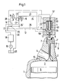
- a working cylinder 1 is formed in the machine housing of a 2-stroke diesel internal combustion engine, and then an exhaust duct 4 is formed in a separate housing 10 at its upper end.
- An outlet valve 2 is arranged in the housing 10 at the entrance of the exhaust duct 4 and, in the closed position shown, separates the combustion chamber 3 in the working cylinder 1 from the exhaust duct 4.
- a working piston 5 is guided up and down.
- the air to be compressed in the working cylinder is admitted into the cylinder chamber via slots (not shown) arranged in the lower region of the working cylinder 1 and is compressed in the combustion chamber 3 during the subsequent upward stroke of the working piston 5.
- the fuel is supplied with the aid of at least one injection nozzle (not shown) projecting into the combustion chamber 3.
- a piston 6 is arranged, which is guided in a cylinder 7 of the housing 10.
- a compressed air line 9 On the in Fig.1 located below the piston 6 cylinder space 7 'is connected via a check valve 8, a compressed air line 9. The air enclosed in this way in the cylinder space 7 'forms an air spring which acts on the exhaust valve 2 in a closing sense.
- the piston 6 in FIG. 1 acts via a rod 11 'a servo piston 11 actuated by a hydraulic pressure medium, which is guided in a servo cylinder 13 to which a hydraulic control device 12 is connected.
- the control device 12 has a pilot valve 15 designed as a 2/2-way valve and actuated by an electromagnet 14 and a 4/2-way valve 16.
- the hydraulic pressure medium for example oil, is supplied to the control device 12 via a line 17 from a pressure medium source 18 designed as an accumulator.
- the accumulator 18 receives the pressure medium from a reservoir 20 by means of a pump 19 which is driven by the crankshaft (not shown) of the internal combustion engine or electrically.
- the pressure medium in the accumulator 18 is under a pressure of, for example, 200 bar.
- the line 17 leading from the accumulator 18 to the control device 12 bifurcates in front of the 4/2-way valve 16 into two line branches 17 'and 17 ⁇ .
- the line branch 17 ⁇ contains a throttle point 22 and leads on the one hand to the pilot valve 15 and on the other hand to an end face of the 4/2-way valve 16.
- a relief line 24 which leads to the 4/2-way valve 16 and continues as a drain line 24 ', which opens into the reservoir 20 via a check valve 25.
- a vent line 26 which branches off from the servo cylinder 13 above the piston 11 and has a throttle point 57.
- a relief line 28 which starts from the pilot valve 15.
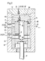
- the servo piston 11 has at its end facing away from the rod 11 'a blind bore 40 which is connected to an annular space 58 at its lower end in FIG. 1 in the region of the connection point 21 via transverse bores 56. In the area of the connection point 23 there is an annular space 59 between the servo piston 11 and the servo cylinder 13.
- a guide bush 60 is arranged between the servo cylinder 13 and the servo piston 11, each of which has a breakthrough in the area of the connection points 21 and 23 in the form of an outer annular groove 61 or 62 and a number of them starting from the circumference the guide sleeve has distributed radial bores 61 'and 62'.
- the guide sleeve 60 is axially movably guided in the servo cylinder 13 and has at its upper end in FIG. 2 a transverse wall 60 'in the form of a cover detachably connected to the guide sleeve.
- a radial channel 72 which opens into an outer annular groove 73 which during an opening process of the exhaust valve during the downward movement of the servo piston relative to the guide sleeve 60 in front of the bore 61 ' is coming.
- the upper end wall 13 'of the servo cylinder 13 in FIG. 2 has a connection point 67 for the vent line 26.
- a pressure medium-filled space 68 which communicates on the one hand via a check valve 69 closing against this space with the pressure chamber 65 and on the other hand via a check valve 70 closing against the connection point 67 with the relief line 26.
- the device according to Fig.2 works as follows. If the stem of the exhaust valve is extended due to an increase in temperature, the rod 11 'of the servo piston 11 is moved upwards in FIG. Since the upper end face of the servo piston 11 rests on the shoulder 63, the guide bush 60 is also displaced upward when the servo piston is moved. As a result of this displacement, pressure medium is displaced from the space 68 into the pressure space 65 via the check valve 69 which opens. The volume of pressure medium thus displaced escapes via the channels 71, 66, the annular groove 62 and the connection point 23 into the relief line 24.
Landscapes
- Engineering & Computer Science (AREA)
- Mechanical Engineering (AREA)
- General Engineering & Computer Science (AREA)
- Physics & Mathematics (AREA)
- Fluid Mechanics (AREA)
- Valve Device For Special Equipments (AREA)
Applications Claiming Priority (2)
| Application Number | Priority Date | Filing Date | Title |
|---|---|---|---|
| CH3098/91 | 1991-10-23 | ||
| CH309891 | 1991-10-23 |
Publications (2)
| Publication Number | Publication Date |
|---|---|
| EP0539320A1 true EP0539320A1 (fr) | 1993-04-28 |
| EP0539320B1 EP0539320B1 (fr) | 1995-01-11 |
Family
ID=4248578
Family Applications (1)
| Application Number | Title | Priority Date | Filing Date |
|---|---|---|---|
| EP92810735A Expired - Lifetime EP0539320B1 (fr) | 1991-10-23 | 1992-09-30 | Dispositif de commande hydraulique d'une soupape d'échappement d'un moteur à combustion interne à piston |
Country Status (6)
| Country | Link |
|---|---|
| EP (1) | EP0539320B1 (fr) |
| JP (1) | JP3564149B2 (fr) |
| KR (1) | KR100222139B1 (fr) |
| CN (1) | CN1032381C (fr) |
| DE (1) | DE59201193D1 (fr) |
| DK (1) | DK0539320T3 (fr) |
Cited By (3)
| Publication number | Priority date | Publication date | Assignee | Title |
|---|---|---|---|---|
| WO1996004469A1 (fr) * | 1994-08-04 | 1996-02-15 | Caterpillar Inc. | Systeme de soupape a commande hydraulique |
| EP1114918A2 (fr) | 2000-01-06 | 2001-07-11 | Wärtsilä NSD Schweiz AG | Commande de soupape pour moteur à combustion interne et mode d'opération |
| WO2002006641A1 (fr) * | 2000-07-14 | 2002-01-24 | Lotus Cars Limited | Systeme de soupape destine a la regulation du debit de gaz entrant ou sortant d'une chambre a volume variable d'un moteur a combustion interne ou d'un compresseur |
Families Citing this family (8)
| Publication number | Priority date | Publication date | Assignee | Title |
|---|---|---|---|---|
| DE10311493B4 (de) * | 2003-03-15 | 2005-01-05 | Man B & W Diesel A/S | Zweitakt-Dieselmotor |
| ITBO20030389A1 (it) * | 2003-06-23 | 2004-12-24 | Magneti Marelli Powertrain Spa | Gruppo elettroidraulico di azionamento delle valvole |
| DE10361221B4 (de) * | 2003-12-24 | 2006-03-09 | Man B&W Diesel A/S | Vorrichtung zur Steuerung der zeitlich versetzten Verbindung von zwei mit einem Druckmittel beaufschlagbaren Aggregaten mit einer Druckmittelquelle |
| US7290509B2 (en) * | 2005-08-01 | 2007-11-06 | Zheng Lou | Variable valve actuator |
| US7587863B2 (en) * | 2006-08-17 | 2009-09-15 | Fike Corporation | Seal for sanitary overpressure vent structure |
| CN102787878B (zh) * | 2012-07-27 | 2014-07-30 | 长城汽车股份有限公司 | 一种液压驱动的发动机配气机构 |
| CN105756739B (zh) * | 2016-05-04 | 2018-05-18 | 哈尔滨工程大学 | 电磁液压驱动式配气系统 |
| CN109372607A (zh) * | 2018-10-23 | 2019-02-22 | 中船动力研究院有限公司 | 多级泄油排气阀及其工作方法 |
Citations (2)
| Publication number | Priority date | Publication date | Assignee | Title |
|---|---|---|---|---|
| DE3809954C1 (en) * | 1988-03-24 | 1989-08-24 | Bayerische Motoren Werke Ag, 8000 Muenchen, De | Device for the hydraulic opening of a lifting valve |
| EP0441100A1 (fr) * | 1990-02-08 | 1991-08-14 | GebràDer Sulzer Aktiengesellschaft | Dispositif pour commander la soupape d'échappement d'un moteur à combustion interne à piston |
-
1992
- 1992-09-30 DK DK92810735.8T patent/DK0539320T3/da active
- 1992-09-30 EP EP92810735A patent/EP0539320B1/fr not_active Expired - Lifetime
- 1992-09-30 DE DE59201193T patent/DE59201193D1/de not_active Expired - Lifetime
- 1992-10-19 KR KR1019920019138A patent/KR100222139B1/ko not_active Expired - Fee Related
- 1992-10-22 JP JP28463892A patent/JP3564149B2/ja not_active Expired - Fee Related
- 1992-10-22 CN CN92112269A patent/CN1032381C/zh not_active Expired - Fee Related
Patent Citations (2)
| Publication number | Priority date | Publication date | Assignee | Title |
|---|---|---|---|---|
| DE3809954C1 (en) * | 1988-03-24 | 1989-08-24 | Bayerische Motoren Werke Ag, 8000 Muenchen, De | Device for the hydraulic opening of a lifting valve |
| EP0441100A1 (fr) * | 1990-02-08 | 1991-08-14 | GebràDer Sulzer Aktiengesellschaft | Dispositif pour commander la soupape d'échappement d'un moteur à combustion interne à piston |
Cited By (6)
| Publication number | Priority date | Publication date | Assignee | Title |
|---|---|---|---|---|
| WO1996004469A1 (fr) * | 1994-08-04 | 1996-02-15 | Caterpillar Inc. | Systeme de soupape a commande hydraulique |
| EP1114918A2 (fr) | 2000-01-06 | 2001-07-11 | Wärtsilä NSD Schweiz AG | Commande de soupape pour moteur à combustion interne et mode d'opération |
| WO2002006641A1 (fr) * | 2000-07-14 | 2002-01-24 | Lotus Cars Limited | Systeme de soupape destine a la regulation du debit de gaz entrant ou sortant d'une chambre a volume variable d'un moteur a combustion interne ou d'un compresseur |
| GB2380522A (en) * | 2000-07-14 | 2003-04-09 | Lotus Car | A hydraulic valve system for controlling flow of gas into or out of a variable volume chamber of an internal combustion engine or compressor |
| GB2380522B (en) * | 2000-07-14 | 2004-05-12 | Lotus Car | A hydraulic valve system for controlling flow of gas into or out of a variable volume chamber of an internal combustion engine or compressor |
| US6772718B2 (en) | 2000-07-14 | 2004-08-10 | Lotus Cars Limited | Hydraulic valve system for controlling flow of gas into or out of a variable volume chamber of an internal combustion engine or compressor |
Also Published As
| Publication number | Publication date |
|---|---|
| DE59201193D1 (de) | 1995-02-23 |
| EP0539320B1 (fr) | 1995-01-11 |
| JP3564149B2 (ja) | 2004-09-08 |
| CN1071733A (zh) | 1993-05-05 |
| DK0539320T3 (da) | 1995-03-20 |
| JPH05195731A (ja) | 1993-08-03 |
| KR930008317A (ko) | 1993-05-21 |
| CN1032381C (zh) | 1996-07-24 |
| KR100222139B1 (ko) | 1999-10-01 |
Similar Documents
| Publication | Publication Date | Title |
|---|---|---|
| DE69204747T2 (de) | Hydraulischer Schlagapparat. | |
| WO2011009879A1 (fr) | Procédé de régulation du débit de refoulement et compresseur à piston à régulation de débit de refoulement | |
| DE3247420C2 (fr) | ||
| DE3714762C2 (fr) | ||
| EP0539320B1 (fr) | Dispositif de commande hydraulique d'une soupape d'échappement d'un moteur à combustion interne à piston | |
| EP0562286A1 (fr) | Dispositif de commande d'une soupape d'échappement en phase de frein moteur | |
| DE10155669A1 (de) | Vorrichtung zur Steuerung mindestens eines Gaswechselventils | |
| EP0455763B1 (fr) | Dispositif de commande hydraulique de soupapes pour un moteur a combustion interne multicylindre | |
| DE4118555A1 (de) | Foerderbeginnverstelleinrichtung einer kraftstoffeinspritzpumpe | |
| DE2011600B2 (de) | Hydraulischer Fallhammer | |
| DE3044255C2 (fr) | ||
| CH681825A5 (fr) | ||
| EP0441100B1 (fr) | Dispositif pour commander la soupape d'échappement d'un moteur à combustion interne à piston | |
| EP0193142A1 (fr) | Dispositif de frein moteur pour moteur à combustion interne | |
| DE1751703A1 (de) | Kolbenanordnung mit veraenderbarem Kompressionsverhaeltnis | |
| EP2456979B1 (fr) | Procédé de régulation du débit de refoulement et compresseur à piston à régulation de débit de refoulement | |
| DE3625664C2 (fr) | ||
| DE1809160A1 (de) | Einlassventil fuer Kolben mit veraenderbarem Kompressionsverhaeltnis | |
| DE19527719A1 (de) | Kraftstoffeinspritzsystem | |
| DE4427271B4 (de) | Ventiltrieb für ein nockenbetätigtes, schließfederbestücktes Hubventil | |
| DE19604455B4 (de) | Pneumatische Ventilsteuerung für Verbrennungskraftmaschinen | |
| DE60217753T2 (de) | Steuerventilsystem | |
| EP3557013B1 (fr) | Commande de soupape hydraulique pour une soupape de cylindre d'un moteur à combustion interne | |
| DE625629C (de) | Brennstoffeinspritzvorrichtung | |
| DE4202507A1 (de) | Variabler ventiltrieb fuer ein hubventil |
Legal Events
| Date | Code | Title | Description |
|---|---|---|---|
| PUAI | Public reference made under article 153(3) epc to a published international application that has entered the european phase |
Free format text: ORIGINAL CODE: 0009012 |
|
| AK | Designated contracting states |
Kind code of ref document: A1 Designated state(s): CH DE DK FR IT LI |
|
| 17P | Request for examination filed |
Effective date: 19930622 |
|
| 17Q | First examination report despatched |
Effective date: 19931122 |
|
| GRAA | (expected) grant |
Free format text: ORIGINAL CODE: 0009210 |
|
| AK | Designated contracting states |
Kind code of ref document: B1 Designated state(s): CH DE DK FR IT LI |
|
| RIN1 | Information on inventor provided before grant (corrected) |
Inventor name: WUNDER, ALFRED FRANZ |
|
| REF | Corresponds to: |
Ref document number: 59201193 Country of ref document: DE Date of ref document: 19950223 |
|
| ITF | It: translation for a ep patent filed | ||
| REG | Reference to a national code |
Ref country code: DK Ref legal event code: T3 |
|
| ET | Fr: translation filed | ||
| PG25 | Lapsed in a contracting state [announced via postgrant information from national office to epo] |
Ref country code: LI Effective date: 19950930 Ref country code: CH Effective date: 19950930 |
|
| PLBE | No opposition filed within time limit |
Free format text: ORIGINAL CODE: 0009261 |
|
| 26N | No opposition filed | ||
| REG | Reference to a national code |
Ref country code: CH Ref legal event code: PL |
|
| PGFP | Annual fee paid to national office [announced via postgrant information from national office to epo] |
Ref country code: DK Payment date: 20090910 Year of fee payment: 18 |
|
| PGFP | Annual fee paid to national office [announced via postgrant information from national office to epo] |
Ref country code: DE Payment date: 20090922 Year of fee payment: 18 |
|
| PGFP | Annual fee paid to national office [announced via postgrant information from national office to epo] |
Ref country code: IT Payment date: 20090926 Year of fee payment: 18 |
|
| REG | Reference to a national code |
Ref country code: DK Ref legal event code: EBP |
|
| PG25 | Lapsed in a contracting state [announced via postgrant information from national office to epo] |
Ref country code: IT Free format text: LAPSE BECAUSE OF NON-PAYMENT OF DUE FEES Effective date: 20100930 |
|
| REG | Reference to a national code |
Ref country code: FR Ref legal event code: ST Effective date: 20110531 |
|
| REG | Reference to a national code |
Ref country code: DE Ref legal event code: R119 Ref document number: 59201193 Country of ref document: DE Effective date: 20110401 |
|
| PG25 | Lapsed in a contracting state [announced via postgrant information from national office to epo] |
Ref country code: DE Free format text: LAPSE BECAUSE OF NON-PAYMENT OF DUE FEES Effective date: 20110401 Ref country code: FR Free format text: LAPSE BECAUSE OF NON-PAYMENT OF DUE FEES Effective date: 20100930 |
|
| PGFP | Annual fee paid to national office [announced via postgrant information from national office to epo] |
Ref country code: FR Payment date: 20091001 Year of fee payment: 18 |
|
| PG25 | Lapsed in a contracting state [announced via postgrant information from national office to epo] |
Ref country code: DK Free format text: LAPSE BECAUSE OF NON-PAYMENT OF DUE FEES Effective date: 20100930 |