EP0539730A2 - Procédé et dispositif pour la filtration de poussières - Google Patents
Procédé et dispositif pour la filtration de poussières Download PDFInfo
- Publication number
- EP0539730A2 EP0539730A2 EP92116384A EP92116384A EP0539730A2 EP 0539730 A2 EP0539730 A2 EP 0539730A2 EP 92116384 A EP92116384 A EP 92116384A EP 92116384 A EP92116384 A EP 92116384A EP 0539730 A2 EP0539730 A2 EP 0539730A2
- Authority
- EP
- European Patent Office
- Prior art keywords
- dust
- laden
- granules
- filter chamber
- granulate
- Prior art date
- Legal status (The legal status is an assumption and is not a legal conclusion. Google has not performed a legal analysis and makes no representation as to the accuracy of the status listed.)
- Withdrawn
Links
Images
Classifications
-
- B—PERFORMING OPERATIONS; TRANSPORTING
- B01—PHYSICAL OR CHEMICAL PROCESSES OR APPARATUS IN GENERAL
- B01D—SEPARATION
- B01D46/00—Filters or filtering processes specially modified for separating dispersed particles from gases or vapours
- B01D46/30—Particle separators, e.g. dust precipitators, using loose filtering material
Definitions
- the invention relates to a method for filtering dust-laden gases, in particular hot gases.
- Drying systems are used in agriculture to dry agricultural products to increase their shelf life. For example, grass, beets or potatoes are dried.
- the hot air to which the products mentioned are exposed in the drying system is loaded with dust when the products are swept over. So far, the dust-laden hot air has been released into the environment via a chimney. This results in a dust emission that is significantly greater than 50 mg of dust / m3 of exhaust gas.
- fabric filters are usually used as pocket filters or as bag filters. These clog quickly and cannot be cleaned without interrupting operation.
- Another disadvantage of such dust filters when filtering hot gases is that the fabric filter itself and / or the dust deposited on it can ignite. This results in damage to the system and further environmental pollution.
- the cassette structure is complex and also has the disadvantage that it must be ensured that each cassette can be loaded on its own.
- DE 37 12 649 Cl describes an adsorber with which hydrogen fluoride-containing exhaust gases can be cleaned.
- open gas channels are arranged in several levels below, the gas channels crossing adjacent levels. Used adsorbent is drained down via a discharge device, for example a chute. When draining, the adsorbent starts to move across the entire cross-section. This does not bother an adsorber.
- the object of the invention is to provide a method and a device for dust filtering, wherein a high degree of dust separation is to be ensured and there is no particular fire risk.
- a method according to the invention is characterized in that a filter chamber is filled with a bed of dust-accumulating granules, that the raw gas is passed through the granules and that the dust-laden granules are alternately discharged downwards from sub-zones of the filter chamber, the dust-laden granules being in each case other sub-zones remains largely motionless.
- the dust entering the filter chamber together with the gas, in particular the hot air, is deposited on the granulate. If the granulate is dust-laden, it is drained down. However, granules are not drained down over the entire cross-section of the filter chamber at the same time, but only a partial zone is drained off. The granulate in the other sub-zone remains motionless.
- Another advantage of the invention is that there is no fire hazard from the granules.
- the dust-laden granulate is dry cleaned of the dust and fed to the filter chamber again.
- a dust filter device is characterized in that a filter chamber, which has an inlet for the dust-laden raw gas and an outlet for the dedusted gas, is filled with a bed of granules of a heat-resistant, dust-accumulating material, that several outlet openings for the Granules distributed over the floor are provided that a closure member is arranged at each outlet opening, that the closure members can be brought individually or in groups from their closed position into their open position and that alternately only individual closure members or a group of closure members can be discharged to discharge dust-laden granules Are brought into the open position, with the other closure members in the closed position.
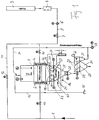
- Dust-laden, hot raw gas is fed to the system through a line (1).
- the raw gas comes, for example, from a drying plant for agricultural products, for example grass. It can also come from a sewage sludge incinerator.
- the temperature of the gas is typically 250 o C, but can rise to about 500 o C.
- the line (1) is connected to a raw gas hood (2) of a filter chamber (3).
- the filter chamber (3) is filled with a heat-resistant, abrasion-resistant granulate.
- the granules have a grain size of about 3 mm to 8 mm.
- broken calcium carbonate, washed gravel, basalt gravel or ceramic bodies can be used as granules. These can take the form of cubes, tetrahedra, cylinders or spheres, for example.
- a clean gas hood (4) is arranged on the filter chamber (3), which leads the dedusted gas into a line (5).
- a suction fan (6) is arranged in the line (5) and sucks the gas through the filter chamber (3) by means of negative pressure.
- a control valve (7) is arranged in the line (5).
- the line (5) opens into a chimney (9) via a silencer (8).
- Shut-off valves (10) are provided on both sides of the filter chamber (3).
- the shut-off valves (10) are open and the shut-off valve (12) is closed.
- the filter chamber (3) can be switched off by closing the shut-off valves (10) in the event of maintenance or malfunctions.
- the shut-off valve (12) is then opened, whereby however the raw gas reaches the chimney (9) without dedusting it.
- a silo (13) is arranged above the filter chamber (3) and contains granules and ensures that the filter chamber (3) is always completely filled with granules during filter operation. If the filter chamber (3) partially contained no granulate, then partial flows of the raw gas could get directly from the raw gas hood (2) into the clean gas hood (4) and would then exit without dedusting.
- a line (14) opens into the silo (13) through which granulate can be refilled into the silo (13).
- Two fill level meters (SL, SV) are arranged in the silo (13). If the level of the granulate in the silo (13) drops to the fill level meter (SL), then a pneumatic conveying device (15) delivers granulate through the line (14) until the upper fill level meter (SV) responds and the conveying device (15) switches off.
- outlet openings (17 to 20) are evenly distributed.
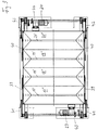
- four slot-shaped (see FIG. 3) outlet openings (17 to 20) are provided.
- Each of the outlet openings (17 to 20) tapers downwards in a funnel shape, the funnel shapes of adjacent outlet openings directly adjoining one another so that essentially the entire cross section of the bottom (16) or the filter chamber (3) into the outlet openings (17 to 20) leads.
- a closure member (21 or 22) is provided at each outlet opening (17 to 20).
- the closure members (21) of the two outlet openings (17, 18) are mechanically coupled to one another and can be actuated by means of a motor (23).
- the closure members (22) of the two outlet openings (19, 20) are also mechanically coupled to one another and can be driven by means of a further motor (24).
- the outlet openings (17 to 20) open at the bottom into a common discharge funnel (25).
- a lower level meter (AL) and an upper level meter (AV) are provided.
- the discharge funnel (25) opens into a lock (26) which leads into an aggregate (27) which separates the dust from the dust-laden granulate.
- it is a screening or brushing machine with motor-driven Beaters (28) and a sieve plate (29) through which the dust separated from the granulate reaches a collector (30). Dry cleaning of the granulate from the dust is cheap because no water is required.
- a connection chamber (31) for dedusted granules is connected to the unit (27).
- a traffic jam measuring device (32) is arranged, which switches off the aggregate (27) in the event of a traffic jam.
- a pneumatic return conveyor (33) is connected to the receiving chamber (31) and conveys dedusted granulate upwards into the silo (13) via a line (34).
- a differential pressure measuring device (35) is connected on the one hand to the raw gas hood (2) and on the other hand to the clean gas hood (4).
- the resulting differential pressure is a measure of the dust loading of the granules in the filter chamber (3). If the differential pressure reaches an upper limit value, the closure members (21 or 22) are opened alternately, but not simultaneously.
- the cleaned granulate is brought into the silo (13) by means of the return conveyor (33).
- the drives (23, 24) of the closure members (21 or 22) are released so that the closure members (21 or 22) open can be. This opening does not have to take place immediately afterwards, but takes place after a delay time or when there is a corresponding dust loading of the granules in the filter chamber (3).
- the dedusting process runs essentially as follows:
- the dust-laden exhaust gas is sucked through the granulate in the filter chamber (3).
- the dust accumulates on the granulate.
- either the closure members (21) by means of the motor (23) or the closure members (22) by means of the motor (24) are first brought out of their closed position into their open position.
- the closure members (21 or 22) are brought into their open position, dust-laden granulate emerges from a sub-zone of the total volume of the filter chamber (3). The granules of this sub-zone thus move downward into the discharge hopper (25) under the action of gravity.
- the filter chamber (3) and the discharge funnel (25) are thermally insulated to avoid condensation that could lead to caking of the dust-laden granulate.
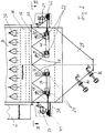
- FIGS. 2 and 3 show the structure of the filter chamber (3) in its area merging into the discharge funnel (25).
- FIG. 2 shows a gas channel (36) in the lower level and the gas channels (37) in the next upper level.
- the gas channels (36) are open to the raw gas hood (2).
- the gas channels (37) are open to the clean gas hood (4).
- the granulate is located between the gas channels (36, 37). The raw gas entering the gas channels (36) leaves them downward, passes through the granulate and enters the gas channels (37) in a dust-free manner below and enters the clean gas hood (4) from these gas channels (37).
- the closure members (21, 22) are formed by chutes. These are pivotally mounted on pendulum axles (38) from their open position to their closed position.
- the chutes are mechanically coupled to one another in groups, especially in pairs, using brackets (39, 40).
- the brackets (39 and 40) are driven by eccentric gears (41 and 42) which are connected to the motors (23 and 24).
- De-switches (43, 44) switch off the motors (23, 24) in the closed or open position.
- the outlet openings (17 to 20) form outlet slots (17 ', 18', 19 ', 20') adjacent to the chutes, which essentially extend over the entire width of the filter chamber (3) (cf. FIG. 3).
- the bottom (16) is tapered into funnel shapes (17 '' to 20 '') into the outlet slots (17 'to 20').
- the lowest gas channels (36) in the filter chamber (3) extend in their longitudinal direction transverse to the longitudinal direction of the outlet slots (17 'to 20').
- closure members (22) or chutes are shown in their open position.
- the closure members (21) or chutes are shown in their closed position.
- the outlet slots (19 ', 20') are open, so that dust-laden granulate emerges downward from the sub-zone of the filter chamber (3) above them, whereas in the sub-zone above the outlet slots closed by the closure members (21, 22) (17 ', 18') the granules stand still.
- each group of the closure members being driven by its own motor. It would be also possible to drive each closure member with its own motor and then control the motors so that only individual or a group of closure members is opened.
- all the closure members (21, 22) are in their closed position for a longer period.
- a single motor can be sufficient to drive all of the closure members.
Landscapes
- Chemical & Material Sciences (AREA)
- Chemical Kinetics & Catalysis (AREA)
- Filtering Of Dispersed Particles In Gases (AREA)
Applications Claiming Priority (2)
| Application Number | Priority Date | Filing Date | Title |
|---|---|---|---|
| DE19914135331 DE4135331C2 (de) | 1991-10-28 | 1991-10-28 | Verfahren zur Filterung von staubbeladenen Gasen und Staubfiltereinrichtung |
| DE4135331 | 1991-10-28 |
Publications (2)
| Publication Number | Publication Date |
|---|---|
| EP0539730A2 true EP0539730A2 (fr) | 1993-05-05 |
| EP0539730A3 EP0539730A3 (en) | 1993-05-19 |
Family
ID=6443466
Family Applications (1)
| Application Number | Title | Priority Date | Filing Date |
|---|---|---|---|
| EP19920116384 Withdrawn EP0539730A3 (en) | 1991-10-28 | 1992-09-24 | Process and apparatus for filtering dust |
Country Status (2)
| Country | Link |
|---|---|
| EP (1) | EP0539730A3 (fr) |
| DE (1) | DE4135331C2 (fr) |
Cited By (2)
| Publication number | Priority date | Publication date | Assignee | Title |
|---|---|---|---|---|
| CN108840064A (zh) * | 2018-08-23 | 2018-11-20 | 中冶赛迪工程技术股份有限公司 | 一种连续运行的清料装置及胶带机 |
| CN110090511A (zh) * | 2019-06-12 | 2019-08-06 | 中冶北方(大连)工程技术有限公司 | 用于活性焦烟气净化吸附单元的在线清灰系统 |
Family Cites Families (5)
| Publication number | Priority date | Publication date | Assignee | Title |
|---|---|---|---|---|
| US4601736A (en) * | 1984-11-06 | 1986-07-22 | Kabushikigaisha Takuma | Dynamic gas filter apparatus |
| DE3611953A1 (de) * | 1985-11-09 | 1987-08-13 | Kraftwerk Union Ag | Einrichtung zum gesteuerten abzug von fliessfaehigem schuettgut an der unterseite einer schuettgutsaeule, insbesondere eines wanderbettfilters |
| DE3712649C1 (en) * | 1987-04-14 | 1988-06-09 | Rudolf Ohlmann | Adsorber |
| DE3743561A1 (de) * | 1987-12-22 | 1989-07-06 | Deilmann Ag C | Verfahren und vorrichtung zum abscheiden von staub aus heissgasen |
| DE8901315U1 (de) * | 1989-02-06 | 1989-04-06 | Lufttechnik Bayreuth Rüskamp GmbH, 8580 Bayreuth | Austragseinrichtung für das Filtermaterial in einem Luftfilter |
-
1991
- 1991-10-28 DE DE19914135331 patent/DE4135331C2/de not_active Expired - Fee Related
-
1992
- 1992-09-24 EP EP19920116384 patent/EP0539730A3/de not_active Withdrawn
Cited By (2)
| Publication number | Priority date | Publication date | Assignee | Title |
|---|---|---|---|---|
| CN108840064A (zh) * | 2018-08-23 | 2018-11-20 | 中冶赛迪工程技术股份有限公司 | 一种连续运行的清料装置及胶带机 |
| CN110090511A (zh) * | 2019-06-12 | 2019-08-06 | 中冶北方(大连)工程技术有限公司 | 用于活性焦烟气净化吸附单元的在线清灰系统 |
Also Published As
| Publication number | Publication date |
|---|---|
| DE4135331A1 (de) | 1993-04-29 |
| DE4135331C2 (de) | 1996-02-15 |
| EP0539730A3 (en) | 1993-05-19 |
Similar Documents
| Publication | Publication Date | Title |
|---|---|---|
| DE69024699T2 (de) | Luftfilter mit horizontal angeordneten Filterelementen | |
| DE2738118C3 (de) | Filternder Abscheider mit Staubrückführung | |
| DE2402687A1 (de) | Staubfilter | |
| DE3012911A1 (de) | Vorrichtung zur regenerierenden reinigung eines aus koernigem material bestehenden filterbettes | |
| DE3507303A1 (de) | Anlage zur aufbereitung und reinigung verunreinigter gase | |
| EP0354952B1 (fr) | Cuve a lit mouvant de matiere coulante | |
| DE2738119C3 (de) | Schlauch- oder Taschenfilter | |
| DE3108175A1 (de) | Einrichtung und verfahren zum abtennen von in einem gasstrom mitgefuehrten feinteiligen feststoffen | |
| DE4002462A1 (de) | Verfahren und vorrichtung zum entfernen von schadstoffen aus rauch- und abgasen mit integriertem waermetauschersystem | |
| DE1461386C3 (de) | Filtervorrichtung zum Reinigen von Flüssigkeiten | |
| DE2344470A1 (de) | Filtervorrichtung mit abfuehrsystem | |
| DE9090200U1 (de) | Schüttgutreaktor | |
| DE2935773C2 (fr) | ||
| DE3443832C2 (de) | Schüttschichtfilter, insbesondere für Rauchgase | |
| EP0539730A2 (fr) | Procédé et dispositif pour la filtration de poussières | |
| DE3743561C2 (fr) | ||
| DE3305585C2 (de) | Filteranlage zum Reinigen von heißen Rohgasen | |
| DE339626C (de) | Verfahren und Vorrichtung zum Abscheiden fester Beimengungen aus Gasen auf trockenemWege | |
| DE3939645C3 (de) | Staubabscheider mit schlauchförmigen Filterelementen und Verfahren zum Wechseln derselben | |
| DE597188C (de) | Vorrichtung zum Brennen von Zement und aehnlichem Gut, bestehend aus einem zum Fertigbrennen dienenden Sinterofen, der mit einer Vorrichtung zur Vorbehandlung des Gutes mittels der Ofenabgase versehen ist | |
| AT130359B (de) | Verfahren zum Brennen von Zement und ähnlichem Gut in einem zum Fertigbrennen dienenden Sinterofen. | |
| DE3440145A1 (de) | Verfahren und vorrichtung zum entstauben von gas durch in schichten angeordnete granulatschuettungen | |
| DE102018125711A1 (de) | Verfahren und Vorrichtung zum Betrieb einer Trocknungsanlage für feuchtes Holz und dergleichen mit verbesserter Abgasqualität | |
| DE651128C (de) | Verfahren und Einrichtung zur Entleerung von Gasreinigern | |
| DE2923779A1 (de) | Austragstrichter fuer staubfilter |
Legal Events
| Date | Code | Title | Description |
|---|---|---|---|
| PUAI | Public reference made under article 153(3) epc to a published international application that has entered the european phase |
Free format text: ORIGINAL CODE: 0009012 |
|
| PUAL | Search report despatched |
Free format text: ORIGINAL CODE: 0009013 |
|
| AK | Designated contracting states |
Kind code of ref document: A2 Designated state(s): AT BE CH DE DK FR GB LI NL |
|
| AK | Designated contracting states |
Kind code of ref document: A3 Designated state(s): AT BE CH DE DK FR GB LI NL |
|
| RAP1 | Party data changed (applicant data changed or rights of an application transferred) |
Owner name: JUENGST, DIETER |
|
| 18D | Application deemed to be withdrawn |
Effective date: 19931120 |