EP0539733A1 - Siège, en particulier siège de bureau rotatif - Google Patents
Siège, en particulier siège de bureau rotatif Download PDFInfo
- Publication number
- EP0539733A1 EP0539733A1 EP92116447A EP92116447A EP0539733A1 EP 0539733 A1 EP0539733 A1 EP 0539733A1 EP 92116447 A EP92116447 A EP 92116447A EP 92116447 A EP92116447 A EP 92116447A EP 0539733 A1 EP0539733 A1 EP 0539733A1
- Authority
- EP
- European Patent Office
- Prior art keywords
- support
- seat part
- guide
- backrest
- chair
- Prior art date
- Legal status (The legal status is an assumption and is not a legal conclusion. Google has not performed a legal analysis and makes no representation as to the accuracy of the status listed.)
- Granted
Links
Images


Classifications
-
- A—HUMAN NECESSITIES
- A47—FURNITURE; DOMESTIC ARTICLES OR APPLIANCES; COFFEE MILLS; SPICE MILLS; SUCTION CLEANERS IN GENERAL
- A47C—CHAIRS; SOFAS; BEDS
- A47C1/00—Chairs adapted for special purposes
- A47C1/02—Reclining or easy chairs
- A47C1/031—Reclining or easy chairs having coupled concurrently adjustable supporting parts
- A47C1/032—Reclining or easy chairs having coupled concurrently adjustable supporting parts the parts being movably-coupled seat and back-rest
- A47C1/03294—Reclining or easy chairs having coupled concurrently adjustable supporting parts the parts being movably-coupled seat and back-rest slidingly movable in the base frame, e.g. by rollers
-
- A—HUMAN NECESSITIES
- A47—FURNITURE; DOMESTIC ARTICLES OR APPLIANCES; COFFEE MILLS; SPICE MILLS; SUCTION CLEANERS IN GENERAL
- A47C—CHAIRS; SOFAS; BEDS
- A47C1/00—Chairs adapted for special purposes
- A47C1/02—Reclining or easy chairs
- A47C1/031—Reclining or easy chairs having coupled concurrently adjustable supporting parts
- A47C1/032—Reclining or easy chairs having coupled concurrently adjustable supporting parts the parts being movably-coupled seat and back-rest
- A47C1/03205—Reclining or easy chairs having coupled concurrently adjustable supporting parts the parts being movably-coupled seat and back-rest having adjustable and lockable inclination
- A47C1/03233—Reclining or easy chairs having coupled concurrently adjustable supporting parts the parts being movably-coupled seat and back-rest having adjustable and lockable inclination by means of a rack-and-pinion or like gearing mechanism
-
- A—HUMAN NECESSITIES
- A47—FURNITURE; DOMESTIC ARTICLES OR APPLIANCES; COFFEE MILLS; SPICE MILLS; SUCTION CLEANERS IN GENERAL
- A47C—CHAIRS; SOFAS; BEDS
- A47C1/00—Chairs adapted for special purposes
- A47C1/02—Reclining or easy chairs
- A47C1/031—Reclining or easy chairs having coupled concurrently adjustable supporting parts
- A47C1/032—Reclining or easy chairs having coupled concurrently adjustable supporting parts the parts being movably-coupled seat and back-rest
- A47C1/03255—Reclining or easy chairs having coupled concurrently adjustable supporting parts the parts being movably-coupled seat and back-rest with a central column, e.g. rocking office chairs
-
- A—HUMAN NECESSITIES
- A47—FURNITURE; DOMESTIC ARTICLES OR APPLIANCES; COFFEE MILLS; SPICE MILLS; SUCTION CLEANERS IN GENERAL
- A47C—CHAIRS; SOFAS; BEDS
- A47C1/00—Chairs adapted for special purposes
- A47C1/02—Reclining or easy chairs
- A47C1/031—Reclining or easy chairs having coupled concurrently adjustable supporting parts
- A47C1/032—Reclining or easy chairs having coupled concurrently adjustable supporting parts the parts being movably-coupled seat and back-rest
- A47C1/03261—Reclining or easy chairs having coupled concurrently adjustable supporting parts the parts being movably-coupled seat and back-rest characterised by elastic means
- A47C1/03266—Reclining or easy chairs having coupled concurrently adjustable supporting parts the parts being movably-coupled seat and back-rest characterised by elastic means with adjustable elasticity
-
- A—HUMAN NECESSITIES
- A47—FURNITURE; DOMESTIC ARTICLES OR APPLIANCES; COFFEE MILLS; SPICE MILLS; SUCTION CLEANERS IN GENERAL
- A47C—CHAIRS; SOFAS; BEDS
- A47C1/00—Chairs adapted for special purposes
- A47C1/02—Reclining or easy chairs
- A47C1/031—Reclining or easy chairs having coupled concurrently adjustable supporting parts
- A47C1/032—Reclining or easy chairs having coupled concurrently adjustable supporting parts the parts being movably-coupled seat and back-rest
- A47C1/03261—Reclining or easy chairs having coupled concurrently adjustable supporting parts the parts being movably-coupled seat and back-rest characterised by elastic means
- A47C1/03272—Reclining or easy chairs having coupled concurrently adjustable supporting parts the parts being movably-coupled seat and back-rest characterised by elastic means with coil springs
Definitions
- the invention relates to a chair, in particular an office swivel chair according to the preamble of claim 1.
- Such a chair is known from DE-OS 39 30 983, in which the seat part support is moved forward and downward in a synchronous movement and the backrest support is inclined. The movement takes place via synchronous levers, which require a complex construction.
- Backrest support and seat part support are also connected to one another via a swivel axis, so that the two parts cannot be moved independently of one another.
- the relative movement between the backrest and the seat part which promotes the shirt pull-out effect, is largely reduced by the synchronizing lever provided with several articulation points, it cannot be completely eliminated due to the connection of the two carriers.
- a chair is also known in which an L-shaped backrest support is transferred in two guides from a working position to a rest position.
- the upper end of the backrest support moves downward and at the same time the seat part support connected to the backrest support directly via a pivot axis is moved forward and slightly downward in the rear part.
- the seat part support is undesirably raised at the front due to the arrangement of the front guide of the backrest support required for the tilting movement.
- Due to its L-shape the backrest support is tilted into two guides, which then still allow movement about an imaginary axis, but which due to the large radius specified by the guides is largely stationary at chest or stomach height and a short distance from the seat user .
- the backrest support and seat support have a common swivel axis, independent movement of both elements is not possible.
- the invention has for its object to develop a chair of the type mentioned in such a way that an aesthetically sophisticated chair is realized in a cost-effective manner, which allows the transfer to a comfortable rest position as possible.
- the required comfort of a chair is determined by how far the backrest can be tilted backwards.
- the relation of backrest / seat pressure in case of induced load changes during "dynamic sitting" can be considered a comfort-determining factor.
- this maximum possible inclination is fundamentally limited by the permissible projection of the backrest, since if the backrest is inclined without simultaneously moving the seat part carrier forward, the center of gravity is moved so far away from the axis of rotation that there is an increased risk of tipping.
- the center of gravity is now shifted forward when the backrest inclination is adjusted by the forward movement of the seat part carrier, so that even greater inclinations can be realized safely without the need for cantilevered outriggers for support at the foot of the chair.
- the seat part carrier is moved independently of the backrest carrier, so that the undesired lifting of the support zone of the thighs is avoided. Rather, the prerequisites for an ergonomic principle following horizontal movement of the front edge of the seat, which remains at almost the same height, are created.
- the shirt pull-out effect which causes a seat user to take off his shirt when he tilts the backrest part backwards with the aid of a body motor and thereby leans with his back against the backrest, is based on a relative movement between the backrest and the back of the user, in which usually the backrest moves upward relative to the user's back.
- the backrest support will now not only reduced this relative movement to zero, but rather also lowered the backrest support more than the seat part support, so that, in contrast to known chairs, the backrest support now moves downwards relative to the back of the user, i.e. the shirt is put on him.
- the seat part carrier is moved on a separate path regardless of the circular movement of the backrest carrier.
- the sagging of the backrest support occurring under circular guides of the backrest support can be counteracted, so that apart from the body movement of the user hardly any aids are required for transferring to the two end positions.
- a guide along an arch is to be understood to mean a guide that either has arch-shaped elements on the backrest support that are moved along stationary bearings of the frame, or that on Backrest support has bearings that are moved in arcuate guides of the frame, regardless of whether the arc is a circular arc or the section of a hyperbola, parabola or a similarly curved section of a geometric line.
- the axis about which at least the backrest support moves is arranged at the level of the imaginary axis between the hip joints of the user, then a relative movement between the person and the chair is reduced.
- a roller can be used for permanent guidance on a career in that this roller rolls along its circumference to reduce friction only at small points. If the roller moves out of its centered position, the outwardly decreasing diameter leads to self-centering, since the larger diameter that occurs during a lateral movement tends to reset itself like rollers on appropriately shaped railroad tracks. If the track is designed accordingly, an increased relative movement between the seat part carrier and the backrest carrier is produced during the initial transfer movement from the working position.
- a band or rope is provided as a connecting means between the backrest support and the seat part support, which is also connected to the frame. In combination with the running track, an optimal transfer movement can be achieved and the belt can still be held in any position.
- an axis is provided at the stationary point of the frame, which can influence and coordinate the desired relative movements between the backrest support and seat part support by appropriate shaping.
- a connecting element windable tapes, ropes or the like can be used. Due to the stretching characteristic, a rope is preferably wound on a part of the axis during the transfer movement and unwound on the other part of the axis.
- two ropes and two different axes can also be used.
- the axle also serves as a guide roller for the seat support, which ensures the drive of the axle.
- a single rope can be used, which is simply inserted in the axis through a central bore with radial access openings on one side of the bore and exits on the other side of the bore.
- the pictures show the chair, which is preferably used as an office swivel chair in three exemplary embodiments.
- the reference numerals of the second and third exemplary embodiments are distinguished from the first exemplary embodiment in that, in the case of corresponding parts, a 1 is given in front with respect to the reference numerals or 2 is set in advance, ie they are increased by 100 or 200 compared to the first embodiment.
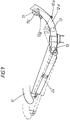
- All of the exemplary embodiments have in common that a seat part support 11, 111, 211 and a backrest support 12, 112, 12 which is adjustable in inclination are movably connected to the frame 10, 110, 210 in a synchronous adjustment movement relative to the frame.
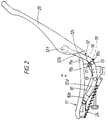
- the backrest support engages under the seat part support.
- the upper part 12b, 112b, 212b of the backrest support 12, 112, 212 is lowered.
- Seat part carrier 11, 111, 211 and backrest carrier 12, 112, 212 are connected to one another by means of a connecting element in such a way that when the transfer movement into the rest position, the backrest carrier in the connection area 12c, 112c, 212c to the seat part carrier is at least slightly more lowered than that at the same time forward and in the rear part 11b, 111b, 211b seat part carriers moved downwards.
- the backrest support and seat support support transmit their movement to one another and to a connecting element by being connected to it at two spaced apart points, so that they can move on two mutually independent tracks.
- the backrest support is guided under an arch under the seat part support, the transfer movement achieved thereby taking place approximately around an imaginary axis M at the level of the user's hip joints.
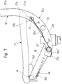
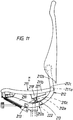
- the seat part carrier 11, 111, 211 basically moves forward (FIG. 3).
- this movement takes place below a horizontal plane hh, which is determined by the highest point P of the seat part carrier in its working position.
- a guide pin or a guide roller 14, 114 is provided on the frame 10, 110, on which the seat part carrier 11, 111, 211 is guided with an elongated hole guide 11d, 111d.
- this principle can also be reversed, i.e. with an elongated hole guide on the frame, which is inclined forward to avoid raising the front edge of the seat.
- the elongated hole guide 11d slides past the guide roller with a change in inclination.
- the seat part carrier 11 can also be articulated on the frame 10 via at least one pendulum support, each with a joint assigned to the frame and the seat part carrier, which should already be inclined forward in the working position.
- the backrest support 12 merges from an arch arranged at the bottom (guides 12d) into the upper, almost straight part 12b, on which the backrest 25 is articulated on the joint 12f, 112f.
- the backrest support 12 has at its lower end 12a at least one circular-shaped guide 12d which is guided on at least two bearings 13 arranged in a stationary manner on the frame 10.
- the radius of the circular arc enables movement around the imaginary axis.
- the seat part support 11 moves on a path that is independent of the backrest support.
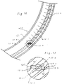
- the seat part support 11 has at its rear end 11b at least one roller 17 which rolls on the track designed as a track 18.
- the schematic FIG. 6 shows the self-centering principle of the symmetrical roller 17, which is guided on an axis 11c of the seat part carrier 11.
- the track 18 provided on the frame 10 has a central recess groove 18a into which the roller is immersed with a central radial rib 17a.
- the roller is designed in the form of a roller, its diameter decreasing linearly outwards, starting from the radial rib 17a, which has the largest diameter of the roller 17.
- the track 18 is wave-shaped (Fig. 4.5). Starting from the position of the roller 17 in the rest position, it is initially convex and then concave when it is transferred to the working position. This initially provides resistance to the chair's initial effort to sag along the arch under load. However, this also leads to an increased relative movement between the seat part support and the backrest support, especially at the start of the transfer movement, which even slips on the shirt of the user.
- the backrest support 12, the seat part support 11 and the frame 10 are connected to one another via a rope or band 19 which is fastened to the backrest support 12 in the region of the curved guides 12d and to the rear edge 10c of the frame 10.
- a rope or band 19 which is fastened to the backrest support 12 in the region of the curved guides 12d and to the rear edge 10c of the frame 10.
- the indirect connection of seat support 11 and backrest support 12 with a band requires that the band is always kept under tension, which is ensured by appropriate training of the track 18 in all positions of the chair.
- a greater or lesser disproportionate pivoting of the backrest support is achieved.
- the belt at least partially wraps around the axis 11c fastened to the seat part carrier 11 clockwise or counterclockwise, which allows a further possibility of fine adjustment of the adjustment possibilities.
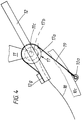
- FIGS. 7 and 8 show a further connection with a cable 19 'which is connected to the backrest support 12 at a pivot point 12g via a front section 19b'.
- the rope is connected to the seat part carrier 11 by a rear section 19a ′ at the articulation point 17d of an axis 17c of the guide roller 17.
- the connection to the frame 10 takes place via an axis 15 ′ which is fixed to the frame 10 and carries a roller corresponding to the guide roller 13, at least with regard to its diameter.
- the two parts 19a ', 19b' of the rope 19 ' are connected to this axis.
- the axis 15 ' has an inner section 15a' which lies outside the guide rail of the circular guide 12d of the backrest support and an outer section 15b 'which lies within the circular guide 12d.
- On the inner section 15a ' the part 19a' of the rope 19 'assigned to the seat part carrier 11 is wound up or unwound, while on the outer section 15b' the front part 19b 'of the rope 19' is unwound or unwound at the same time.
- the axis 15 'mounted on the frame 10 has a central bore 15e' which is accessible via radial access openings 15c ', 15d'. This hole allows only one rope to be used to link all three parts. During production, the rope is inserted through one opening 15d 'and exits through the hole 15e' from the other opening 15c '. When making the hole the axis is drilled from one side and then the radial holes are made.
- the axle with its inner section 15a 'is mounted on the frame then the backrest support is attached to the axle sections 15' and the guide roller 13, and the outer section 15b 'is then fastened to the axle by threaded connections. If the axis 15 'also represents a guide roller 13 for the circular-shaped guides 12d of the backrest support 12 (FIG. 7), the backrest support can simultaneously drive the stationary axis and thus move the seat part support.
- the seat part carrier 111 is arranged in the rear part 111b on at least one lever 116 which is articulated on the frame 110 and which is articulated on the joint 111c on the seat part carrier and which is actuated by the backrest carrier 112.
- the backrest support 112 is connected to the seat part support via a connecting element and has at its lower end 112a an actuation profile 115 which engages on a guide 120 of the lever 116.
- the lever which is initially slightly inclined forward is actuated by the lowering backrest support 112, the forward movement of the seat part support being initiated.
- the molded on the backrest support profile presses on the guide designed as a guide roller, so that the two parts roll on each other.
- a separate lowering of the seat part carrier can be achieved, so that the profile e.g. career 18 can be mimicked.
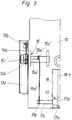
- the backrest support 212 and the seat support 211 are assigned racks 211f, 212e, which mesh with at least one gear 221,222. Either two gears with different sprockets are used, as shown, or the distance between the teeth of the respectively assigned gear and rack is differentiated, so that here too the disproportionate pivoting is realized.
- the seat part carrier 11 can also be guided only at the front end 10b of the frame 10 in two guides which absorb the load on the seat part carrier 11 and which bring about the desired movement independent of the backrest carrier.
- An indirect connection via an elastic spring, preferably a metal tongue, is also possible, which is dimensioned for a sufficient number of load cycles and allows a separate transfer of the seat part carrier.
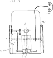
- the chair can easily be kept in balance in any position, particularly in the case of an embodiment according to the first exemplary embodiment, there is nevertheless the possibility of moving the transfer movement into the rest position against the force of a (compression or tension) spring 24 or a gas spring 24 ' (Fig. 9) perform, which engages the frame 10 and the front end of the seat support 11.
- a (compression or tension) spring 24 or a gas spring 24 ' Fig. 9
- the maximum pivoting angle ⁇ of the backrest support between the rest position and the working position is approximately 2.5 times as large as the angle of inclination ⁇ of the seat part support 11, 111, 211 that occurs.
- recesses 12h spaced apart from one another in the guide direction can be provided in the guides, preferably guide 12d or slot guide 11d of the seat part carrier.
- An adjusting member 27 can be pivoted into these recesses and can be pivoted about an adjusting axis which is arranged transversely to the guide rail and plunges into the latter. The position of the adjusting member 27 changes during the transfer movement relative to the guides, so that a latching in the recesses 12h is possible due to the pivoting movement of the adjusting member.
- the adjustment axis 26 of the adjustment member 27 is mounted on the frame 10 in a stationary manner and the backrest support 12 has the circular-shaped guide 12d with the recesses 12h.
- the adjustment axis 26 extends through either the guide slot already formed by the mounting of the guide rollers 13 or a separate guide slot 12k.
- the recesses can either be arranged on the walls 12 l of the guide 12d or on the base 12m of the guide. In the latter case, the guide reason is also used as a grid adjustment.
- the mutually offset recesses are arranged on both sides of the guide slot at regular intervals and are each at a diagonal distance which corresponds to the length of the adjusting member 27 with its two pivot arms 27a. In the non-operative position, the adjusting member 27 can be arranged approximately parallel to the walls of the guide slot 12k, so that the adjusting member "slides" in the guide slot 12k.
- the pivot arms 27a rest in the locking position on a side surface 27b on a flank 12h of the recesses.
- the actual locking takes place, as can be seen from FIG. 3, by abutting the end faces 27c of the swivel arms 27a on the respective other flank 12h ′′ of the recesses 12h.
- a pivoting movement of approximately 45 ° takes place, the rectangular pivot arms 27a being driven into the triangular recesses 12h.
- the pivoting movement is triggered by a lever 28, which is located under the seat of the chair.
- This lever is under the force of a spring so that it is automatically returned to the locking position. However, it can also be locked out of the active position.
Landscapes
- Health & Medical Sciences (AREA)
- Dentistry (AREA)
- General Health & Medical Sciences (AREA)
- Chairs For Special Purposes, Such As Reclining Chairs (AREA)
- Chairs Characterized By Structure (AREA)
- Chair Legs, Seat Parts, And Backrests (AREA)
- Special Chairs (AREA)
Applications Claiming Priority (4)
| Application Number | Priority Date | Filing Date | Title |
|---|---|---|---|
| DE4135948 | 1991-10-31 | ||
| DE4135948A DE4135948C2 (de) | 1991-10-31 | 1991-10-31 | Stuhl, insbesondere Bürodrehstuhl |
| DE4208227 | 1992-03-14 | ||
| DE4208227A DE4208227A1 (de) | 1991-10-31 | 1992-03-14 | Stuhl, insbesondere buerodrehstuhl |
Publications (2)
| Publication Number | Publication Date |
|---|---|
| EP0539733A1 true EP0539733A1 (fr) | 1993-05-05 |
| EP0539733B1 EP0539733B1 (fr) | 1995-12-06 |
Family
ID=25908700
Family Applications (1)
| Application Number | Title | Priority Date | Filing Date |
|---|---|---|---|
| EP92116447A Expired - Lifetime EP0539733B1 (fr) | 1991-10-31 | 1992-09-25 | Siège, en particulier siège de bureau rotatif |
Country Status (13)
| Country | Link |
|---|---|
| US (1) | US5354120A (fr) |
| EP (1) | EP0539733B1 (fr) |
| JP (1) | JPH05211927A (fr) |
| CN (1) | CN1074361A (fr) |
| AT (1) | ATE131017T1 (fr) |
| CA (1) | CA2079644A1 (fr) |
| CZ (1) | CZ321692A3 (fr) |
| DE (3) | DE4135948C2 (fr) |
| HU (1) | HUT63040A (fr) |
| LT (1) | LT3458B (fr) |
| PL (1) | PL296407A1 (fr) |
| SK (1) | SK321692A3 (fr) |
| ZA (1) | ZA927678B (fr) |
Cited By (8)
| Publication number | Priority date | Publication date | Assignee | Title |
|---|---|---|---|---|
| EP0614633A1 (fr) * | 1993-02-25 | 1994-09-14 | Herman Miller, Inc. | Dossier réglable pour chaise |
| WO1996001581A3 (fr) * | 1994-07-08 | 1996-06-06 | Rolf Voelkle | Siege |
| WO1997022282A1 (fr) * | 1995-12-18 | 1997-06-26 | Peter Opsvik A.S | Dispositif de reglage de chaises |
| US5797653A (en) * | 1993-07-22 | 1998-08-25 | Dauphin Entwicklungs - U. Beteiligungs-Gmbh | Chair, in particular office chair |
| DE19502485C2 (de) * | 1995-01-27 | 1999-09-16 | Fus Rainer | Stuhl |
| US5971481A (en) * | 1996-10-11 | 1999-10-26 | Giroflex Entwicklungs Ag | Chair, specially an office chair |
| WO2002067726A1 (fr) * | 2001-02-28 | 2002-09-06 | Interstuhl Büromöbel GmbH & Co. KG | Siege, notamment siege de bureau |
| EP2896326A1 (fr) * | 2014-01-21 | 2015-07-22 | Stoll Giroflex AG | Siège, en particulier chaise |
Families Citing this family (98)
| Publication number | Priority date | Publication date | Assignee | Title |
|---|---|---|---|---|
| KR100334316B1 (ko) | 1992-06-15 | 2002-10-11 | 헤르만밀러인코퍼레이티드 | 사무용의자의지지장치및제조방법 |
| US5765914A (en) * | 1995-06-07 | 1998-06-16 | Herman Miller, Inc. | Chair with a tilt control mechanism |
| US5810439A (en) * | 1996-05-09 | 1998-09-22 | Haworth, Inc. | Forward-rearward tilt control for chair |
| US5871258A (en) * | 1997-10-24 | 1999-02-16 | Steelcase Inc. | Chair with novel seat construction |
| US6250715B1 (en) | 1998-01-21 | 2001-06-26 | Herman Miller, Inc. | Chair |
| ITVI980182A1 (it) * | 1998-09-25 | 2000-03-25 | Enrico Cioncada | Sedia ad assetto variabile. |
| DE29910620U1 (de) * | 1999-06-17 | 2000-10-19 | König + Neurath AG, 61184 Karben | Stuhl, insbesondere Bürostuhl |
| USD446397S1 (en) | 2000-09-28 | 2001-08-14 | Formway Furniture Limited | Chair |
| USD448277S1 (en) | 2000-09-28 | 2001-09-25 | Formway Furniture Limited | Castor |
| USD445580S1 (en) | 2000-09-28 | 2001-07-31 | Formway Furniture Limited | Chair |
| USD460300S1 (en) | 2000-09-28 | 2002-07-16 | Formway Furniture Limited | Slotted seat panel for a chair |
| AU783829B2 (en) | 2000-09-28 | 2005-12-08 | Formway Furniture Limited | A reclinable chair |
| USD463144S1 (en) | 2000-09-28 | 2002-09-24 | Formway Furniture Limited | Chair |
| USD448219S1 (en) | 2000-09-28 | 2001-09-25 | Formway Furniture Limited | Castored base for a chair |
| AUPR054400A0 (en) | 2000-09-29 | 2000-10-26 | Formway Furniture Limited | A castor |
| DE10152560A1 (de) | 2000-10-12 | 2003-05-08 | Sven Poppel | Stuhl |
| DE10122948C1 (de) * | 2001-05-11 | 2003-03-13 | Armin Sander | Stuhl, insbesondere Bürostuhl |
| DE10122946C1 (de) * | 2001-05-11 | 2003-01-30 | Armin Sander | Stuhl, insbesondere Bürostuhl |
| DE10126001A1 (de) * | 2001-05-18 | 2002-11-21 | Bock 1 Gmbh & Co | Vorgespannte Federanordnung, insbesondere zur Federbeaufschlagung von Synchronmechaniken von Bürostühlen |
| DE10125994A1 (de) * | 2001-05-18 | 2002-11-21 | Bock 1 Gmbh & Co | Synchronmechanik für eine korrelierte Sitz-Rückenlehnen-Bewegung eines Bürostuhles |
| US6585320B2 (en) | 2001-06-15 | 2003-07-01 | Virco Mgmt. Corporation | Tilt control mechanism for a tilt back chair |
| US6644741B2 (en) | 2001-09-20 | 2003-11-11 | Haworth, Inc. | Chair |
| DE20116683U1 (de) * | 2001-10-13 | 2002-01-24 | Völkle, Rolf, 72290 Loßburg | Sitzmöbel, insbesondere Bürodrehstuhl |
| US20030132653A1 (en) * | 2001-10-18 | 2003-07-17 | Doug Thole | Tension control mechanism for a chair |
| KR100434997B1 (ko) * | 2002-01-02 | 2004-06-09 | 주식회사 일룸 | 의자의 등받이 |
| ES2192476B2 (es) * | 2002-01-18 | 2004-06-01 | Sebastian Aramburu Echevarria | Sillon reclinable. |
| NZ518944A (en) | 2002-05-14 | 2004-09-24 | Formway Furniture Ltd | Height adjustable arm for chair with outer stem releasably lockable to inner stem by engagement of recesses |
| KR100474392B1 (ko) * | 2002-12-03 | 2005-03-10 | 주식회사 일룸 | 틸팅 가능 의자 |
| DE20306014U1 (de) * | 2003-04-14 | 2003-06-26 | Vitra Patente Ag, Muttenz | Mechanik für einen Stuhl mit einer Gasfeder zur synchronen Steuerung der Neigung von Sitz und Rückenlehne |
| DE10318759B3 (de) * | 2003-04-25 | 2004-07-29 | Armin Sander | Stuhl, insbesondere Bürostuhl, und modulares Stuhlkonzept |
| US7322653B2 (en) * | 2003-06-13 | 2008-01-29 | Vlad Dragusin | Integrated videogaming and computer workstation |
| US7207629B2 (en) * | 2003-06-23 | 2007-04-24 | Herman Miller, Inc. | Tilt chair |
| US6945602B2 (en) * | 2003-12-18 | 2005-09-20 | Haworth, Inc. | Tilt control mechanism for chair |
| US6969116B2 (en) * | 2003-12-30 | 2005-11-29 | Hni Technologies Inc. | Chair with backward and forward passive tilt capabilities |
| US8240771B2 (en) | 2004-05-13 | 2012-08-14 | Humanscale Corporation | Mesh chair component |
| US7458637B2 (en) | 2004-06-10 | 2008-12-02 | Steelcase Inc. | Back construction with flexible lumbar |
| US7237841B2 (en) | 2004-06-10 | 2007-07-03 | Steelcase Development Corporation | Back construction with flexible lumbar |
| HK1064859A2 (en) * | 2004-06-21 | 2005-01-14 | 田雨阳 | Synchronous coordinate system of back of chair |
| KR100499792B1 (ko) * | 2004-10-13 | 2005-07-07 | 이규윤 | 의자 |
| USD623449S1 (en) | 2005-05-13 | 2010-09-14 | Humanscale Corporation | Mesh backrest for a chair |
| AR057387A1 (es) * | 2005-06-20 | 2007-12-05 | Humanscale Corp | Aparato de asiento con movimiento reclinable |
| US20070222266A1 (en) * | 2006-03-21 | 2007-09-27 | Ditto Sales, Inc. | Nestable and stackable chair |
| USD661135S1 (en) | 2006-06-20 | 2012-06-05 | Humanscale Corporation | Pair of armrests for a chair or the like |
| EP1908374B1 (fr) * | 2006-10-06 | 2009-02-11 | Stoll Giroflex AG | Chaise de bureau synchrone |
| CN102772053A (zh) | 2007-01-29 | 2012-11-14 | 赫尔曼米勒有限公司 | 座位结构及其使用方法 |
| KR100968547B1 (ko) | 2008-03-27 | 2010-07-08 | 듀오백코리아 주식회사 | 의자의 틸팅 장치 |
| KR100968540B1 (ko) | 2008-03-27 | 2010-07-08 | 듀오백코리아 주식회사 | 의자의 슬라이딩 방식 틸팅 장치 |
| EP2252179B1 (fr) | 2008-05-26 | 2012-07-11 | Steelcase Inc. | Dossier souple de siège |
| KR20110022040A (ko) * | 2008-06-05 | 2011-03-04 | 가부시기가이샤 우찌다요우고우 | 기울임 가능한 등받이를 갖는 의자 |
| DE102009009287A1 (de) * | 2009-02-17 | 2010-09-09 | Uhlenbrock, Christel | Sitzmöbel, insbesondere Bürodrehstuhl |
| US8100478B2 (en) * | 2009-07-06 | 2012-01-24 | Honda Motor Co., Ltd. | Vehicle seat assembly |
| US9241571B2 (en) * | 2009-08-18 | 2016-01-26 | Integrated Furniture Technologies Limited | Adjustable furniture |
| PL2608700T3 (pl) * | 2010-08-25 | 2014-12-31 | L&P Property Man Co | Mechanizm odchylania dla fotela oraz fotel |
| US9364091B2 (en) * | 2010-08-25 | 2016-06-14 | L&P Property Management Company | Tilt mechanism for a chair and chair |
| JP5634890B2 (ja) * | 2011-01-17 | 2014-12-03 | カリモク家具株式会社 | 椅子 |
| US8556345B2 (en) * | 2011-03-14 | 2013-10-15 | Sheng Jia Sheng Co., Ltd. | Chair having angle and tension adjusting functions |
| JP2012249826A (ja) * | 2011-06-03 | 2012-12-20 | Takano Co Ltd | 椅子 |
| US9265348B2 (en) * | 2011-08-03 | 2016-02-23 | Haworth, Inc. | Adjusting mechanism for setting a restoring force which acts on a backrest of a chair, and office chair having an adjusting mechanism of this type |
| MX343649B (es) | 2011-09-21 | 2016-11-14 | Miller Herman Inc | Reposacabezas de dos niveles, estructura de soporte del cuerpo y método para soportar el cráneo de un usuario. |
| WO2013058538A1 (fr) * | 2011-10-21 | 2013-04-25 | Lee Jae Hyun | Siège de correction de posture utilisant un moyen à coulisse |
| KR101300678B1 (ko) | 2011-12-08 | 2013-08-27 | 한국생산기술연구원 | 의자용 슬라이드 틸팅 장치 및 이를 구비한 의자 |
| CN103355974B (zh) * | 2012-04-09 | 2016-04-13 | 周新 | 靠背在使用状态时可以锁定的倾仰式椅子框架 |
| US9504326B1 (en) | 2012-04-10 | 2016-11-29 | Humanscale Corporation | Reclining chair |
| PL2892390T3 (pl) * | 2012-09-05 | 2018-01-31 | Godrej & Boyce Mfg Co Ltd | Krzesło z regulowanym oparciem i siedzeniem |
| US9706845B2 (en) | 2012-09-20 | 2017-07-18 | Steelcase Inc. | Chair assembly |
| USD696545S1 (en) | 2013-07-30 | 2013-12-31 | Steelcase, Inc. | Rear surface of a chair back |
| CN106455821A (zh) | 2014-04-17 | 2017-02-22 | Hni技术公司 | 椅子和椅子控制组件、系统和方法 |
| CN203952966U (zh) * | 2014-06-26 | 2014-11-26 | 陈国巨 | 椅背后仰时坐垫前移并同时下降的椅子 |
| BR112017005243B1 (pt) | 2014-09-15 | 2023-01-10 | 3M Innovative Properties Company | Método e dispositivo para monitorar indicadores de disfunção |
| CA2961368A1 (fr) | 2014-09-15 | 2016-03-24 | 3M Innovative Properties Company | Detection de deficience |
| KR20220140018A (ko) | 2014-09-15 | 2022-10-17 | 쓰리엠 이노베이티브 프로퍼티즈 캄파니 | 환경 고려사항을 이용한 손상 검출 |
| DE102015102007B3 (de) * | 2015-02-12 | 2016-07-28 | Wilkhahn Wilkening + Hahne Gmbh + Co. | Sitzmöbel |
| US10194750B2 (en) | 2015-04-13 | 2019-02-05 | Steelcase Inc. | Seating arrangement |
| US10966527B2 (en) | 2017-06-09 | 2021-04-06 | Steelcase Inc. | Seating arrangement and method of construction |
| US10021984B2 (en) | 2015-04-13 | 2018-07-17 | Steelcase Inc. | Seating arrangement |
| US11259637B2 (en) | 2015-04-13 | 2022-03-01 | Steelcase Inc. | Seating arrangement |
| EP3108867B1 (fr) * | 2015-06-23 | 2018-12-05 | Cefla Societa' Cooperativa | Fauteuil dentaire |
| CN108601453B (zh) * | 2016-02-05 | 2021-11-05 | 佛姆维家具有限公司 | 椅子和部件 |
| CN106108444B (zh) * | 2016-08-23 | 2023-11-07 | 浙江博泰家具有限公司 | 一种用于可躺椅的框架结构 |
| US10231546B2 (en) | 2017-03-02 | 2019-03-19 | Knoll, Inc. | Chair back tilt mechanism |
| CN109484259B (zh) * | 2018-09-26 | 2020-08-25 | 盐城同环机电科技有限公司 | 一种车辆座椅靠背锁止装置 |
| USD936985S1 (en) | 2020-02-19 | 2021-11-30 | Steelcase Inc. | Chair |
| USD961317S1 (en) | 2020-02-19 | 2022-08-23 | Steelcase Inc. | Backrest |
| USD961281S1 (en) | 2020-02-19 | 2022-08-23 | Steelcase Inc. | Chair |
| USD935824S1 (en) | 2020-02-19 | 2021-11-16 | Steelcase Inc. | Seat |
| USD961280S1 (en) | 2020-02-19 | 2022-08-23 | Steelcase Inc. | Chair |
| USD937595S1 (en) | 2020-02-19 | 2021-12-07 | Steelcase Inc. | Chair |
| USD937024S1 (en) | 2020-02-19 | 2021-11-30 | Steelcase Inc. | Backrest |
| USD936984S1 (en) | 2020-02-19 | 2021-11-30 | Steelcase Inc. | Chair |
| DE102020110707A1 (de) | 2020-04-20 | 2021-10-21 | Bock 1 Gmbh & Co. Kg | Sitzmöbel |
| US11690455B2 (en) * | 2020-09-18 | 2023-07-04 | Dinkar Chellaram | Synchronous-tilt reclining chair |
| USD988048S1 (en) | 2021-01-20 | 2023-06-06 | Steelcase Inc. | Lumbar support |
| USD995179S1 (en) | 2021-01-20 | 2023-08-15 | Steelcase Inc. | Chair with lumbar support |
| USD988049S1 (en) | 2021-05-12 | 2023-06-06 | Steelcase Inc. | Lumbar support |
| USD995180S1 (en) | 2021-05-12 | 2023-08-15 | Steelcase Inc. | Chair with lumbar support |
| CN113729428B (zh) * | 2021-05-27 | 2025-06-27 | 广东联友办公家具有限公司 | 一种电控底盘及座椅 |
| CN113729426B (zh) * | 2021-05-27 | 2025-11-28 | 广东联友办公家具有限公司 | 一种座椅底盘及座椅 |
| US12414884B1 (en) * | 2021-06-04 | 2025-09-16 | Ki Mobility, LLC | Tiltable wheelchair |
Citations (5)
| Publication number | Priority date | Publication date | Assignee | Title |
|---|---|---|---|---|
| US3036862A (en) * | 1959-01-31 | 1962-05-29 | Stuttgarter Karosseriewerk Reu | Adjusting device for a folding back for a vehicle seat |
| DE2642091A1 (de) * | 1976-09-18 | 1978-03-23 | Wilde & Spieth | Buerostuhl |
| DE3530868A1 (de) * | 1985-08-29 | 1987-03-05 | Kusch Co Sitzmoebel | Wippmechanik fuer sitzmoebel |
| FR2627968A1 (fr) * | 1988-03-07 | 1989-09-08 | Eurosit | Siege articule |
| DE3930983A1 (de) * | 1989-09-16 | 1991-03-28 | Rolf Voelkle | Sitzmoebel mit neigungsverstellbarer sitzflaeche |
Family Cites Families (5)
| Publication number | Priority date | Publication date | Assignee | Title |
|---|---|---|---|---|
| DE2735522A1 (de) * | 1977-08-06 | 1979-02-15 | Wilde & Spieth | Buerostuhl |
| DE7815561U1 (fr) * | 1978-05-24 | 1978-09-14 | Martin Stoll Giroflex Gmbh, 7897 Tiengen | |
| FR2478982A1 (fr) * | 1980-03-26 | 1981-10-02 | Faure Bertrand | Perfectionnements aux sieges a dossier reglable en inclinaison |
| NO160896C (no) * | 1986-05-09 | 1989-06-14 | Jurek Buchacz | Stillbar sitteanordning. |
| ES2021653B3 (es) | 1987-08-14 | 1991-11-16 | Grammer Ag | Asiento, especialmente asiento de trabajo, o sea, silla de oficina o asiento de conductor |
-
1991
- 1991-10-31 DE DE4135948A patent/DE4135948C2/de not_active Expired - Fee Related
-
1992
- 1992-03-14 DE DE4208227A patent/DE4208227A1/de not_active Withdrawn
- 1992-09-25 EP EP92116447A patent/EP0539733B1/fr not_active Expired - Lifetime
- 1992-09-25 DE DE59204595T patent/DE59204595D1/de not_active Expired - Fee Related
- 1992-09-25 AT AT92116447T patent/ATE131017T1/de not_active IP Right Cessation
- 1992-10-01 CA CA002079644A patent/CA2079644A1/fr not_active Abandoned
- 1992-10-06 ZA ZA927678A patent/ZA927678B/xx unknown
- 1992-10-15 SK SK321692A patent/SK321692A3/sk unknown
- 1992-10-19 LT LTIP218A patent/LT3458B/lt not_active IP Right Cessation
- 1992-10-21 US US07/964,025 patent/US5354120A/en not_active Expired - Fee Related
- 1992-10-23 CZ CS923216A patent/CZ321692A3/cs unknown
- 1992-10-26 HU HU9203352A patent/HUT63040A/hu unknown
- 1992-10-26 CN CN92112423A patent/CN1074361A/zh active Pending
- 1992-10-29 PL PL29640792A patent/PL296407A1/xx unknown
- 1992-11-02 JP JP4317770A patent/JPH05211927A/ja not_active Withdrawn
Patent Citations (5)
| Publication number | Priority date | Publication date | Assignee | Title |
|---|---|---|---|---|
| US3036862A (en) * | 1959-01-31 | 1962-05-29 | Stuttgarter Karosseriewerk Reu | Adjusting device for a folding back for a vehicle seat |
| DE2642091A1 (de) * | 1976-09-18 | 1978-03-23 | Wilde & Spieth | Buerostuhl |
| DE3530868A1 (de) * | 1985-08-29 | 1987-03-05 | Kusch Co Sitzmoebel | Wippmechanik fuer sitzmoebel |
| FR2627968A1 (fr) * | 1988-03-07 | 1989-09-08 | Eurosit | Siege articule |
| DE3930983A1 (de) * | 1989-09-16 | 1991-03-28 | Rolf Voelkle | Sitzmoebel mit neigungsverstellbarer sitzflaeche |
Cited By (11)
| Publication number | Priority date | Publication date | Assignee | Title |
|---|---|---|---|---|
| EP0614633A1 (fr) * | 1993-02-25 | 1994-09-14 | Herman Miller, Inc. | Dossier réglable pour chaise |
| US5511852A (en) * | 1993-02-25 | 1996-04-30 | Herman Miller, Inc. | Adjustable backrest for a chair |
| US5797653A (en) * | 1993-07-22 | 1998-08-25 | Dauphin Entwicklungs - U. Beteiligungs-Gmbh | Chair, in particular office chair |
| WO1996001581A3 (fr) * | 1994-07-08 | 1996-06-06 | Rolf Voelkle | Siege |
| DE19502485C2 (de) * | 1995-01-27 | 1999-09-16 | Fus Rainer | Stuhl |
| WO1997022282A1 (fr) * | 1995-12-18 | 1997-06-26 | Peter Opsvik A.S | Dispositif de reglage de chaises |
| US6095606A (en) * | 1995-12-18 | 2000-08-01 | Peter Opsvik As | Adjusting device for chairs |
| US5971481A (en) * | 1996-10-11 | 1999-10-26 | Giroflex Entwicklungs Ag | Chair, specially an office chair |
| WO2002067726A1 (fr) * | 2001-02-28 | 2002-09-06 | Interstuhl Büromöbel GmbH & Co. KG | Siege, notamment siege de bureau |
| EP2896326A1 (fr) * | 2014-01-21 | 2015-07-22 | Stoll Giroflex AG | Siège, en particulier chaise |
| WO2015109413A1 (fr) * | 2014-01-21 | 2015-07-30 | Stoll Giroflex Ag | Siège, en particulier chaise |
Also Published As
| Publication number | Publication date |
|---|---|
| EP0539733B1 (fr) | 1995-12-06 |
| DE59204595D1 (de) | 1996-01-18 |
| SK321692A3 (en) | 1993-10-06 |
| DE4135948A1 (de) | 1993-05-06 |
| CN1074361A (zh) | 1993-07-21 |
| HU9203352D0 (en) | 1993-04-28 |
| HUT63040A (en) | 1993-07-28 |
| LT3458B (en) | 1995-10-25 |
| ZA927678B (en) | 1993-04-15 |
| PL296407A1 (en) | 1993-06-28 |
| CZ321692A3 (en) | 1993-05-12 |
| DE4208227A1 (de) | 1993-09-16 |
| JPH05211927A (ja) | 1993-08-24 |
| CA2079644A1 (fr) | 1993-05-01 |
| DE4135948C2 (de) | 1993-12-23 |
| LTIP218A (en) | 1994-10-25 |
| US5354120A (en) | 1994-10-11 |
| ATE131017T1 (de) | 1995-12-15 |
Similar Documents
| Publication | Publication Date | Title |
|---|---|---|
| EP0539733B1 (fr) | Siège, en particulier siège de bureau rotatif | |
| DE3930983C2 (de) | Sitzmöbel mit neigungsverstellbarer Sitzfläche | |
| DE60005810T2 (de) | Fussstütze und möbelstück | |
| EP0296578B1 (fr) | Siège pour chaise de bureau ou analogue avec siège et dossier réglables, notamment par déplacement du poids du corps | |
| DE3822574C2 (fr) | ||
| DE60300064T2 (de) | Stuhl mit beweglichem Sitz und Rückenlehne | |
| EP0265782B1 (fr) | Siège | |
| EP2095741B1 (fr) | Siège de bureau | |
| CH666171A5 (de) | Stuhl mit rueckwaerts neigbarem sitz- und rueckenlehnentraeger. | |
| DE2717331A1 (de) | Stuhl mit verstellbarer rueckenlehne | |
| DE2908897A1 (de) | Lehnstuhl mit verstellbarer rueckenlehne | |
| DE3103188A1 (de) | Verstellbarer lehnstuhl | |
| DE3844102A1 (de) | Sitz fuer einen buerostuhl od. dgl. | |
| DE2153417B2 (de) | Verstellbarer Stuhl | |
| DE2141022B2 (de) | Zahnärztlicher Patientenstuhl mit neigbarer Rückenlehne und verstellbarem Sitz | |
| DE102007024218A1 (de) | Sitzmöbel | |
| DE8511034U1 (de) | Sitzmöbel in Form eines Stuhls oder Sessel, insbesondere für Bürozwecke | |
| DE69508135T2 (de) | Ruhestuhl | |
| EP0419714B1 (fr) | Dossier avec un support lombo-sacré réglable en hauteur | |
| DE8419826U1 (de) | Verstell-Stuhl | |
| DE102011051966B4 (de) | Stuhl | |
| DE2638924B2 (de) | Arbeitstisch mit verfahrbarem Stuhl | |
| DE102006033049B4 (de) | Stuhl, insbesondere Bürostuhl | |
| DE3301352C2 (de) | Polstersessel mit verstellbarem Sitz- und Rückenpolster | |
| DE9214798U1 (de) | Polstermöbel |
Legal Events
| Date | Code | Title | Description |
|---|---|---|---|
| PUAI | Public reference made under article 153(3) epc to a published international application that has entered the european phase |
Free format text: ORIGINAL CODE: 0009012 |
|
| AK | Designated contracting states |
Kind code of ref document: A1 Designated state(s): AT BE CH DE ES FR GB IE IT LI NL SE |
|
| 17P | Request for examination filed |
Effective date: 19930420 |
|
| 17Q | First examination report despatched |
Effective date: 19941108 |
|
| GRAA | (expected) grant |
Free format text: ORIGINAL CODE: 0009210 |
|
| AK | Designated contracting states |
Kind code of ref document: B1 Designated state(s): AT BE CH DE ES FR GB IE IT LI NL SE |
|
| PG25 | Lapsed in a contracting state [announced via postgrant information from national office to epo] |
Ref country code: IT Free format text: LAPSE BECAUSE OF FAILURE TO SUBMIT A TRANSLATION OF THE DESCRIPTION OR TO PAY THE FEE WITHIN THE PRESCRIBED TIME-LIMIT;WARNING: LAPSES OF ITALIAN PATENTS WITH EFFECTIVE DATE BEFORE 2007 MAY HAVE OCCURRED AT ANY TIME BEFORE 2007. THE CORRECT EFFECTIVE DATE MAY BE DIFFERENT FROM THE ONE RECORDED. Effective date: 19951206 Ref country code: ES Free format text: THE PATENT HAS BEEN ANNULLED BY A DECISION OF A NATIONAL AUTHORITY Effective date: 19951206 |
|
| REF | Corresponds to: |
Ref document number: 131017 Country of ref document: AT Date of ref document: 19951215 Kind code of ref document: T |
|
| REG | Reference to a national code |
Ref country code: IE Ref legal event code: FG4D Free format text: 66422 |
|
| REF | Corresponds to: |
Ref document number: 59204595 Country of ref document: DE Date of ref document: 19960118 |
|
| REG | Reference to a national code |
Ref country code: CH Ref legal event code: NV Representative=s name: PATENTANWALTSBUREAU BOSSHARD UND LUCHS |
|
| PG25 | Lapsed in a contracting state [announced via postgrant information from national office to epo] |
Ref country code: SE Effective date: 19960306 |
|
| GBT | Gb: translation of ep patent filed (gb section 77(6)(a)/1977) |
Effective date: 19960221 |
|
| ET | Fr: translation filed | ||
| PG25 | Lapsed in a contracting state [announced via postgrant information from national office to epo] |
Ref country code: IE Free format text: LAPSE BECAUSE OF NON-PAYMENT OF DUE FEES Effective date: 19960627 |
|
| REG | Reference to a national code |
Ref country code: IE Ref legal event code: FD4D Ref document number: 66422 Country of ref document: IE |
|
| PLBE | No opposition filed within time limit |
Free format text: ORIGINAL CODE: 0009261 |
|
| 26N | No opposition filed | ||
| PGFP | Annual fee paid to national office [announced via postgrant information from national office to epo] |
Ref country code: GB Payment date: 20010903 Year of fee payment: 10 |
|
| PGFP | Annual fee paid to national office [announced via postgrant information from national office to epo] |
Ref country code: FR Payment date: 20010917 Year of fee payment: 10 |
|
| PGFP | Annual fee paid to national office [announced via postgrant information from national office to epo] |
Ref country code: NL Payment date: 20010920 Year of fee payment: 10 |
|
| PGFP | Annual fee paid to national office [announced via postgrant information from national office to epo] |
Ref country code: AT Payment date: 20010921 Year of fee payment: 10 Ref country code: BE Payment date: 20010921 Year of fee payment: 10 Ref country code: CH Payment date: 20010921 Year of fee payment: 10 |
|
| REG | Reference to a national code |
Ref country code: GB Ref legal event code: IF02 |
|
| PGFP | Annual fee paid to national office [announced via postgrant information from national office to epo] |
Ref country code: DE Payment date: 20020820 Year of fee payment: 11 |
|
| PG25 | Lapsed in a contracting state [announced via postgrant information from national office to epo] |
Ref country code: GB Free format text: LAPSE BECAUSE OF NON-PAYMENT OF DUE FEES Effective date: 20020925 Ref country code: AT Free format text: LAPSE BECAUSE OF NON-PAYMENT OF DUE FEES Effective date: 20020925 |
|
| PG25 | Lapsed in a contracting state [announced via postgrant information from national office to epo] |
Ref country code: CH Free format text: LAPSE BECAUSE OF NON-PAYMENT OF DUE FEES Effective date: 20020930 Ref country code: LI Free format text: LAPSE BECAUSE OF NON-PAYMENT OF DUE FEES Effective date: 20020930 Ref country code: BE Free format text: LAPSE BECAUSE OF NON-PAYMENT OF DUE FEES Effective date: 20020930 |
|
| BERE | Be: lapsed |
Owner name: *VOLKLE ROLF Effective date: 20020930 |
|
| PG25 | Lapsed in a contracting state [announced via postgrant information from national office to epo] |
Ref country code: NL Free format text: LAPSE BECAUSE OF NON-PAYMENT OF DUE FEES Effective date: 20030401 |
|
| GBPC | Gb: european patent ceased through non-payment of renewal fee |
Effective date: 20020925 |
|
| REG | Reference to a national code |
Ref country code: CH Ref legal event code: PL |
|
| PG25 | Lapsed in a contracting state [announced via postgrant information from national office to epo] |
Ref country code: FR Free format text: LAPSE BECAUSE OF NON-PAYMENT OF DUE FEES Effective date: 20030603 |
|
| REG | Reference to a national code |
Ref country code: FR Ref legal event code: ST |
|
| PG25 | Lapsed in a contracting state [announced via postgrant information from national office to epo] |
Ref country code: DE Free format text: LAPSE BECAUSE OF NON-PAYMENT OF DUE FEES Effective date: 20040401 |