EP0539793B1 - Procédé pour la fixation d'un élément de liaison à un panneau et combinaison d'un panneau et au moins d'un élément de liaison - Google Patents
Procédé pour la fixation d'un élément de liaison à un panneau et combinaison d'un panneau et au moins d'un élément de liaison Download PDFInfo
- Publication number
- EP0539793B1 EP0539793B1 EP92117466A EP92117466A EP0539793B1 EP 0539793 B1 EP0539793 B1 EP 0539793B1 EP 92117466 A EP92117466 A EP 92117466A EP 92117466 A EP92117466 A EP 92117466A EP 0539793 B1 EP0539793 B1 EP 0539793B1
- Authority
- EP
- European Patent Office
- Prior art keywords
- panel
- barrel portion
- fastening element
- hole
- radially
- Prior art date
- Legal status (The legal status is an assumption and is not a legal conclusion. Google has not performed a legal analysis and makes no representation as to the accuracy of the status listed.)
- Expired - Lifetime
Links
- 238000000034 method Methods 0.000 title claims description 71
- 238000009434 installation Methods 0.000 claims description 37
- 239000002184 metal Substances 0.000 claims description 13
- 229910052751 metal Inorganic materials 0.000 claims description 13
- 239000004033 plastic Substances 0.000 claims description 8
- 229920003023 plastic Polymers 0.000 claims description 8
- 239000000463 material Substances 0.000 claims description 6
- 238000004080 punching Methods 0.000 claims description 6
- 230000015572 biosynthetic process Effects 0.000 claims 1
- 238000005755 formation reaction Methods 0.000 claims 1
- 230000007704 transition Effects 0.000 claims 1
- 238000004519 manufacturing process Methods 0.000 description 9
- 229910000831 Steel Inorganic materials 0.000 description 4
- 239000010959 steel Substances 0.000 description 4
- 230000014759 maintenance of location Effects 0.000 description 2
- 150000002739 metals Chemical class 0.000 description 2
- 229910001369 Brass Inorganic materials 0.000 description 1
- RYGMFSIKBFXOCR-UHFFFAOYSA-N Copper Chemical compound [Cu] RYGMFSIKBFXOCR-UHFFFAOYSA-N 0.000 description 1
- 239000004411 aluminium Substances 0.000 description 1
- 229910052782 aluminium Inorganic materials 0.000 description 1
- XAGFODPZIPBFFR-UHFFFAOYSA-N aluminium Chemical compound [Al] XAGFODPZIPBFFR-UHFFFAOYSA-N 0.000 description 1
- 230000003466 anti-cipated effect Effects 0.000 description 1
- 230000000712 assembly Effects 0.000 description 1
- 238000000429 assembly Methods 0.000 description 1
- 239000011324 bead Substances 0.000 description 1
- 239000010951 brass Substances 0.000 description 1
- 239000010949 copper Substances 0.000 description 1
- 229910052802 copper Inorganic materials 0.000 description 1
- 238000005260 corrosion Methods 0.000 description 1
- 230000007797 corrosion Effects 0.000 description 1
- 238000005336 cracking Methods 0.000 description 1
- 230000001939 inductive effect Effects 0.000 description 1
- 238000012986 modification Methods 0.000 description 1
- 230000004048 modification Effects 0.000 description 1
- 229920002635 polyurethane Polymers 0.000 description 1
- 239000004814 polyurethane Substances 0.000 description 1
- 230000000750 progressive effect Effects 0.000 description 1
- 230000000717 retained effect Effects 0.000 description 1
- 239000002562 thickening agent Substances 0.000 description 1
- 238000005406 washing Methods 0.000 description 1
Images

Classifications
-
- B—PERFORMING OPERATIONS; TRANSPORTING
- B23—MACHINE TOOLS; METAL-WORKING NOT OTHERWISE PROVIDED FOR
- B23P—METAL-WORKING NOT OTHERWISE PROVIDED FOR; COMBINED OPERATIONS; UNIVERSAL MACHINE TOOLS
- B23P19/00—Machines for simply fitting together or separating metal parts or objects, or metal and non-metal parts, whether or not involving some deformation; Tools or devices therefor so far as not provided for in other classes
-
- B—PERFORMING OPERATIONS; TRANSPORTING
- B23—MACHINE TOOLS; METAL-WORKING NOT OTHERWISE PROVIDED FOR
- B23P—METAL-WORKING NOT OTHERWISE PROVIDED FOR; COMBINED OPERATIONS; UNIVERSAL MACHINE TOOLS
- B23P19/00—Machines for simply fitting together or separating metal parts or objects, or metal and non-metal parts, whether or not involving some deformation; Tools or devices therefor so far as not provided for in other classes
- B23P19/04—Machines for simply fitting together or separating metal parts or objects, or metal and non-metal parts, whether or not involving some deformation; Tools or devices therefor so far as not provided for in other classes for assembling or disassembling parts
- B23P19/06—Screw or nut setting or loosening machines
- B23P19/062—Pierce nut setting machines
-
- F—MECHANICAL ENGINEERING; LIGHTING; HEATING; WEAPONS; BLASTING
- F16—ENGINEERING ELEMENTS AND UNITS; GENERAL MEASURES FOR PRODUCING AND MAINTAINING EFFECTIVE FUNCTIONING OF MACHINES OR INSTALLATIONS; THERMAL INSULATION IN GENERAL
- F16B—DEVICES FOR FASTENING OR SECURING CONSTRUCTIONAL ELEMENTS OR MACHINE PARTS TOGETHER, e.g. NAILS, BOLTS, CIRCLIPS, CLAMPS, CLIPS OR WEDGES; JOINTS OR JOINTING
- F16B37/00—Nuts or like thread-engaging members
- F16B37/04—Devices for fastening nuts to surfaces, e.g. sheets, plates
- F16B37/06—Devices for fastening nuts to surfaces, e.g. sheets, plates by means of welding or riveting
- F16B37/062—Devices for fastening nuts to surfaces, e.g. sheets, plates by means of welding or riveting by means of riveting
-
- Y—GENERAL TAGGING OF NEW TECHNOLOGICAL DEVELOPMENTS; GENERAL TAGGING OF CROSS-SECTIONAL TECHNOLOGIES SPANNING OVER SEVERAL SECTIONS OF THE IPC; TECHNICAL SUBJECTS COVERED BY FORMER USPC CROSS-REFERENCE ART COLLECTIONS [XRACs] AND DIGESTS
- Y10—TECHNICAL SUBJECTS COVERED BY FORMER USPC
- Y10T—TECHNICAL SUBJECTS COVERED BY FORMER US CLASSIFICATION
- Y10T29/00—Metal working
- Y10T29/49—Method of mechanical manufacture
- Y10T29/49826—Assembling or joining
- Y10T29/49908—Joining by deforming
- Y10T29/49915—Overedge assembling of seated part
- Y10T29/4992—Overedge assembling of seated part by flaring inserted cup or tube end
-
- Y—GENERAL TAGGING OF NEW TECHNOLOGICAL DEVELOPMENTS; GENERAL TAGGING OF CROSS-SECTIONAL TECHNOLOGIES SPANNING OVER SEVERAL SECTIONS OF THE IPC; TECHNICAL SUBJECTS COVERED BY FORMER USPC CROSS-REFERENCE ART COLLECTIONS [XRACs] AND DIGESTS
- Y10—TECHNICAL SUBJECTS COVERED BY FORMER USPC
- Y10T—TECHNICAL SUBJECTS COVERED BY FORMER US CLASSIFICATION
- Y10T29/00—Metal working
- Y10T29/49—Method of mechanical manufacture
- Y10T29/49826—Assembling or joining
- Y10T29/49908—Joining by deforming
- Y10T29/49925—Inward deformation of aperture or hollow body wall
-
- Y—GENERAL TAGGING OF NEW TECHNOLOGICAL DEVELOPMENTS; GENERAL TAGGING OF CROSS-SECTIONAL TECHNOLOGIES SPANNING OVER SEVERAL SECTIONS OF THE IPC; TECHNICAL SUBJECTS COVERED BY FORMER USPC CROSS-REFERENCE ART COLLECTIONS [XRACs] AND DIGESTS
- Y10—TECHNICAL SUBJECTS COVERED BY FORMER USPC
- Y10T—TECHNICAL SUBJECTS COVERED BY FORMER US CLASSIFICATION
- Y10T29/00—Metal working
- Y10T29/49—Method of mechanical manufacture
- Y10T29/49826—Assembling or joining
- Y10T29/49908—Joining by deforming
- Y10T29/49925—Inward deformation of aperture or hollow body wall
- Y10T29/49934—Inward deformation of aperture or hollow body wall by axially applying force
-
- Y—GENERAL TAGGING OF NEW TECHNOLOGICAL DEVELOPMENTS; GENERAL TAGGING OF CROSS-SECTIONAL TECHNOLOGIES SPANNING OVER SEVERAL SECTIONS OF THE IPC; TECHNICAL SUBJECTS COVERED BY FORMER USPC CROSS-REFERENCE ART COLLECTIONS [XRACs] AND DIGESTS
- Y10—TECHNICAL SUBJECTS COVERED BY FORMER USPC
- Y10T—TECHNICAL SUBJECTS COVERED BY FORMER US CLASSIFICATION
- Y10T403/00—Joints and connections
- Y10T403/49—Member deformed in situ
- Y10T403/4966—Deformation occurs simultaneously with assembly
-
- Y—GENERAL TAGGING OF NEW TECHNOLOGICAL DEVELOPMENTS; GENERAL TAGGING OF CROSS-SECTIONAL TECHNOLOGIES SPANNING OVER SEVERAL SECTIONS OF THE IPC; TECHNICAL SUBJECTS COVERED BY FORMER USPC CROSS-REFERENCE ART COLLECTIONS [XRACs] AND DIGESTS
- Y10—TECHNICAL SUBJECTS COVERED BY FORMER USPC
- Y10T—TECHNICAL SUBJECTS COVERED BY FORMER US CLASSIFICATION
- Y10T403/00—Joints and connections
- Y10T403/49—Member deformed in situ
- Y10T403/4991—Both members deformed
Definitions
- the present invention relates to a method of attaching a fastening element to a plastically deformable panel in accordance with the preamble of claim 1 and to an assembly of a plastically deformable panel and at least one fastening element in accordance with the preamble of claim 12.
- the preambles of claims 1 and 12 are based on the prior art of US-A-1,579,875.
- the present invention thus relates to methods of permanently attaching a fastening element, such as a nut or bolt, to a metal panel, and to the combination of a panel with at least one fastening element.
- the method of this invention is particularly useful for mass production applications, such as used by the automotive and appliance industries where a secure fastener installation is required in metal panels having a range of panel thicknesses.
- the present invention relates to an improved riveting technique for flush mounting of a fastening element in panels having a range of panel thicknesses.
- Pierce nuts such as disclosed in U.S. Patent No. 2,707,322, have been widely accepted in mass production applications such as the automotive industry. More recent improvements in pierce nuts, such as shown in U.S. Patent No. 3,648,747, have resulted in improved retention of the pierce nut in the panel, although the original universal pierce nut remains a preferred installation in many applications.
- several nuts may be installed in a metal plate or panel wherein the plate or panel may be simultaneously formed into a contoured shape, such as an automotive body panel or structural support.
- fastening systems have been developed to permanently install both male and female fasteners in a panel in mass production applications, such as shown in U.S. Patent No. 4,555,838 and 4,610,072.
- the fastening element in such fastening systems include a tubular or annular barrel portion which is riveted to the panel during the installation.
- the tubular barrel portion may be utilized to pierce a slug from the panel, which may be received in the tubular barrel portion, as disclosed in U.S. Patent No. 4,55,838, or a punch may be utilized to pre-pierce the panel as disclosed, for example, in U.S. Patents 4,711,021, 4,831,698 and 4,713,872.
- the use of such fasteners in mass production applications has been somewhat limited by the range of panel thicknesses utilized by the automotive industry, for example, and in certain applications requiring improved torque resistance in thin panels.
- a frusto-conical depression is formed in a panel with an aperture at the narrow end of the depression.
- a nut element having a groove around its centre is inserted through the aperture so that a flange at one end of the element rests on the frusto-conical portion.
- the assembly is then pressed using a suitable die member so that the frusto-conical portion of the nut is contracted against the body of the nut within the groove which may include flats for anti-rotation purposes.
- the nut element is not deformed and the engagement of the panel with the nut is not fully satisfactory.
- JP-A-3028514 Another similar nut element is known from JP-A-3028514 in which the nut has a cylindrical projection which is inserted through the aperture in a frusto-conical depression in a panel and subsequently crimped to retain the element in the panel. It is stated that when the cylindrical projection is crimped deformation and strain will not be produced locally on the metal panel.
- This nut element and panel assembly is also not able to meet the stringent requirements required for some critical applications such as seat belt mountings in motor vehicles.
- the improved fastener and panel assembly must also have good push out and pull through strength and be adapted for mass production applications.
- the improved method of attaching a fastening element to a panel of this invention is thus particularly, but not exclusively adapted for permanent installation of fastening elements in plastically deformable metal panels having a range of panel thicknesses utilized in mass production applications, such as the automotive industry.
- the fastening element may be a female fastening element, such as a nut, or a male fastening element, such as a stud, bolt or the like.
- the fastening element includes a generally tubular barrel portion and preferably includes a body portion having a bearing surface surrounding the tubular barrel portion.
- the method of this invention includes forming a hole through the panel which is to receive the fastening element.
- the method further includes drawing and plastically deforming the panel into a generally dome-shaped or frusto-conical shaped portion surrounding the hole. The inside diameter of the hole is thus large enough to loosely receive the tubular barrel portion of the fastening element.
- the method then includes inserting the tubular barrel portion of the fastening element through the panel hole, preferably from adjacent the apex of the frusto-conical or dome-shaped portion and the method then includes plastically deforming the panel to a generally planar shape, thereby reducing the diameter of the hole to a diameter which is less than the external diameter of the tubular barrel portion.
- the method includes plastically deforming the free end of the barrel portion radially outwardly, forming a mechanical interlock between the panel and the fastening element.
- the panel hole is formed by punching the panel with a cylindrical punch while the panel is supported on a die member.
- the panel is thus simultaneously drawn and deformed into the die member and punched, forming the dome or frusto-conical shaped portion of the panel surrounding the hole.
- the dome-shape portion of the panel is deformed by driving the annular bearing surface of the body portion of the fastening element against the panel surrounding the hole, deforming the panel into a generally planar shape, as described.
- the panel may be supported on a second die member or die button having an annular riveting surface, such that the panel is flattened and the fee end of the barrel portion is simultaneously deformed radially outwardly, forming the preferred mechanical interlock.
- the second die member further deforms the radially deformed barrel portion toward the bearing surface of the body portion of the fastening element, forming a substantially flush installation of the fastening element in the panel.
- the invention also comprises the combination of a panel and at least one fastener element as defined in claim 12. Such a combination may also be found in a finished product such as a motor car or washing machine incorporating one or more panels each provided with at least one fastener.
- the deformation of the material of the panel adjacent the aperture during fitting of the fastener will generally involve compressive stresses which lie above the yield stress of the panel material.
- plastic deformation of the panel material is completed in accordance with the present invention.
- this compressive stress typically and preferably lying just below the yield stress.
- the deformed panel portion will also exert a compressive force on the fastener element inducing a compressive stress in the latter.
- the radially deformed portion of the fastener element will lie flush with one side face of the panel so that this side face of the panel can lie flush with another panel and be pressed against it under the axial clamping load generated by a second fastener element cooperating with the first.
- the panel will generally include a residual frusto-conical portion after fitting of the fastener element to the panel. This residual frusto-conical portion ensures a high shear strength of the connection between the panel and the component mounted thereon via the fastener element. With a relatively thicker panel there is no longer a frusto-conical portion after fitting of the fastener but the residual compressive stress nevertheless ensures a good shear strength and fatigue strength of the connection.
- the torque resistance of the fastening element in the panel may be further improved by providing radially projecting ribs on the barrel portion and the method of this invention is uniquely adapted to provide improved torque resistance with such ribs.
- the internal diameter of the hole is most preferably less than the external diameter of the tubular barrel portion when the panel is relatively flat.
- the panel portion surrounding the hole is driven into the barrel portion as the panel is deformed from a generally dome-shape to a generally planar shape.
- the tubular barrel portion includes radially projecting ribs
- the panel is driven into the ribs, as the panel is flattened, and the tubular barrel portion resiliently drives the ribs into the panel.
- the resultant hoop stress or radially directed strain energy results in substantially improved torque resistance, which is an important advantage of the fastening element and panel assembly of this invention.
- the torque resistance may also be improved by using a split tubular riveting portion, although a continuous tube is preferred.
- the same fastening element may be attached to metal panels having a relatively wide-range of different panel thicknesses using the same or similar installation tooling. Further, the fastening element barrel portion may be installed flush in the panel without a substantial embossure or bead.
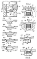
- Figure 1 illustrates one embodiment of a punch apparatus suitable for punching and forming a panel in accordance with the method of this invention.
- the punch apparatus includes a punch 20 having a body portion 22 and a punch portion 24.
- the punch portion 24 is cylindrical and has a diameter smaller than the diameter of the body portion 22 to receive a plastic spring member 26.
- the spring member 26 includes a cylindrical bore 28 which closely receives the cylindrical punch portion 24 of the punch.
- Plastic springs of the type shown in Figure 1 are commercially used for stripping the panel 30 from the punch and are sometimes referred to as a stripper. In the disclosed embodiment, however, the plastic spring functions not only as a stripper, but also deforms the metal panel in the die member 32, as described below. Such plastic springs are generally formed from a high density polyurethane.
- the die member 32 includes an annular die cavity 34 and a cylindrical bore 36 which receives the panel slug 38.
- the method steps performed by the apparatus shown in Figure 1 thus includes two steps.
- the cylindrical punch portion 24 punches a circular slug 38 from the panel 30, forming a circular opening or hole 42 in the panel.
- the panel is substantially simultaneously drawn and deformed into the annular die cavity 34 by the punch portion 24 and the plastic spring 26, forming a frusto-conical panel portion 40 adjacent the hole 42, as best shown in Figures 1A-1E discussed below.
- the panel may be drawn into the die cavity 34 and then punched or the steps may be separately performed.
- the panel slug 38 is removed through the cylindrical bore 36 of the die member.
- Figures 1A-1E illustrate cross-sections of panels of varying thickness punched and formed with the apparatus illustrated in Figure 1.
- the method of attaching a fastening element to a panel of this invention is suitable for attaching a fastening element to panels of different or varying thickness, such as utilized by the automotive industry.
- the panel shown in Figure 1A for example, has a thickness of 0.75-0.80 millimetres (mm).
- the panel illustrated in Figure 1E has a thickness of about 4 mm, which illustrates the range of panel thicknesses typically utilized by the automotive industry.
- Such panels are generally formed of steel, such as AISI 1008 or 1010 steel, which may be hot or cold rolled and are generally of commercial draw quality. Similar panels are used by many other industries.
- the appliance industry uses corrosion resistant and antimagnetic steels which are particularly suitable for the method of this invention because of their relatively poor weldability.
- Panels are used by the automotive industry for body panels, brackets and structural supports.
- the method of this invention may also be used to permanently install fastening elements in aluminium, copper and brass panels and other panels which require and installation of the type described herein. It is important to note, however, that the punch and forming apparatus shown in Figure 1 may be utilized to punch and form panels having a wide-range of panel thicknesses, such as illustrated in Figures 1A-1E.
- the thinner panels are punched and formed without extruding panel metal.
- a lip 44 is extruded axially by the punch portion 24, see 44C in Figure 1C, 44D in Figure 1D and 44E in Figure 1E. This extruded lip aids in the retention of the fastening element on the panel, as described below.
- the panel may also be punched and formed in separate operations on the frustoconical portion 40 may be formed in a configured die.
- the panel portion 40 may be characterized as frusto-conical shape or dome shape, wherein such terms are meant to include arcuate forms.
- FIGS 2-5 illustrate a female fastening element which may be installed in a panel 30 by the method of this invention.
- the term fastening element refers to a male or female fastening element preferably including a fastening portion, such as a threaded portion, which may be utilized to attach the panel to a second structural element, such as a panel, bracket or the like.
- Such fastening elements would therefore include a nut or bolt, as illustrated, and other fastening elements, including the male or female components of a ball joint and the like.
- the female fastening element or nut 50 illustrated in Figure 2 includes a body portion 52 and an annular or tubular barrel portion 54, preferably integral with the body portion and coaxially aligned with the threaded bore 56.
- the body portion 52 preferably includes an annular bearing face or surface 58, which preferably surrounds the tubular barrel portion 54, and a driven face 60.
- the free end 62 of the barrel portion 54 in the disclosed embodiment includes an annular internal chamber 64 and an arcuate outer surface 66.
- the internal surface 68 of the barrel portion is preferably smooth and the external surface 70 in the disclosed embodiment is cylindrical. As described below, however, the external surface 70 may be polygonal to provide improved torque resistance, including octagonal or hexagonal.
- the barrel portion 54 is preferably received through the panel hole 42 from adjacent the apex of the frusto-conical portion 40. That is, the fastening element is preferably received from the side of the panel opposite the side through which the punch 24 is received, as shown in Figure 1. Further, the diameter of the exterior surface 70 of the pilot portion is less than the internal diameter 42 of the domed panel. In the most preferred method, the barrel portion 54 is loosely received in the domed panel hole 42, reducing alignment problems.
- Figures 3-5 illustrate fastening element and panel assemblies which may be formed by the method of this invention.
- FIGS. 6 and 7 illustrate an embodiment of an installation apparatus suitable for installing fastening elements of the type described.
- the installation apparatus includes a plunger 80 having a configured cavity 82, which receives and supports the nut 150, and a die member 90 which supports the panel 30 during installation of the fastening element and which deforms the pilot portion 154 radially outwardly to form a mechanical interlock with the panel 30, as now described.
- a plunger 80 having a configured cavity 82, which receives and supports the nut 150
- a die member 90 which supports the panel 30 during installation of the fastening element and which deforms the pilot portion 154 radially outwardly to form a mechanical interlock with the panel 30, as now described.
- U.S. Patents 4,543,701, 4,555,838 and 4,610,072 which disclose self-piercing and riveting fastening elements having a tubular barrel portion.
- the fastening element 150 illustrated in Figures 6, 7 and 10 - 14 may be identical to the fastener 50 illustrated in Figures 2 - 5, except that the female fastening element 150 includes radially projecting anti-rotation ribs 84 as best illustrated in Figures 6, 10 and 11.
- the anti-rotation ribs 84 are generally triangular and integrally joined to the bearing surface 158 of the body portion 152 and the external surface 170 of the barrel portion 154.
- the numbering of the elements of the female fastening element 150 is therefore the same sequence as the fastening element 50.
- the die member 90 is generally referred to as a die button.
- the die button 90 includes axial bores 92 and 94 which relieve pressure during the installation of the fastening element 150.
- the die face includes a central projecting die post 96 having a frusto-conical side face 98, a first flat annular surface 100 and a second flat annular surface 102, joined to the first annular surface 100 by a second conical surface 104.
- the pilot portion 154 is loosely received in the hole 42 through the panel and the annular bearing face 158 is then driven against the panel adjacent the hole 42, deforming the frusto-conical panel portion 40 to a generally planar configuration as shown in Figure 7.
- the panel is deformed into a radially projecting portion 110 and a conical portion 112.
- the tubular barrel portion 154 is simultaneously deformed radially outwardly, as now described.
- the inside chamber 164 at the free end of the barrel portion is first received against the conical surface 98 of the die button post followed by the inside surface 168 of the barrel portion. These surfaces are then received against the annular flat surface 100, forming a radially outwardly projecting lip 116, as shown in Figure 7.
- the annular surface 100 simultaneously deforms the radially projecting barrel portion 116 toward the bearing surface 158 of the body portion, squeezing the assembly and forming an intimate laminate comprising the radially projecting barrel portion 116, the radially projecting panel portion 110 and the bearing surface 158.
- a secure mechanical interlock is thus formed between the fastening element 150 and the panel 30.
- the internal diameter of the hole 42 in the panel 30 in the flattened condition shown in Figure 7 is less than the external diameter of the barrel portion 154.
- the radially projecting panel portion 110 is thus driven radially inwardly against the external surface of the barrel portion into the radially projecting ribs 84, driving the ribs into the panel.
- the tubular barrel portion resiliently resists radial deformation, driving the ribs into the radially projecting panel portion 110.
- the stress thus created is commonly referred to as hoop stress after the stress created by a barrel hoop or stay. That is, strain energy is directed radially inwardly against the barrel, which is resisted by the resilient tubular barrel portion.
- the barrel portion 154 may be polygonal and inserted into a circular hole.
- a circular hole is, however, preferred to avoid stress risers.
- FIGs 8 and 9 illustrate a method of installing a male fastening element 250.
- the male fastening element is installed in a relatively thin panel of approximately the same thickness as the panel 30 shown in Figures 6 and 7.
- the male fastening element 250 includes a tubular or annular barrel portion 254 having a free end 262 configured as described above in regard to the fastening element 50 in Figure 2.
- the body portion 252 of the male fastening element has been modified somewhat to provide an enlarged bearing surface 258 which will provide direct clamp loading of the fastener assembly, as will be understood by those skilled in the art.
- the male fastening element also includes a threaded shank or bolt portion 320 which is formed integrally with the fastener and coaxially aligned with the barrel portion 254.
- the plunger cavity 282 has been modified to conform to and receive the body portion 252 of the male fastening element; however, the installation of the male fastener element is substantially identical to the method described above in regard to Figures 6 and 7 and the die button 90 may be identical to the die button shown in Figures 6 and 7.
- the barrel portion 254 is first received through the hole 42 in the panel 30 and the bearing surface 258 is driven against the panel, deforming the panel into the generally planar configuration shown in Figure 9, including a radially projecting portion 210 and a generally conical portion 212.
- the barrel portion 254 is deformed radially outwardly by the conical face 98 and the flat 100, forming a radially projecting portion 216, as shown in Figure 9.
- the radially projecting panel portion 210 is driven into the radially projecting ribs 284, forming secure anti-rotation means.
- the method of installing the male fastener 250 is substantially identical to the method of installing the female fastener 150 as described above in regard to Figures 6 and 7.
- Figures 6 - 9 illustrate a fastening element installed "downwardly", wherein the fastening element 150 or 250 is received and retained in a plunger 80 or 280 and the plunger is driven downwardly to engage the fastening element with a die button 90.
- the fastening element may be installed upwardly as would be illustrated by turning Figures 6 - 9 upside down.
- the panel can be turned over after the panel is punched and formed as shown in Figure 1.
- the panel should be softer than the nut. Most preferably, the hardness of the panel should be less than about 60 % of the hardness of the nut.
- the fastening element should have hardness and strength characteristics typical of those fasteners which meet the requirements of ISO Classes 8 through 12.
- the fastener may be formed from AISI 1035 steel and heat treated to the appropriate hardness.
- the method of this invention may be utilized to install fastening elements in most panels used in mass production applications. Further, it is important to note that the same fastener may be installed in panels having a wide range of thicknesses using the same or very similar installation tooling.
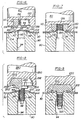
- FIGs 10 - 14 illustrate important details of the method of attaching fastening elements to a panel, particularly a thickener panel, as shown in Figure 1E, above.
- the fastening element 150 has been described above in regard to Figure 6.
- the fastening element includes a tubular barrel portion 154 and a plurality of radially projecting ribs 84.
- the fastening element 150 is installed in a relatively thick panel 30E using the same tooling as used in the thin panel shown in Figure 6. That is, the fastening element is received and supported within a cavity 82 in a plunger or punch 80 and driven through the panel opening 42E against the conical side surface 98 of the die post.
- the bearing surface 158 of the body portion 152 first engages the extruded portion 44E and the ribs 84 begin to bite into the panel as shown in Figure 12. Finally, the annular die surface 100 is driven into the now radially projecting panel portion 110 and the free end 116 of the barrel portion is deformed radially outwardly as shown in Figure 13, forming a secure installation.
- the extruded metal 44E helps to fill the C-shaped radially outwardly opening annular cavity formed by the barrel portion 154 and bearing surface 158 as shown in Figure 13.
- Figure 14 illustrates the deformation of the panel 30 during the installation of the fastener 150.
- the hole 42 through the frusto-conical portion 40 has an inside diameter greater than the external diameter of the barrel portion 154, such that the barrel portion 154 is loosely received in the panel hole 42 during the installation of the fastening element.
- the panel is then deformed to a generally planar configuration, as shown, wherein the hole 42 has a diameter which is slightly less than the external diameter of the barrel portion 154.
- the panel is thus driven radially inwardly against the barrel portion during the final installation of the fastening element, improving the resistance to rotation of the fastening element in the panel.
- the method of attaching a fastening element of this invention may be utilized to install fastening elements to panels having a wide range of panel thicknesses using the same fastening element and tooling.
- the fastening element 50 is installed in a panel having an intermediate thickness such as shown, for example, in Figure 1B.
- the radially deformed barrel portion 54 is flush with the panel 30.
- the panel does include a slight emboss 31, but the emboss is substantially less than the emboss formed in most applications.
- Figure 5 illustrates an installation of the female fastener 50 in a relatively thick panel, such as a panel having a thickness of 4 mm.
- the panel 30E has no emboss and the barrel portion 54 is flush with the panel.
- Figures 7 and 9 illustrate the installation of both male and female fastening elements in a relatively thin panel, such as the panel shown in Figure 1B.
- the panel 30 does include a more substantial emboss, but the emboss is less than that formed by other methods and the radially deformed barrel portion 216 is flush or actually recessed in the panel 30.
- the method of installing a fastening element of this invention may be utilized to install both male and female fastening elements in panels having a relatively wide range of panel thicknesses.
- the fastening elements are installed in panels ranging in thickness from 0,75 mm to 4 mm.
- the push out strength was found to be more consistent with a wider range of panel thicknesses than prior methods discussed above.
- the fastening element and panel assembly shows improved torque resistance with thinner panels. For example, a 25 % increase in torque resistance was found in a 0.8 mm panel compared to the fastener and panel assembly shown in U.S. Patent 4,831,698.
- the method of permanently attaching a fastening element to a plastically deformable panel of this invention achieves the goals of the invention discussed above.
- the fastening element may have a polygonal barrel portion to further improve the torque resistance of the fastening element in the panel.
- the frusto-conical or dome-shaped portion 40 may be modified by using a configured die.
- the panel hole is enlarged during the doming step, such that the barrel portion is loosely received in the panel hole during the final installation step.
- the method of this invention will be particularly useful for such applications as safety bolt anchors for automotive seat belt installations, particularly, in thinner panel metals.
- the fastening element may be installed in very thin panel metals now being used by both the automotive and appliance industries. Thus, it is anticipated that the method of this invention will find a broad range of applications.
Landscapes
- Engineering & Computer Science (AREA)
- Mechanical Engineering (AREA)
- General Engineering & Computer Science (AREA)
- Connection Of Plates (AREA)
- Insertion Pins And Rivets (AREA)
- Moulding By Coating Moulds (AREA)
- Lining Or Joining Of Plastics Or The Like (AREA)
Claims (21)
- Procédé de fixation d'un élément de liaison (50, 150, 250) à un panneau déformable plastiquement (30), ledit élément de liaison comprenant une partie creuse, ledit procédé comprenant :(a) la formation d'un trou (42) dans ledit panneau;(b) l'emboutissage et la déformation plastique dudit panneau (30) en une partie généralement bombée (40) entourant ledit trou (42) avec ledit trou d'un plus petit diamètre que ladite partie généralement bombée;(c) l'insertion de ladite partie creuse dudit élément de liaison (50, 150, 250) dans ledit trou (42) du panneau;(d) la déformation plastique de ladite partie généralement bombée du panneau de manière à diminuer le diamètre dudit trou (42) et du panneau autour du trou en engagement avec ladite partie creuse;caractérisé en ce que
le diamètre intérieur du trou (42) est inférieur au diamètre extérieur de la partie creuse lorsque le panneau est relativement plat, ladite partie creuse étant formée en une partie cylindre généralement tubulaire (54, 154, 254); en ce que ladite partie généralement bombée (40) du panneau est déformée en une forme généralement plane; et en ce qu'une extrémité de ladite partie cylindre généralement tubulaire (54, 154, 254) est simultanément déformée plastiquement radialement vers l'extérieur, formant un système de verrouillage mécanique réciproque entre ledit panneau (30) et ledit élément de liaison (50, 150, 250). - Procédé selon la revendication 1, dans lequel ledit trou (42) est formé par découpe dudit panneau (30) avec un poinçon généralement cylindrique (24), ledit panneau (30) étant supporté sur un élément de matrice (32), ledit panneau (30) étant ainsi simultanément embouti et déformé en ladite partie bombée (40) dans ledit élément de matrice (32) et découpé pour former ledit trou.
- Procédé selon la revendication 1 ou 2, dans lequel ledit élément de liaison comprend une partie corps (52, 152, 252) et ladite partie cylindre (54, 154, 254) s'étend depuis ladite partie corps, ladite partie corps comprenant une surface portante annulaire (58, 158, 258) entourant ladite partie cylindre (54, 154, 254) ayant un diamètre supérieur à celui dudit trou (42) du panneau, ledit procédé comprenant l'insertion de ladite partie cylindre (54, 154, 254) dans ledit trou (42) du panneau depuis ladite partie de plus petit diamètre de ladite partie bombée et l'entraînement de ladite surface portante annulaire (58, 158, 258) contre ledit panneau adjacent audit trou, de manière à déformer ladite partie bombée (40) en ladite forme généralement plane,
dans lequel ladite partie cylindre (54, 154, 254) est, de préférence, reçue dans ledit trou (40) du panneau dans un organe de matrice (90), ledit procédé comprenant, de préférence, l'entraînement de ladite surface portante de l'élément de liaison contre ledit panneau pour déformer ledit panneau (30) et à peu près simultanément déformer ladite partie cylindre (54, 154, 254) radialement vers l'extérieur dans ledit organe de matrice (90),
ledit organe de matrice (90) comprenant, de préférence, un pilier central (96) comportant une partie d'extrémité en projection et une surface latérale généralement conique (98) recevant une surface interne de ladite partie cylindre tubulaire, ladite surface conique, déformant ladite extrémité libre de ladite partie cylindre radialement vers l'extérieur (116, 216) et emprisonnant une partie se projetant radialement (110, 210) dudit panneau (30) adjacente audit trou entre ladite extrémité libre déformée radialement (116, 216) de ladite partie cylindre et ladite surface portante de ladite partie corps; et
dans lequel ledit procédé comprend en outre, de manière facultative, la pression de ladite extrémité libre (116, 216) de la partie cylindre vers ladite surface portante (58, 158, 258) de manière à comprimer ladite partie du panneau se projetant radialement (110, 210), ce qui aboutit à un laminé intime et un positionnement sensiblement de niveau dudit élément de liaison (50, 150, 250) dans ledit panneau (30). - Procédé selon la revendication 1, ledit panneau étant un panneau de métal déformable plastiquement, ledit élément de liaison comprenant une partie corps (52, 152, 252) comportant une surface portante annulaire (58, 158, 258) entourant ladite partie cylindre tubulaire (54, 154, 254), ledit procédé comprenant, en outre, les phases de :insertion de ladite partie cylindre tubulaire (54, 154, 254) dans ledit trou depuis un emplacement adjacent au sommet de ladite partie généralement tronconique (40) et ladite surface portante (58, 158, 258) de ladite partie cylindre tubulaire (54, 154, 254) engageant une partie du panneau entourant ledit trou du panneau; etentraînement de ladite surface portante annulaire (58, 158, 258) de la partie corps dudit élément de liaison contre ladite partie du panneau entourant ledit trou de manière à déformer plastiquement ladite partie tronconique (40) du panneau en ladite forme généralement plane et réaliser à peu près simultanément ladite déformation plastique d'une extrémité libre en projection (116, 216) de ladite partie cylindre tubulaire (54, 154, 254) radialement vers l'extérieur, ce qui emprisonne ladite partie (40) du panneau entre ladite surface portante annulaire (58, 158, 258) et ladite extrémité libre déformée radialement (116, 216) de la partie cylindre.
- Procédé selon la revendication 4, dans lequel ledit panneau est supporté sur un élément de matrice (32) comportant une cavité de matrice annulaire (34), ledit procédé comprenant l'entraînement d'un poinçon (20) contre ledit panneau (30), la déformation et l'emboutissage dudit panneau (30) dans ladite cavité de matrice annulaire (34) en ladite partie de panneau tronconique et la découpe d'un trou (42) dans ledit panneau (30).
- Procédé selon la revendication 5, dans lequel ledit poinçon (20) forme un bec se projetant axialement (446, 44D, 44E) entourant ledit trou (42), ledit procédé comprenant l'entraînement de ladite surface portante (58, 158, 258) contre ledit bec et la déformation dudit bec (44C, 44D, 44E) entre ladite surface portante (58, 158, 258) et ladite partie cylindre déformée radialement (54, 154, 254).
- Procédé selon l'une quelconque des revendications 1 à 6, dans lequel ladite phase d'emboutissage et de déformation plastique dudit panneau (30) en une partie généralement bombée (40) comprend l'opération consistant à amener de force un organe élastique en plastique (26) contre ledit panneau (30) adjacent audit trou (42).
- Procédé selon l'une quelconque des revendications 4 à 6, dans lequel ladite partie de panneau tronconique (40) est reçue et supportée sur un organe de matrice (90), ledit organe de matrice (90) comprenant un pilier de matrice central (96) comportant une partie d'extrémité en projection alignée co-axialement avec ladite partie cylindre tubulaire de l'élément de liaison et une surface latérale conique (98) recevant une surface interne (68, 168) de ladite partie cylindre tubulaire (54, 154, 254), ladite surface de matrice conique déformant une extrémité libre (116, 216) de ladite partie cylindre radialement vers l'extérieur, emprisonnant une partie se projetant radialement (110, 210) dudit panneau adjacente audit trou du panneau entre ladite extrémité libre déformée radialement (116, 216) de ladite partie cylindre et ladite surface portante annulaire (58, 158, 258) de ladite partie corps, ledit procédé comprenant, de préférence, la phase supplémentaire de pression de ladite extrémité libre (116, 216) de la partie cylindre vers ladite surface portante (58, 158, 258) de manière à comprimer ledit panneau (30) et former un laminé intime comprenant ladite extrémité libre (116, 216) de la partie cylindre, ledit panneau (30) et ladite surface portante (58, 158, 258).
- Procédé selon la revendication 1, ledit panneau se présentant sous la forme d'un panneau de métal ayant une épaisseur dans les limites d'une plage d'épaisseurs de panneau, ledit élément de liaison (50, 150, 250) comprenant une partie corps (52, 152, 252) comportant une surface portante (58, 158, 258) sur au moins les faces opposées de ladite partie cylindre, ledit procédé comprenant les phases supplémentaires de :réception à frottement doux de ladite partie cylindre dans ledit trou du panneau par insertion d'une extrémité libre (116, 216) de ladite partie cylindre dans ledit trou du panneau et entraînement de ladite surface portante (58, 158, 258) de la partie corps de l'élément de liaison contre une partie du panneau (40) adjacente audit trou, de manière à déformer ladite partie conique (40) du panneau en ladite forme généralement plane,dans lequel ladite partie corps de l'élément de liaison comprend une pluralité de nervures en projection radialement espacées (84, 284) adjacentes à ladite surface portante, et ledit procédé comprend l'entraînement de ladite partie du panneau (40) radialement dans lesdites nervures tandis que ladite partie conique (40) du panneau est déformée en ladite forme généralement plane et ladite partie cylindre tubulaire (54, 154, 254) entraînant élastiquement lesdites nervures dans ladite partie du panneau, afin de constituer des moyens d'anti-rotation sûrs entre ledit élément de liaison et ledit panneau; et dans lequel ledit procédé comprend en outre la pression de ladite extrémité libre (116, 216) de la partie cylindre vers ladite surface portante (58, 158, 258) de ladite partie corps, de manière à comprimer ladite partie du panneau (40) et former un laminé intime de ladite extrémité libre déformée radialement (116, 216) de la partie cylindre, d'une partie du panneau se projetant radialement (110, 210) et de ladite surface portante (58, 158, 258) de ladite partie corps.
- Procédé selon la revendication 9, dans lequel ledit trou (42) est formé par un poinçon (20) tandis que ledit panneau est supporté sur un élément de matrice (32) comportant une cavité de matrice annulaire (34), ledit poinçon découpant un trou (42) dans ledit panneau et emboutissant et déformant plastiquement simultanément ledit panneau (30) entourant ledit trou dans ladite cavité de matrice de l'élément de matrice en ladite partie généralement conique (40).
- Procédé selon la revendication 9 ou 10, dans lequel ledit procédé comprend l'entraînement de ladite surface portante (58, 158, 258) de la partie corps de l'élément de liaison contre ladite partie du panneau adjacente audit trou, ce qui déforme ladite partie conique (40) du panneau en une forme généralement plane et déforme à peu près simultanément ladite extrémité libre (116, 216) de ladite partie cylindre tubulaire (54, 154, 254) radialement vers l'extérieur de manière à former ledit système de verrouillage mécanique réciproque.
- Ensemble de panneau déformable plastiquement (30) et d'au moins un élément de liaison (50, 150, 250) comportant une partie corps (52) sur une face dudit panneau (30), une partie creuse passant dans un trou (42) dans ledit panneau (30) et une partie s'étendant radialement (116, 216) sur la face opposée dudit panneau depuis ladite partie corps, ce qui forme un système de verrouillage mécanique réciproque entre ledit panneau (30) et ledit élément de liaison (50, 150, 250), avec ladite partie corps (52, 152, 252) comportant une paroi latérale et une surface portante (58, 158, 258) s'étendant entre ladite paroi latérale et ladite partie corps, dans lequel ledit élément de liaison comprend un élément de rivetage comprenant ladite partie corps (52, 152, 252) et une partie cylindre de rivetage tubulaire (54, 154, 254) comportant une extrémité libre (62) et définissant ladite partie creuse et ladite partie s'étendant radialement (116, 216), avec ladite partie cylindre tubulaire étant reçue dans ledit trou (42) du panneau et ladite extrémité libre (62) de la partie cylindre étant déformée radialement pour engager ledit panneau et comprimer ledit panneau (30) entre ladite partie cylindre déformée radialement (54, 154, 254) et ladite surface portante (58, 158, 258), caractérisé en ce que ladite partie dudit panneau comprimée entre ladite partie cylindre déformée et ladite surface portante est une partie de panneau déformée plastiquement et s'étend généralement parallèlement à ladite surface portante (58, 158, 258) qui est une surface radiale, et en ce que le matériau dudit panneau (30) adjacent audit trou présente une contrainte périphérique en compression permanente étant, de préférence, juste inférieure à la résistance élastique dudit matériau déformable plastiquement.
- Ensemble selon la revendication 12, caractérisé en ce que ledit panneau (30) exerce une force de compression permanente sur au moins une majeure partie de la surface (70 et/ou 116, 216; 58, 158, 258) dudit élément de liaison en engagement de verrouillage mécanique réciproque avec ledit panneau.
- Ensemble selon la revendication 12 ou 13, caractérisé en ce que ladite une face dudit panneau (30) est coplanaire à une surface externe de ladite partie déformée radialement (116, 216) de manière que ladite partie déformée radialement ne se projette pas au-delà de ladite une face dans une direction s'éloignant de ladite face opposée.
- Ensemble selon la revendication 14, lorsqu'utilisé en combinaison avec ladite une face dudit panneau (30) adjacente à une face d'un autre panneau parallèle et fixée à celui-ci, au moins en partie, par un élément de liaison coopérant avec ledit au moins un élément de liaison (50, 150, 250).
- Ensemble selon l'une quelconque des revendications 12 à 15, caractérisé en ce que ledit trou (42) dans ledit panneau (30) est formé dans une partie dudit panneau qui se fond via une partie sensiblement tronconique (31, 112, 212) dudit panneau dans le restant dudit panneau (30), avec ladite partie déformée radialement (116, 216) dudit élément de liaison se situant généralement au sein de ladite partie tronconique.
- Ensemble selon l'une quelconque des revendications 12 à 16, caractérisé en ce que ledit élément de liaison comporte une partie cylindre (54, 154, 254) reçue dans ledit trou et est doté de formations telles que des nervures arrondies se projetant radialement (84, 284) ou des angles, par exemple les angles d'une partie cylindre généralement polygonale.
- Ensemble selon l'une quelconque des revendications 12 à 17, caractérisé en ce que la dureté dudit panneau (30) est de moins de 60 % de la dureté de l'élément de liaison (50, 150, 250).
- Ensemble selon l'une quelconque des revendications 12 à 18, dans lequel ledit élément de rivetage comprend une partie goujon (320) outre ladite partie cylindre de rivetage tubulaire (254) et ladite partie corps (252), ladite partie cylindre tubulaire (254) s'étendant depuis ladite partie corps (252) et entourant ladite partie goujon (320).
- Utilisation d'un élément de rivetage à goujon dans le procédé de la revendication 1, ledit élément de rivetage comprenant un corps allongé (320) et une partie tête (252), ledit corps allongé en extension de ladite partie tête (252) et d'une seule pièce avec elle, ladite partie tête comprenant une partie cylindre tubulaire (254) entourant ledit corps allongé (320),
ladite partie tête (252) comprenant en outre une cuvette annulaire entourant ladite partie cylindre tubulaire (254), dans laquelle une partie de ladite surface de la cuvette définit une surface portante radiale (258), et dans laquelle ladite partie tête comprend des projections (284) s'étendant depuis ladite surface portante radiale. - Utilisation d'un élément de liaison sous la forme d'un écrou creux dans le procédé de la revendication 1, ledit élément de liaison comprenant une partie corps (52, 152), une partie cylindre tubulaire (54, 154) s'étendant depuis ladite partie corps, ladite partie corps (52, 152) comportant une surface portante annulaire dirigée radialement (58, 158) entourant ladite partie cylindre tubulaire, et une pluralité de nervures d'anti-rotation dirigées radialement (84) à la transition entre ladite surface portante annulaire (58, 158) et ladite partie cylindre (54, 154), caractérisée en ce que l'élément de liaison sous forme d'écrou comporte une partie cylindre tubulaire d'une longueur adaptée à une utilisation avec un panneau d'une épaisseur dans la plage de 0,75 mm à 4 mm, de sorte que, avec des panneaux minces d'une épaisseur supérieure ou égale à 0,75 mm, mais inférieure à 4 mm, la partie cylindre soit déformée plastiquement radialement vers l'extérieur pour former un rebord dirigé radialement (54, figures 3 et 4) espacé de ladite surface portante annulaire dirigée radialement (58, 158) d'une distance égale à l'épaisseur dudit panneau et se termine en ledit rebord dirigé radialement, tandis qu'avec des panneaux plus épais de 4 mm la partie cylindre soit déformée plastiquement en un rebord conique divergent (54, figure 5) espacé de ladite surface portante annulaire dirigée radialement d'une distance maximale inférieure à l'épaisseur du panneau, et se termine en ledit rebord.
Applications Claiming Priority (2)
| Application Number | Priority Date | Filing Date | Title |
|---|---|---|---|
| US786204 | 1991-10-31 | ||
| US07/786,204 US5251370A (en) | 1991-10-31 | 1991-10-31 | Method of attaching a fastening element to a panel |
Publications (2)
| Publication Number | Publication Date |
|---|---|
| EP0539793A1 EP0539793A1 (fr) | 1993-05-05 |
| EP0539793B1 true EP0539793B1 (fr) | 1996-12-27 |
Family
ID=25137890
Family Applications (1)
| Application Number | Title | Priority Date | Filing Date |
|---|---|---|---|
| EP92117466A Expired - Lifetime EP0539793B1 (fr) | 1991-10-31 | 1992-10-13 | Procédé pour la fixation d'un élément de liaison à un panneau et combinaison d'un panneau et au moins d'un élément de liaison |
Country Status (7)
| Country | Link |
|---|---|
| US (2) | US5251370A (fr) |
| EP (1) | EP0539793B1 (fr) |
| JP (1) | JP3452203B2 (fr) |
| KR (1) | KR100249118B1 (fr) |
| CA (1) | CA2081688C (fr) |
| DE (1) | DE69216206T2 (fr) |
| ES (1) | ES2096002T3 (fr) |
Cited By (8)
| Publication number | Priority date | Publication date | Assignee | Title |
|---|---|---|---|---|
| DE102004043688A1 (de) * | 2004-06-23 | 2006-04-06 | Profil-Verbindungstechnik Gmbh & Co. Kg | Verfahren zur Herstellung eines Zusammenbauteils bestehend aus einem Blechteil und einem an diesem angebrachten Funktionselement, Blechteil sowie Funktionselement |
| US7155798B2 (en) | 2003-07-25 | 2007-01-02 | Profil Verbindungstechnik Gmbh & Co. Kg | Method for the attachment of a functional element to a sheet metal part and also a component assembly |
| WO2007065398A1 (fr) | 2005-12-09 | 2007-06-14 | Heiko Schmidt | Procédé pour appliquer un élément fonctionnel sur un matériau plat et liaison entre un élément fonctionnel et un matériau plat |
| WO2008138315A2 (fr) | 2007-05-14 | 2008-11-20 | Heiko Schmidt | Procédé pour fixer un élément d'assemblage ou fonctionnel sur un matériau plat, assemblage riveté et élément d'assemblage ou fonctionnel |
| US7815406B2 (en) | 2004-12-23 | 2010-10-19 | Profil Verbindungstechnik Gmbh & Co., Kg | Element attachable by riveting to a sheet metal part and also a component assembly and a method for the production of the component assembly |
| US8210315B2 (en) | 2008-02-29 | 2012-07-03 | Profil Verbindungstechnik Gmbh & Co., Kg | Component assembly comprising a sheet metal part and a nut element attached thereto and also a method for the manufacture of such a component assembly |
| DE102011104971A1 (de) | 2011-06-20 | 2012-12-20 | Profil Verbindungstechnik Gmbh & Co. Kg | Einteiliges Funktionselement in der Form eines hohlen Nietelements |
| DE102011108987A1 (de) | 2011-08-01 | 2013-02-07 | Thyssenkrupp System Engineering Gmbh | Verfahren zum Kelchen eines Werkstücks, Verfahren zum Einpressen eines Nietelements in ein Werkstück und Werkzeug |
Families Citing this family (94)
| Publication number | Priority date | Publication date | Assignee | Title |
|---|---|---|---|---|
| US5564873A (en) * | 1980-02-02 | 1996-10-15 | Multifastener Corporation | Self-attaching fastening element and method of attachment |
| US5722139A (en) * | 1981-01-28 | 1998-03-03 | Multifastener Corporation | Installation apparatus for attaching a fastener to a panel |
| DE4410475A1 (de) * | 1994-03-25 | 1995-09-28 | Profil Verbindungstechnik Gmbh | Vernietbares Element, Zusammenbauteil mit einem vernietbaren Element sowie Nietmatrize und Verfahren zur Herstellung des Zusammenbauteils |
| US5528812A (en) * | 1991-10-31 | 1996-06-25 | Profil-Verbindungstechnik Gmbh & Co. Kg | Method of attaching a fastener to a plurality of panels |
| CZ285213B6 (cs) * | 1992-07-07 | 1999-06-16 | Richard Bergner Gmbh And Co. | Vložkový díl pro vtlačování, ve formě spojovacího prvku a způsob jeho výroby |
| US6125524A (en) * | 1994-03-25 | 2000-10-03 | Multifastener Corporation | Rivetable element, assembly, method of assembly and riveting die |
| JP3670714B2 (ja) * | 1994-05-31 | 2005-07-13 | Ntn株式会社 | 等速ジョイントの外輪と軸の接合構造 |
| DE4444908A1 (de) * | 1994-12-16 | 1996-06-27 | Hilti Ag | Befestigungselement |
| JP3090588B2 (ja) * | 1995-05-12 | 2000-09-25 | 株式会社ソミック石川 | ボールジョイント |
| US5711549A (en) * | 1995-06-07 | 1998-01-27 | Itt Automotive, Inc. | High pressure quick connect for use in automotive brake system application |
| US5713116A (en) * | 1995-07-13 | 1998-02-03 | Penn Engineering & Manufacturing Corp. | Clinch-type lock nut installation and formation process |
| US5882159A (en) * | 1996-08-16 | 1999-03-16 | Profil Verbindungstechnik, Gmbh & Co. | Element, method of attaching the element to a plate-like component, component assembly and die button |
| DE19612619C2 (de) * | 1996-03-29 | 2001-07-26 | Hecralmat Schaan Fa | Verfahren zur Herstellung einer Lochverstärkung in einem Blech mittels einer Scheibe, sowie Lochverstärkung |
| IT1285832B1 (it) * | 1996-03-29 | 1998-06-24 | Roltra Morse Spa | Punto di fissaggio rinfozato |
| US5882049A (en) * | 1996-12-18 | 1999-03-16 | Itt Automotive, Inc. | High pressure quick connect with reduced volumetric displacement and piloted snap ring |
| US5839848A (en) * | 1996-12-30 | 1998-11-24 | Sahramaa; Kimmo J | Joining metal members |
| US6113151A (en) * | 1998-01-27 | 2000-09-05 | Itt Manufacturing Enterprises, Inc. | High pressure quick connect and production process therefor |
| AU2505299A (en) | 1998-02-17 | 1999-09-06 | Cosma International Inc. | Self-extruded bushing assembly and method of making the same |
| SE523534C2 (sv) * | 1998-03-10 | 2004-04-27 | Oehlins Racing Ab | Ventil- eller tryckregulatoranordning för att effektuera öppnings och/eller stängningsfunktioner eller rörelser för två från och mot varandra arbetande delar, t ex kägla/slid respektive säte/hus. |
| DE19832150A1 (de) * | 1998-07-17 | 2000-01-20 | Bosch Gmbh Robert | Scheibe, insbesondere Dichtungsscheibe |
| US6412826B1 (en) | 1999-04-16 | 2002-07-02 | Itt Manufacturing Enterprises, Inc. | High pressure quick connector |
| US7731467B2 (en) * | 1999-07-09 | 2010-06-08 | Profil Verbindungstechnik Gmbh & Co., Kg | Bolt element having a shaft part and a spherical head, component assembly and method for the manufacture of a bolt element |
| WO2001027493A1 (fr) * | 1999-10-14 | 2001-04-19 | Johann Gersbach | Elements de fixation de courroie |
| DE60025300T2 (de) * | 1999-10-18 | 2006-09-21 | Kabushiki Kaisha Yutaka Giken, Hamamatsu | Nietverbindung und Verfahren um zwei Teile mittels Nieten zu verbinden |
| ES2242709T3 (es) * | 2000-03-10 | 2005-11-16 | Arvinmeritor Light Vehicle Systems-France | Metodo y aparato para montar un mecanismo de accionamiento en el interior de un modulo de una puerta. |
| US6517344B2 (en) * | 2000-05-26 | 2003-02-11 | Brass-Craft Manufacturing Company | Gas supply coupling for water heater |
| US6474918B1 (en) | 2000-06-30 | 2002-11-05 | Ashton Plastic Products, Inc. | Anti-cross threading device |
| GB0030097D0 (en) * | 2000-12-09 | 2001-01-24 | Meritor Light Vehicle Sys Ltd | Assembly |
| CA2671515C (fr) | 2000-12-29 | 2012-12-18 | Profil Verbindungstechnik Gmbh & Co. Kg | Element tourillon presentant une partie tige et une tete spherique, composant d'assemblage et procede de fabrication d'un element tourillon |
| DE10104549A1 (de) * | 2001-02-01 | 2002-08-08 | Profil Verbindungstechnik Gmbh | Verfahren zum Anbringen eines Funktionselementes an ein verformbares Metallteil unter Anwendung eines Hochdruckumformverfahrens, Zusammenbauteil und Matrize |
| DE10243759B4 (de) * | 2002-09-20 | 2011-08-11 | PROFIL Verbindungstechnik GmbH & Co. KG, 61381 | Verfahren zur Erzeugung einer elektrisch leitenden Verbindung zwischen einer elektrischen Anschlusseinrichtung wie ein Kabelschuh und einem Blechteil, Befestigungselement und Zusammenbauteil |
| DE10114200A1 (de) | 2001-03-23 | 2002-09-26 | Profil Verbindungstechnik Gmbh | Funktionselement, Zusammenbauteil bestehend aus einem Blechteil und einem Funktionselement sowie Verfahren zur Anbringung eines Funktionselementes an ein Blechteil |
| DE10117060A1 (de) | 2001-04-05 | 2002-10-10 | Profil Verbindungstechnik Gmbh | Verfahren zum Anbringen eines Funktionselements an ein Bauteil sowie dazugehöriges Werkzeug |
| US6453558B1 (en) * | 2001-04-06 | 2002-09-24 | Arvinmeritor, Inc. | Method of locking together exhaust components |
| DE10118149A1 (de) * | 2001-04-11 | 2002-10-17 | Profil Verbindungstechnik Gmbh | Verfahren zum Anbringen eines Funktionselements an ein Bauteil sowie dazugehöriges Werkzeug |
| DE10119505A1 (de) | 2001-04-20 | 2002-10-24 | Profil Verbindungstechnik Gmbh | Funktionselement zur Anbringung an ein Blechteil, aus diesen hergestelltes Zusammenbauteil sowie Verfahren zur Anbringung des Funktionselements an ein Bauteil |
| US7124492B2 (en) * | 2001-07-19 | 2006-10-24 | Whitesell International Corporation | Fastener, method of attaching a fastener to a panel and fastener and panel assembly |
| US6592311B2 (en) | 2001-07-19 | 2003-07-15 | Fabristeel Products, Inc. | Double-ended self-attaching stud |
| US8092131B2 (en) * | 2001-07-19 | 2012-01-10 | Whitesell International Corporation | Clinch spacer and method of attaching the same to a panel |
| US6491487B1 (en) * | 2001-07-19 | 2002-12-10 | Fabristeel Products, Inc. | Double-ended self-attaching stud |
| US7698799B2 (en) * | 2001-07-19 | 2010-04-20 | Whitesell International Corporation | Method of attaching a clinch spacer to a panel |
| ATE338215T1 (de) * | 2001-08-15 | 2006-09-15 | Whitesell Int Corp | Selbstsicherndes befestigungselement |
| US7516534B2 (en) * | 2001-11-25 | 2009-04-14 | Stresswave, Inc. | Method for attaching a nut element to a metal structure |
| ES2254791T3 (es) * | 2002-01-22 | 2006-06-16 | Whitesell International Corporation | Procedimiento de conformacion en frio de un elemento de fijacion hembra autofijable. |
| DE60214434T2 (de) | 2002-01-22 | 2007-08-30 | Whitesell International Corp., Taylor | Selbst-durchdringende befestigungsmutter und verfahren zur herstellung eines abgedichteten paneelzusammenbau mit solchen befestigungsmuttern |
| BR0202511A (pt) * | 2002-07-03 | 2004-05-11 | Manegro Administracao E Partic | Junta de vedação de flanges de tubulações e equipamentos, processo de fabricação da junta de vedação, e anel de vedação para junta de vedação |
| US6851904B2 (en) * | 2002-08-30 | 2005-02-08 | Fabristeel Products, Inc. | Self-attaching female fastener and method of installation |
| US7591623B2 (en) * | 2002-08-30 | 2009-09-22 | Whitesell International Corporation | Heavy metal pierce nut |
| US7112024B2 (en) * | 2002-08-30 | 2006-09-26 | Whitesell International Corporation | Self-attaching nut |
| US20040146375A1 (en) * | 2002-08-30 | 2004-07-29 | Ward Richard P. | Self-attaching nut |
| US20040042871A1 (en) | 2002-09-04 | 2004-03-04 | Wojciechowski Stanley E. | Self-attaching female fastener element, sealed fastener and panel assembly and method of forming same |
| US20050111934A1 (en) * | 2003-11-14 | 2005-05-26 | Ladouceur Harold A. | Self-riveting male fastener and panel assembly |
| MXPA05004241A (es) * | 2002-10-23 | 2005-07-05 | Fabristeel Prod Inc | Sujetadores hembra de autounion y metodo de formar elementos sujetadores hembra. |
| AU2003286627A1 (en) * | 2002-10-23 | 2004-05-13 | Fabristeel Products, Inc. | Self-attaching female fastener element and method of installation |
| DE102004004384B4 (de) * | 2004-01-29 | 2006-05-18 | Daimlerchrysler Ag | Verfahren und Vorrichtung zur Befestigung einer Nietmutter an einem Werkstück |
| GB0406390D0 (en) * | 2004-03-22 | 2004-04-21 | Bas Components Ltd | Vehicle roofrack mounting |
| RU2355550C2 (ru) * | 2004-03-24 | 2009-05-20 | Фриатек Акциенгезельшафт | Установочный элемент |
| DE102004017866A1 (de) * | 2004-04-13 | 2005-11-03 | Profil-Verbindungstechnik Gmbh & Co. Kg | Verfahren zur Herstellung von Hohlkörperelementen, Hohlkörperelement, Zusammenbauteil sowie Folgeverbundwerkzeug zur Durchführung des Verfahrens |
| DE102004020675A1 (de) * | 2004-04-28 | 2005-11-24 | Profil Verbindungstechnik Gmbh & Co. Kg | Verfahren und Vorrichtung zur Anbringung eines Befestigungselements an ein Bauteil, insbesondere an ein Blechteil |
| DE102004030223A1 (de) * | 2004-06-23 | 2006-01-12 | Profil Verbindungstechnik Gmbh & Co. Kg | Verfahren zur Herstellung eines Zusammenbauteils bestehend aus einem Blechteil und einem an diesem angebrachten Funktionselement, Blechteil sowie Funktionselement |
| US7480971B2 (en) | 2005-04-28 | 2009-01-27 | Profile Verbindungstechnik Gmbh & Co., Kg | Method and device for mounting a fastener element on a part, particularly a sheet metal part |
| DE102005024220A1 (de) * | 2005-05-25 | 2006-11-30 | Profil Verbindungstechnik Gmbh & Co. Kg | Verfahren zum Herstellen von Hohlkörperelementen, Hohlkörperelement, Zusammenbauteil, Folgeverbundwerkzeug zum Herstellen von Hohlkörperelementen sowie Walzwerk |
| RU2418206C2 (ru) * | 2006-01-05 | 2011-05-10 | Профиль-Фербиндунгстехник Гмбх Унд Ко. Кг | Крепежный элемент, узловая сборка, состоящая из крепежного элемента и детали из листового металла, а также способ закрепления крепежного элемента на детали из листового металла |
| JP5148074B2 (ja) * | 2006-05-24 | 2013-02-20 | プロフィル・フェルビンドゥングステヒニック・ゲーエムベーハー・ウント・コンパニー・カーゲー | リベット締めによってシートメタル部に取り付け可能な部材と部品アッセンブリ並びにその部品アッセンブリの製造方法 |
| DE202006008721U1 (de) | 2006-06-01 | 2007-10-11 | Profil Verbindungstechnik Gmbh & Co. Kg | Nietmutter und Kombination einer Nietmutter mit einem Blechteil |
| DE102006050640A1 (de) * | 2006-10-26 | 2008-04-30 | Profil-Verbindungstechnik Gmbh & Co. Kg | Befestigungselement sowie Zusammenbauteil bestehend aus dem Befestigungselement und einem Blechteil |
| CN101210582A (zh) * | 2006-12-28 | 2008-07-02 | 鸿富锦精密工业(深圳)有限公司 | 螺柱 |
| WO2008138286A2 (fr) * | 2007-05-14 | 2008-11-20 | Heiko Schmidt | Procédé pour installer un élément d'assemblage ou fonctionnel sur un matériau plat et élément d'assemblage ou fonctionnel utilise a cet effet |
| US8608420B2 (en) * | 2007-08-24 | 2013-12-17 | Whitesell International Corporation | Self-attaching nut |
| US8142125B2 (en) * | 2007-08-24 | 2012-03-27 | Whitesell International Corporation | Self-attaching female fastener |
| DE102008016273B4 (de) | 2007-12-21 | 2019-05-23 | Heiko Schmidt | Verfahren zum Verbinden eines Funktionselementes mit einem Metallblech sowie Verbindung zwischen einem Metallblech und einem Funktionselement |
| US8092115B1 (en) * | 2008-07-14 | 2012-01-10 | Cisco Technology, Inc. | Entrapped nut |
| DE102008052383A1 (de) * | 2008-10-20 | 2010-04-22 | Profil Verbindungstechnik Gmbh & Co. Kg | Zusammenbauteil bestehend aus einem Befestigungselement und einem Blechteil sowie ein Verfahren zur Herstellung eines solchen Zusammenbauteils |
| US20120056421A1 (en) * | 2009-05-12 | 2012-03-08 | Illinois Tool Works Inc. | System and method for securing a nut to an oil pan |
| DE102009039817A1 (de) * | 2009-09-02 | 2011-03-03 | Profil Verbindungstechnik Gmbh & Co. Kg | Selbststanzendes Mutterelement und Zusammenbauteil bestehend aus dem Mutterelement und einem Blechteil |
| DE102009042336A1 (de) * | 2009-09-21 | 2011-03-24 | Profil Verbindungstechnik Gmbh & Co. Kg | Selbststanzendes hohles Einpresselement, Zusammenbauteil bestehend aus einem Einpresselement und einem Blechteil sowie ein Verfahren zur Herstellung einer selbststanzenden Einpressmutter sowie zur Anbringung einer selbststanzenden Einpressmutter |
| US9205520B2 (en) * | 2011-01-18 | 2015-12-08 | Pem Management, Inc. | One-hit tooling for flush mounted rotatable captive nut |
| DE102011108224A1 (de) | 2011-07-21 | 2013-01-24 | Profil Verbindungstechnik Gmbh & Co. Kg | Funktionselement mit Verdrehsicherungsmerkmalen sowie Zusammenbauteil bestehend aus dem Funktionselement und einem Blechteil |
| US20140068921A1 (en) * | 2012-09-09 | 2014-03-13 | Hanwit Precision Industries Ltd. | Floating fastener mounting structure and method |
| US9695852B2 (en) | 2012-09-09 | 2017-07-04 | Hanwit Precision Industries Ltd. | Floating fastener mounting structure |
| US9746015B2 (en) | 2012-09-09 | 2017-08-29 | Hanwit Precision Industries Ltd. | Floating fastener mounting structure |
| US9352639B2 (en) | 2013-10-22 | 2016-05-31 | Halcore Group, Inc. | Service vehicle door system |
| US9435362B2 (en) | 2014-03-05 | 2016-09-06 | Morgan Truck Body, Llc | Bolt and nut assembly with plastic cover for controlled sealing compression |
| US9688185B2 (en) | 2014-03-05 | 2017-06-27 | Halcore Group, Inc. | Corner light assembly for emergency vehicle |
| US9296432B2 (en) * | 2014-06-06 | 2016-03-29 | Ford Global Technologies, Llc | Aluminum alloy vehicle structural component defining an out-of-plane aperture |
| US10161435B2 (en) | 2016-02-15 | 2018-12-25 | Whitesell Formed Components, Inc. | Self-attaching fastener and panel assembly, and method of attaching |
| KR20170105240A (ko) * | 2016-03-09 | 2017-09-19 | (주)명하테크 | 부시 압착용 금형구조 |
| DE102016204619B4 (de) | 2016-03-21 | 2019-10-17 | Richard Bergner Verbindungstechnik Gmbh & Co. Kg | Einpressverbindung zwischen einem hochfesten Bauteil und einem Einpresselement, Verfahren zur Ausbildung einer solchen Einpressverbindung sowie Einpresselement für eine solche Einpressverbindung |
| FR3068541B1 (fr) * | 2017-06-28 | 2019-07-19 | Valeo Equipements Electriques Moteur | Assemblage de pieces et procede de fabrication d’un tel assemblage |
| CN109236404B (zh) * | 2017-07-11 | 2021-08-31 | 美国材料科学公司 | 包括层压体和铆螺母的油底壳组件 |
| JP7156124B2 (ja) * | 2019-03-25 | 2022-10-19 | 株式会社Jvcケンウッド | スタッドピンおよびスタッドピンのかしめ方法 |
| DE202019104970U1 (de) * | 2019-09-09 | 2020-12-10 | Böllhoff Verbindungstechnik GmbH | Kugelbolzen |
| TWI742788B (zh) * | 2020-08-03 | 2021-10-11 | 伍鐌科技股份有限公司 | 浮動元件 |
| CN117817293A (zh) * | 2023-08-16 | 2024-04-05 | 上海轩田工业设备有限公司 | 一种带强磁永磁动子的磁钢装配机构 |
Family Cites Families (28)
| Publication number | Priority date | Publication date | Assignee | Title |
|---|---|---|---|---|
| US1502399A (en) * | 1923-05-14 | 1924-07-22 | Harold G Renner | Rivetable nut |
| US1579875A (en) * | 1924-03-24 | 1926-04-06 | Briggs Mfg Co | Snap-on nut |
| GB318182A (en) * | 1928-04-10 | 1929-08-12 | Daniel Hall | Improvements in or relating to securing parts or articles to metal and other plates, sheets and the like by riveting |
| US1976019A (en) * | 1928-12-28 | 1934-10-09 | Lewis R Heim | Art of making roller bearings |
| US1872385A (en) * | 1930-04-02 | 1932-08-16 | Smith Corp A O | Connecting parts |
| US2456118A (en) * | 1943-05-14 | 1948-12-14 | Thomas Hawkinson | Terminal member |
| US2521505A (en) * | 1946-09-04 | 1950-09-05 | Tubular Rivet And Stud Company | Apparatus for assembling rivet setting anvils |
| US3060562A (en) * | 1959-07-29 | 1962-10-30 | Galco Ab | Method of connecting a screw to a plate or plate-like element |
| US3299500A (en) * | 1961-11-28 | 1967-01-24 | Multifastener Corp | Method of making a nut and panel assembly |
| GB991488A (en) * | 1961-10-10 | 1965-05-12 | Multifastener Corp | Improvements in or relating to the manufacture of nuts for assembling to sheet metal |
| US3436803A (en) * | 1966-02-07 | 1969-04-08 | Stanley J Sarnoff | Uniting parts by the use of vibrational and positive material deforming forces and article made thereby |
| US3800401A (en) * | 1971-04-05 | 1974-04-02 | American Flange & Mfg | Method of making container closure construction |
| US3871264A (en) * | 1971-08-17 | 1975-03-18 | Robert L Hallock | Driven fastener for limited penetration of metal |
| US3754731A (en) * | 1972-01-18 | 1973-08-28 | Halkey Roberts Corp | Inflation manifold valve and flange assembly |
| US3878598A (en) * | 1972-03-27 | 1975-04-22 | Multifastener Corp | Method of forming a nut and panel assembly |
| US3926236A (en) * | 1972-10-30 | 1975-12-16 | Multifastener Corp | Self-fastening nut, panel assembly and apparatus |
| US3938239A (en) * | 1973-05-14 | 1976-02-17 | Lauth Fasteners Limited | Method of forming a self-flanging nut joint |
| US4025208A (en) * | 1975-09-08 | 1977-05-24 | Donahue Carroll F | Clevis |
| US4018257A (en) * | 1975-12-15 | 1977-04-19 | Cold Fasteners, Inc. | Self-flanging nut and joint construction |
| US4039099A (en) * | 1976-02-11 | 1977-08-02 | National Can Corporation | Securing of rivets to portable articles |
| US4193333A (en) * | 1978-08-08 | 1980-03-18 | Hallock Robert L | Non-slotted clinch type nail |
| US4610072A (en) * | 1983-12-21 | 1986-09-09 | Multifastener Corporation | Method of installing a fastener to a panel |
| DE3003908C2 (de) * | 1980-02-02 | 1984-10-18 | Profil-Verbindungstechnik Gmbh & Co Kg, 6382 Friedrichsdorf | Stehbolzen mit Stanz- und Nietverhalten |
| US4574473A (en) * | 1982-04-30 | 1986-03-11 | Btm Corporation | Self-attaching fastener and apparatus for securing same to sheet material |
| US4557650A (en) * | 1983-12-20 | 1985-12-10 | Deutsch Fastener Corp. | Fastener retention with improved fatigue life |
| US4688960A (en) * | 1986-06-30 | 1987-08-25 | Chrysler Motors Corporation | Self-clinching plate fastening arrangement |
| US4893976A (en) * | 1988-03-01 | 1990-01-16 | Textron Inc. | Clinch type fastening structure |
| JPH0328514A (ja) * | 1989-04-27 | 1991-02-06 | Iwata Booruto Kogyo Kk | クリンチナット及びその取付方法 |
-
1991
- 1991-10-31 US US07/786,204 patent/US5251370A/en not_active Expired - Lifetime
-
1992
- 1992-10-13 DE DE69216206T patent/DE69216206T2/de not_active Expired - Lifetime
- 1992-10-13 EP EP92117466A patent/EP0539793B1/fr not_active Expired - Lifetime
- 1992-10-13 ES ES92117466T patent/ES2096002T3/es not_active Expired - Lifetime
- 1992-10-27 KR KR1019920019851A patent/KR100249118B1/ko not_active Expired - Fee Related
- 1992-10-29 CA CA002081688A patent/CA2081688C/fr not_active Expired - Lifetime
- 1992-10-29 JP JP31270892A patent/JP3452203B2/ja not_active Expired - Fee Related
-
1993
- 1993-08-04 US US08/101,920 patent/US5335411A/en not_active Expired - Lifetime
Cited By (15)
| Publication number | Priority date | Publication date | Assignee | Title |
|---|---|---|---|---|
| US7155798B2 (en) | 2003-07-25 | 2007-01-02 | Profil Verbindungstechnik Gmbh & Co. Kg | Method for the attachment of a functional element to a sheet metal part and also a component assembly |
| DE102004043688A1 (de) * | 2004-06-23 | 2006-04-06 | Profil-Verbindungstechnik Gmbh & Co. Kg | Verfahren zur Herstellung eines Zusammenbauteils bestehend aus einem Blechteil und einem an diesem angebrachten Funktionselement, Blechteil sowie Funktionselement |
| US7681298B2 (en) | 2004-06-23 | 2010-03-23 | Profil Verbindungstechnik Gmbh & Co. Kg | Method for the manufacture of a component assembly comprising a sheet metal part and a functional element attached to it, a sheet metal part and also functional element |
| US8141229B2 (en) | 2004-12-23 | 2012-03-27 | Profil Verbindungstechnik GmbH & Co. EG | Element attachable by riveting to a sheet metal part and also a component assembly and a method for the production of the component assembly |
| US8602704B2 (en) | 2004-12-23 | 2013-12-10 | Profil Verbindungstechnik Gmbh & Co. Kg | Element attachable by riveting to a sheet metal part and also a component assembly and a method for the production of the component assembly |
| US7815406B2 (en) | 2004-12-23 | 2010-10-19 | Profil Verbindungstechnik Gmbh & Co., Kg | Element attachable by riveting to a sheet metal part and also a component assembly and a method for the production of the component assembly |
| WO2007065398A1 (fr) | 2005-12-09 | 2007-06-14 | Heiko Schmidt | Procédé pour appliquer un élément fonctionnel sur un matériau plat et liaison entre un élément fonctionnel et un matériau plat |
| WO2008138315A2 (fr) | 2007-05-14 | 2008-11-20 | Heiko Schmidt | Procédé pour fixer un élément d'assemblage ou fonctionnel sur un matériau plat, assemblage riveté et élément d'assemblage ou fonctionnel |
| DE102008023044A1 (de) | 2007-05-14 | 2008-12-04 | Heiko Schmidt | Verfahren zum Anbringen eines Füge- oder Funktionselementes an einem Flachmaterial sowie Füge- oder Funktionselement |
| DE102008023044B4 (de) * | 2007-05-14 | 2015-05-07 | Heiko Schmidt | Verfahren zum Anbringen eines Füge- oder Funktionselementes an einem plastisch verformbaren Flachmaterial |
| US8210315B2 (en) | 2008-02-29 | 2012-07-03 | Profil Verbindungstechnik Gmbh & Co., Kg | Component assembly comprising a sheet metal part and a nut element attached thereto and also a method for the manufacture of such a component assembly |
| US8499891B2 (en) | 2008-02-29 | 2013-08-06 | Profil Verbindungstechnik Gmbh & Co., Kg | Component assembly comprising a sheet metal part and a nut element attached thereto and also a method for the manufacture of such a component assembly |
| US9121434B2 (en) | 2008-02-29 | 2015-09-01 | Profil Verbindungstechnik Gmbh & Co., Kg | Component assembly comprising a sheet metal part and a nut element attached thereto and also a method for the manufacture of such a component assembly |
| DE102011104971A1 (de) | 2011-06-20 | 2012-12-20 | Profil Verbindungstechnik Gmbh & Co. Kg | Einteiliges Funktionselement in der Form eines hohlen Nietelements |
| DE102011108987A1 (de) | 2011-08-01 | 2013-02-07 | Thyssenkrupp System Engineering Gmbh | Verfahren zum Kelchen eines Werkstücks, Verfahren zum Einpressen eines Nietelements in ein Werkstück und Werkzeug |
Also Published As
| Publication number | Publication date |
|---|---|
| KR930007570A (ko) | 1993-05-20 |
| JP3452203B2 (ja) | 2003-09-29 |
| CA2081688A1 (fr) | 1993-05-01 |
| CA2081688C (fr) | 2002-12-17 |
| EP0539793A1 (fr) | 1993-05-05 |
| JPH05248423A (ja) | 1993-09-24 |
| DE69216206T2 (de) | 1997-04-17 |
| US5251370A (en) | 1993-10-12 |
| KR100249118B1 (ko) | 2000-04-01 |
| ES2096002T3 (es) | 1997-03-01 |
| DE69216206D1 (de) | 1997-02-06 |
| US5335411A (en) | 1994-08-09 |
Similar Documents
| Publication | Publication Date | Title |
|---|---|---|
| EP0539793B1 (fr) | Procédé pour la fixation d'un élément de liaison à un panneau et combinaison d'un panneau et au moins d'un élément de liaison | |
| US5423645A (en) | Fastener and panel assembly | |
| EP0922866B1 (fr) | Dispositif d'assemblage et de fixation de panneaux et son procédé de fabrication | |
| CA2232295C (fr) | Procede d'insertion d'un element de fixation, et boulon, matrice de rivetage et ensemble constitutif utilises selon ce procede | |
| US8230571B2 (en) | Self-attaching fastener and panel assembly, method of installation and die member | |
| EP0669473B1 (fr) | Elément de fixation autosertissable et son procédé de fabrication et d'installation | |
| US5549430A (en) | Self-attaching fastener and installation die | |
| US6081994A (en) | Element, method of attaching the element to a plate-like component, component assembly and die button | |
| US7287944B2 (en) | Self-riveting male fastener and panel assembly | |
| EP0571930B1 (fr) | Elément de fixation autosertissable et méthode de fixation | |
| JPH03210931A (ja) | 自己ピアシング・リベッティング・ファスナのパネルへの取付け法及び自己ピアシング・リベッティング・ファスナのパネルへの取付け用ダイ部材 | |
| US6893198B2 (en) | Self-attaching female fastener element and method of attachment | |
| US5560094A (en) | Method of attaching a fastener to a panel | |
| US5697141A (en) | Method of securing members together | |
| CA2143363C (fr) | Fermeture auto-obturante; methode de son installation | |
| EP2088338B1 (fr) | Procédé pour fixer un élément de fixation autosertissable à un panneau et ensemble obtenu par celui-ci | |
| WO2004037462A1 (fr) | Element de fixation femelle et procede d'attachement a un panneau | |
| CA2162638C (fr) | Methode amelioree de montage de fixation sur panneau et dispositif de montage |
Legal Events
| Date | Code | Title | Description |
|---|---|---|---|
| PUAI | Public reference made under article 153(3) epc to a published international application that has entered the european phase |
Free format text: ORIGINAL CODE: 0009012 |
|
| AK | Designated contracting states |
Kind code of ref document: A1 Designated state(s): DE ES FR |
|
| 17P | Request for examination filed |
Effective date: 19930617 |
|
| 17Q | First examination report despatched |
Effective date: 19940601 |
|
| GRAH | Despatch of communication of intention to grant a patent |
Free format text: ORIGINAL CODE: EPIDOS IGRA |
|
| GRAH | Despatch of communication of intention to grant a patent |
Free format text: ORIGINAL CODE: EPIDOS IGRA |
|
| GRAA | (expected) grant |
Free format text: ORIGINAL CODE: 0009210 |
|
| AK | Designated contracting states |
Kind code of ref document: B1 Designated state(s): DE ES FR |
|
| REF | Corresponds to: |
Ref document number: 69216206 Country of ref document: DE Date of ref document: 19970206 |
|
| ET | Fr: translation filed | ||
| REG | Reference to a national code |
Ref country code: ES Ref legal event code: FG2A Ref document number: 2096002 Country of ref document: ES Kind code of ref document: T3 |
|
| PLBE | No opposition filed within time limit |
Free format text: ORIGINAL CODE: 0009261 |
|
| STAA | Information on the status of an ep patent application or granted ep patent |
Free format text: STATUS: NO OPPOSITION FILED WITHIN TIME LIMIT |
|
| 26N | No opposition filed | ||
| REG | Reference to a national code |
Ref country code: FR Ref legal event code: TP Ref country code: FR Ref legal event code: CD Ref country code: FR Ref legal event code: CA |
|
| REG | Reference to a national code |
Ref country code: FR Ref legal event code: GC |
|
| REG | Reference to a national code |
Ref country code: FR Ref legal event code: GC |
|
| PGFP | Annual fee paid to national office [announced via postgrant information from national office to epo] |
Ref country code: FR Payment date: 20111103 Year of fee payment: 20 Ref country code: ES Payment date: 20111026 Year of fee payment: 20 |
|
| PGFP | Annual fee paid to national office [announced via postgrant information from national office to epo] |
Ref country code: DE Payment date: 20111229 Year of fee payment: 20 |
|
| REG | Reference to a national code |
Ref country code: DE Ref legal event code: R071 Ref document number: 69216206 Country of ref document: DE |
|
| REG | Reference to a national code |
Ref country code: DE Ref legal event code: R071 Ref document number: 69216206 Country of ref document: DE |
|
| REG | Reference to a national code |
Ref country code: ES Ref legal event code: FD2A Effective date: 20130722 |
|
| REG | Reference to a national code |
Ref country code: FR Ref legal event code: RG Effective date: 20150206 |