EP0539882A2 - Mehrkanaliger Vibrationsförderer zum Zuführen von Einzelteilen - Google Patents
Mehrkanaliger Vibrationsförderer zum Zuführen von Einzelteilen Download PDFInfo
- Publication number
- EP0539882A2 EP0539882A2 EP92118179A EP92118179A EP0539882A2 EP 0539882 A2 EP0539882 A2 EP 0539882A2 EP 92118179 A EP92118179 A EP 92118179A EP 92118179 A EP92118179 A EP 92118179A EP 0539882 A2 EP0539882 A2 EP 0539882A2
- Authority
- EP
- European Patent Office
- Prior art keywords
- troughs
- feeder
- trough
- vibrating table
- vibrating
- Prior art date
- Legal status (The legal status is an assumption and is not a legal conclusion. Google has not performed a legal analysis and makes no representation as to the accuracy of the status listed.)
- Withdrawn
Links
Images


Classifications
-
- B—PERFORMING OPERATIONS; TRANSPORTING
- B65—CONVEYING; PACKING; STORING; HANDLING THIN OR FILAMENTARY MATERIAL
- B65G—TRANSPORT OR STORAGE DEVICES, e.g. CONVEYORS FOR LOADING OR TIPPING, SHOP CONVEYOR SYSTEMS OR PNEUMATIC TUBE CONVEYORS
- B65G27/00—Jigging conveyors
- B65G27/08—Supports or mountings for load-carriers, e.g. framework, bases, spring arrangements
-
- B—PERFORMING OPERATIONS; TRANSPORTING
- B65—CONVEYING; PACKING; STORING; HANDLING THIN OR FILAMENTARY MATERIAL
- B65G—TRANSPORT OR STORAGE DEVICES, e.g. CONVEYORS FOR LOADING OR TIPPING, SHOP CONVEYOR SYSTEMS OR PNEUMATIC TUBE CONVEYORS
- B65G27/00—Jigging conveyors
- B65G27/34—Jigging conveyors comprising a series of co-operating units
Definitions
- the present invention relates to a multiple-channel vibrating table for feeding loose parts in general.
- Vibrating tables for feeding loose parts of any kind or sort are known and are substantially constituted by a plurality of troughs arranged side by side which are subjected, by means of various kinds of systems, to a vibration which has a longitudinal component so as to cause the progressive advancement of the parts along the troughs.
- the shape of the troughs and their number vary in each instance according to the type of the parts to be fed and according to the requirements of production.
- multiple-channel vibrating tables are used when it is necessary to feed the parts to a machine in a counted, aligned, orientated, sorted or otherwise controlled manner.
- vibrating tables provide a controlled feeding of a machine or of a production line according to the requirements of production.
- feeder or movement devices are more bulky and complicated than multiple-channel vibrating tables, and very often they cannot be adapted easily to the production line to be fed.
- the aim of the invention is to provide a multiple-channel vibrating table which is able to ensure high precision in feeding loose parts even in the presence of non-uniformities in the feeding of said parts to the vibrating table.
- an object of the invention is to provide a vibrating table which has excellent precision in feeding even at high work rates.
- Another object of the invention is to provide a vibrating table which allows automated recovery of the excess parts.
- a further object of the invention is to provide a vibrating table which is simple to manufacture and has competitive production costs.
- a multiple-channel vibrating table for feeding loose parts in general, which comprises a table constituted by a plurality of feeder troughs arranged side by side and defining channels for conveying loose parts, motor means being provided in order to vibrate said table, characterized in that it comprises at least one return trough arranged to the side of one of said feeder troughs in order to receive parts which exit laterally from said feeder trough, said return trough being activatable with a vibrating motion which exerts, on parts in said return trough, an advancement action in the direction opposite to the advancement action exerted on parts in said feeder trough.
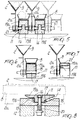
- the multiple-channel vibrating table comprises a table, generally designated by the reference numeral 1, which is constituted by a plurality of feeder troughs 2 which are arranged mutually side by side and extend parallel to one another.
- each feeder trough 2 has a V-shaped transverse cross-section which is fixed to the upper side of a vertical plate 2a.
- the feeder troughs 2 can be connected, by virtue of controllably activatable connection means 3, to motor means 4 which vibrate the troughs 2 so as to cause the advancement of the loose parts along the troughs 2 from an input station 5, constituted for example by a hopper 6, to an output station 7 which can be constituted by the inlet of a packaging machine or of a production line in general, as will be described in greater detail hereinafter.
- a return trough 8 arranged so as to receive the excess parts which exit from the feeder trough 2 and is connected to motor means activating said return trough 8 with a vibrating motion which makes the parts advance in a direction opposite to the advancement direction imparted to the parts in the feeder trough 2.
- each feeder trough 2 there is a return trough 8 for each feeder trough 2, and the feeder troughs 2 are provided with a lateral recess portion 9 on the side of the related return trough 8.
- the size of said recess portion 9 is a function of the feeding requirements and of the dimensions of the loose parts, so as to unload the excess parts fed in the troughs 2 onto the return troughs 8.
- leveling means for example a rod 10, which facilitate the passage of the excess parts from the feeder trough 2 to the return trough 8.
- the vibrating table is constituted by feeder troughs 2 alternated with return troughs 8.
- the motor means 4 impart to the feeder troughs 2 and to the return troughs 8 a vibration with reciprocating motion along a direction which has a component which is parallel to the longitudinal extension of the troughs, which are mounted respectively on first and second guiding means which define, for the troughs, sliding directions which are inclined with respect to the vibration direction imparted by the motor means so as to obtain the required effect of part advancement.
- Said first and second guiding means are constituted by blocks 11 which are applied to the fixed supporting structure 12 of the vibrating table.
- Each block 11 has, on its lateral faces, which are arranged vertically, two grooves 13 and 14 which are inclined in opposite directions with respect to the vibration direction 15 imparted to the troughs 2 and 8.
- the first groove 13 slidably accommodates a pin 16 which is fixed to the vertical plate 2a of the feeder trough
- the second groove 14 slidably accommodates a pin 17 fixed to the return trough 8 by means of a bracket-like element 18.
- each block 11 is made of two portions 19a and 19b which transversely delimit the two grooves 13 and 14 and are moved close together by the action of a spring 20 which acts on the lower face of the block.
- the spring 20 thus keeps the transverse walls of the grooves 13 and 14 in contact with the related pins 16 and 17, recovering any play which might arise due to wear.
- the groove 13 accommodates two pins 16 of two adjacent feeder troughs 2, and the space for the sliding of the two pins 16 is delimited by an intermediate partition 21.
- the vibrating table is preferably constituted by a plurality of pairs of troughs arranged mutually side by side, wherein each pair is constituted by a feeder trough 2 and by a return trough 8 which are mounted on two blocks 11 which are mutually spaced along the longitudinal extension of said troughs.
- the blocks 11 are arranged between these trough pairs so as to simultaneously support the feeder troughs 2 of two pairs of adjacent troughs.
- Each return trough 8 has a part discharge passage 22 which is arranged above a recovery channel 43 by means of which the parts arriving from the return trough 8 are collected and/or conveyed back to the hopper 6.
- the motor means 4 comprise a mass 23 which is vibrated with a reciprocating motion along the direction 15 by virtue of known means, such as for example a mechanical system with an eccentric element, not illustrated for the sake of simplicity.
- the direction 15, which is parallel to the longitudinal extension of the troughs 2 and 8, is preferably horizontal.
- the vibrating mass 23 is suspended, by means of flexible arms 24, from the fixed supporting structure 12 of the vibrating table, and a longitudinal end of the return troughs 8 is fixed to said vibrating mass.
- the feeder troughs 2 can be controllably connected to the vibrating mass 23, preferably in an individual manner, by virtue of the connection means 3 which comprise, for each trough 2, a flexible tab 25 which is fixed to a longitudinal end of the trough 2 and ends with a shaped sliding block 26 which can be coupled to a seat 27 which is shaped complementarily and is defined in the vibrating mass 23.
- Actuation means act on each tab 25 and can be controllably activated so as to engage or disengage the sliding block 26 with or from the seat 27 in order to connect or disconnect the related trough 2 to or from the vibrating mass 23.
- Said actuation means comprise a fluid-activated cylinder 28 which is supported by the fixed supporting structure 12 and acts with its stem 28a on a presser element 29 with the interposition of an articulation 30 of a known type which does not transmit transverse loads to the stem 28a.
- the presser element 29 is constituted by a cylindrical body 31 which passes through another cylindrical body 32 which has a larger diameter and is made of low-friction material for the tab 25 which it faces with its lower end.
- the lower end of the cylindrical body 31 passes through a longitudinal slot 33 of the tab 25 and ends with an enlarged head 34 which is accommodated in a seat 35 defined in the sliding block 26.
- the cylinder 32 can slide vertically in a seat 36 defined in the supporting structure 12 and has an upper shoulder 37 for the cylindrical body 32.
- the cylindrical body 31 has a shoulder 38 which is directed downward and faces an abutment of the cylindrical body 32.
- the cylinder 28 is actuated in the opposite direction, so that the sliding block disengages from the seat 27 and the tab 25 is pressed, by virtue of the action of the cylindrical body 31, against the lower end of the cylindrical body 32, thus locking the related feeder trough 2.
- the feeder troughs 2 can be actuated independently of one another according to the feeding requirements of the machine or production line arranged downstream of the vibrating table 1.
- the excess parts in fact fall into the return troughs 8 without causing alterations with respect to the required amount or arrangement. Furthermore, the parts discharged onto the troughs 8 are collected and can be easily fed back into the hopper 6.
- the materials employed, as well as the dimensions, may be any according to the requirements and the state of the art.
Landscapes
- Engineering & Computer Science (AREA)
- Mechanical Engineering (AREA)
- Jigging Conveyors (AREA)
- Feeding Of Articles To Conveyors (AREA)
Applications Claiming Priority (2)
| Application Number | Priority Date | Filing Date | Title |
|---|---|---|---|
| ITMI912883 | 1991-10-30 | ||
| ITMI912883A IT1251527B (it) | 1991-10-30 | 1991-10-30 | Piano vibrante multicanale per l'alimentazione di pezzi sfusi in genere |
Publications (2)
| Publication Number | Publication Date |
|---|---|
| EP0539882A2 true EP0539882A2 (de) | 1993-05-05 |
| EP0539882A3 EP0539882A3 (en) | 1993-11-18 |
Family
ID=11360987
Family Applications (1)
| Application Number | Title | Priority Date | Filing Date |
|---|---|---|---|
| EP19920118179 Withdrawn EP0539882A3 (en) | 1991-10-30 | 1992-10-23 | Multiple-channel vibrating table for feeding loose parts |
Country Status (3)
| Country | Link |
|---|---|
| US (1) | US5277300A (de) |
| EP (1) | EP0539882A3 (de) |
| IT (1) | IT1251527B (de) |
Families Citing this family (14)
| Publication number | Priority date | Publication date | Assignee | Title |
|---|---|---|---|---|
| US5445261A (en) * | 1992-02-03 | 1995-08-29 | Ishida Co., Ltd. | Mechanism for attaching trough to vibrating feeder |
| US5489019A (en) * | 1994-08-04 | 1996-02-06 | Stokes-Merrill Corporation | Feed tray for singularizing objects |
| US5704466A (en) * | 1996-02-23 | 1998-01-06 | Upper Limits Engineering Co. | Feed tray attachment for vibratory feeder |
| JPH09283986A (ja) * | 1996-04-18 | 1997-10-31 | Matsushita Electric Ind Co Ltd | 部品供給方法及びその装置 |
| US6109475A (en) * | 1998-04-14 | 2000-08-29 | Graham; S. Neal | Parts feeder system adaptable to both manual feed and auxiliary hopper feed |
| US6216850B1 (en) * | 1999-05-26 | 2001-04-17 | Paul A. Svejkovsky | Cyclically powered conveyor with flow leveler |
| US6347698B1 (en) * | 2000-07-05 | 2002-02-19 | Lipe Automation Corp. | Modular conveyor apparatus |
| US6814211B2 (en) * | 2001-07-12 | 2004-11-09 | Satake Usa, Inc. | Slide for sorting machine |
| JP4425000B2 (ja) * | 2004-01-06 | 2010-03-03 | 株式会社ブリヂストン | ゴム部材搬送装置、及びそれを有するゴム部材供給システム |
| EP1976364B1 (de) * | 2007-03-30 | 2011-09-07 | Mydata Automation AB | Mechanische Schnittstelle |
| US7743927B2 (en) * | 2008-02-13 | 2010-06-29 | Satake Usa, Inc. | Adjustable slide width reducer for gravity slide sorter |
| USD664576S1 (en) * | 2011-08-02 | 2012-07-31 | Sartorius Weighing Technology Gmbh | Vibrating table |
| CA2793336C (en) | 2012-10-26 | 2020-08-04 | Countlab Inc. | Retaining device for a vibration tray |
| DK3114053T3 (da) * | 2014-03-05 | 2021-12-13 | Buehler Ag | Maskine til separation af elementer |
Family Cites Families (10)
| Publication number | Priority date | Publication date | Assignee | Title |
|---|---|---|---|---|
| US3224553A (en) * | 1963-02-27 | 1965-12-21 | Milford A Campbell | Vibratory work feeding and orienting unit |
| US4037710A (en) * | 1974-07-11 | 1977-07-26 | Lipe-Rollway Corporation | Accumulator for object feeder |
| US4146123A (en) * | 1977-07-28 | 1979-03-27 | Champion International Corporation | Stick aligning and conveying method and apparatus |
| DE2740577A1 (de) * | 1977-09-09 | 1979-03-22 | Loewe Opta Gmbh | Teilefoerderer zum foerdern, speichern und zur automatischen entnahme von kleinen massenteilen |
| ATA27179A (de) * | 1978-01-25 | 1981-05-15 | Licentia Gmbh | Grossflaechiges schwingnutzgeraet |
| JPS5612220A (en) * | 1979-07-11 | 1981-02-06 | Matsushita Electric Ind Co Ltd | Parts feeding equipment |
| US4446959A (en) * | 1981-10-13 | 1984-05-08 | North American Philips Corporation | Multiple rail linear feed system |
| JPS58125512A (ja) * | 1981-12-14 | 1983-07-26 | Shinko Electric Co Ltd | 振動部品供給機 |
| WO1988007015A1 (en) * | 1987-03-20 | 1988-09-22 | Atlas Copco Aktiebolag | Vibratory feeding and orienting apparatus |
| IT1233486B (it) * | 1989-06-20 | 1992-04-02 | Gd Spa | Metodo e dispositivo per l'avanzamento, in successione, di prodotti appiattiti |
-
1991
- 1991-10-30 IT ITMI912883A patent/IT1251527B/it active IP Right Grant
-
1992
- 1992-10-23 US US07/965,327 patent/US5277300A/en not_active Expired - Fee Related
- 1992-10-23 EP EP19920118179 patent/EP0539882A3/en not_active Withdrawn
Also Published As
| Publication number | Publication date |
|---|---|
| US5277300A (en) | 1994-01-11 |
| EP0539882A3 (en) | 1993-11-18 |
| ITMI912883A0 (it) | 1991-10-30 |
| IT1251527B (it) | 1995-05-16 |
| ITMI912883A1 (it) | 1993-04-30 |
Similar Documents
| Publication | Publication Date | Title |
|---|---|---|
| US5277300A (en) | Multiple-channel vibrating table for feeding loose parts | |
| CN103180229B (zh) | 用于容器流的多功能调节单元 | |
| KR100799690B1 (ko) | 기계장치용 블랭크 홀더 및 기계장치용 블랭크 홀더를 작동시키기 위한 방법 | |
| KR880002732A (ko) | 분배공급 방법과 장치 | |
| US3547254A (en) | Mechanical full accumulating conveyor | |
| CN103920828A (zh) | 一种灯头自动分料装置 | |
| US3410607A (en) | Apparatus for feeding rod-like articles | |
| KR20180100487A (ko) | 중계 장치 | |
| US2966739A (en) | Apparatus for inserting bushings | |
| US5190139A (en) | Multiple-channel vibrating feeding table | |
| US2788882A (en) | Article feeding mechanism | |
| US4163487A (en) | Contact pin feeding and orienting apparatus | |
| JPS59182110A (ja) | 部品供給装置 | |
| CN109809122B (zh) | 一种玻璃自动上料机构 | |
| CN217798774U (zh) | 自动铆钉机 | |
| CN212333751U (zh) | 一种胶堵机用便于多通道上料的防水栓上料机构 | |
| US508092A (en) | Cracker-stacking machine | |
| JP2006063510A (ja) | 編機 | |
| CN104590860B (zh) | 一种大肉片定量投放设备 | |
| RU1815154C (ru) | Устройство дл групповой обработки деталей | |
| US3237749A (en) | Conveyor for incremental counter and loading means therefor | |
| CN109760113B (zh) | 一种尼龙棒料的切割设备 | |
| CN108814121B (zh) | 袋装弹簧制作设备及方法 | |
| GB1120173A (en) | Apparatus for feeding sweets or articles for wrapping | |
| CN210456439U (zh) | 一种柔性排钎机构 |
Legal Events
| Date | Code | Title | Description |
|---|---|---|---|
| PUAI | Public reference made under article 153(3) epc to a published international application that has entered the european phase |
Free format text: ORIGINAL CODE: 0009012 |
|
| AK | Designated contracting states |
Kind code of ref document: A2 Designated state(s): AT BE CH DE DK ES FR GB GR IT LI NL PT SE |
|
| PUAL | Search report despatched |
Free format text: ORIGINAL CODE: 0009013 |
|
| AK | Designated contracting states |
Kind code of ref document: A3 Designated state(s): AT BE CH DE DK ES FR GB GR IT LI NL PT SE |
|
| 17P | Request for examination filed |
Effective date: 19940428 |
|
| 17Q | First examination report despatched |
Effective date: 19950530 |
|
| STAA | Information on the status of an ep patent application or granted ep patent |
Free format text: STATUS: THE APPLICATION IS DEEMED TO BE WITHDRAWN |
|
| 18D | Application deemed to be withdrawn |
Effective date: 19951011 |