EP0540042B1 - Fibre optique acceptant une puissance élevée et sa méthode de fabrication - Google Patents
Fibre optique acceptant une puissance élevée et sa méthode de fabrication Download PDFInfo
- Publication number
- EP0540042B1 EP0540042B1 EP92118644A EP92118644A EP0540042B1 EP 0540042 B1 EP0540042 B1 EP 0540042B1 EP 92118644 A EP92118644 A EP 92118644A EP 92118644 A EP92118644 A EP 92118644A EP 0540042 B1 EP0540042 B1 EP 0540042B1
- Authority
- EP
- European Patent Office
- Prior art keywords
- optical fiber
- core
- doped
- cladding
- dopant
- Prior art date
- Legal status (The legal status is an assumption and is not a legal conclusion. Google has not performed a legal analysis and makes no representation as to the accuracy of the status listed.)
- Expired - Lifetime
Links
Images



Classifications
-
- G—PHYSICS
- G02—OPTICS
- G02B—OPTICAL ELEMENTS, SYSTEMS OR APPARATUS
- G02B6/00—Light guides; Structural details of arrangements comprising light guides and other optical elements, e.g. couplings
- G02B6/02—Optical fibres with cladding with or without a coating
- G02B6/036—Optical fibres with cladding with or without a coating core or cladding comprising multiple layers
- G02B6/03616—Optical fibres characterised both by the number of different refractive index layers around the central core segment, i.e. around the innermost high index core layer, and their relative refractive index difference
- G02B6/03622—Optical fibres characterised both by the number of different refractive index layers around the central core segment, i.e. around the innermost high index core layer, and their relative refractive index difference having 2 layers only
- G02B6/03633—Optical fibres characterised both by the number of different refractive index layers around the central core segment, i.e. around the innermost high index core layer, and their relative refractive index difference having 2 layers only arranged - -
-
- C—CHEMISTRY; METALLURGY
- C03—GLASS; MINERAL OR SLAG WOOL
- C03B—MANUFACTURE, SHAPING, OR SUPPLEMENTARY PROCESSES
- C03B37/00—Manufacture or treatment of flakes, fibres, or filaments from softened glass, minerals, or slags
- C03B37/01—Manufacture of glass fibres or filaments
- C03B37/012—Manufacture of preforms for drawing fibres or filaments
- C03B37/014—Manufacture of preforms for drawing fibres or filaments made entirely or partially by chemical means, e.g. vapour phase deposition of bulk porous glass either by outside vapour deposition [OVD], or by outside vapour phase oxidation [OVPO] or by vapour axial deposition [VAD]
- C03B37/01446—Thermal after-treatment of preforms, e.g. dehydrating, consolidating, sintering
-
- G—PHYSICS
- G02—OPTICS
- G02B—OPTICAL ELEMENTS, SYSTEMS OR APPARATUS
- G02B6/00—Light guides; Structural details of arrangements comprising light guides and other optical elements, e.g. couplings
- G02B6/02—Optical fibres with cladding with or without a coating
-
- G—PHYSICS
- G02—OPTICS
- G02B—OPTICAL ELEMENTS, SYSTEMS OR APPARATUS
- G02B6/00—Light guides; Structural details of arrangements comprising light guides and other optical elements, e.g. couplings
- G02B6/02—Optical fibres with cladding with or without a coating
- G02B6/02052—Optical fibres with cladding with or without a coating comprising optical elements other than gratings, e.g. filters
-
- C—CHEMISTRY; METALLURGY
- C03—GLASS; MINERAL OR SLAG WOOL
- C03B—MANUFACTURE, SHAPING, OR SUPPLEMENTARY PROCESSES
- C03B2201/00—Type of glass produced
- C03B2201/06—Doped silica-based glasses
- C03B2201/08—Doped silica-based glasses doped with boron or fluorine or other refractive index decreasing dopant
- C03B2201/12—Doped silica-based glasses doped with boron or fluorine or other refractive index decreasing dopant doped with fluorine
-
- C—CHEMISTRY; METALLURGY
- C03—GLASS; MINERAL OR SLAG WOOL
- C03B—MANUFACTURE, SHAPING, OR SUPPLEMENTARY PROCESSES
- C03B2203/00—Fibre product details, e.g. structure, shape
- C03B2203/10—Internal structure or shape details
- C03B2203/18—Axial perturbations, e.g. in refractive index or composition
-
- C—CHEMISTRY; METALLURGY
- C03—GLASS; MINERAL OR SLAG WOOL
- C03B—MANUFACTURE, SHAPING, OR SUPPLEMENTARY PROCESSES
- C03B2203/00—Fibre product details, e.g. structure, shape
- C03B2203/10—Internal structure or shape details
- C03B2203/22—Radial profile of refractive index, composition or softening point
-
- C—CHEMISTRY; METALLURGY
- C03—GLASS; MINERAL OR SLAG WOOL
- C03B—MANUFACTURE, SHAPING, OR SUPPLEMENTARY PROCESSES
- C03B2203/00—Fibre product details, e.g. structure, shape
- C03B2203/36—Dispersion modified fibres, e.g. wavelength or polarisation shifted, flattened or compensating fibres (DSF, DFF, DCF)
-
- G—PHYSICS
- G02—OPTICS
- G02B—OPTICAL ELEMENTS, SYSTEMS OR APPARATUS
- G02B6/00—Light guides; Structural details of arrangements comprising light guides and other optical elements, e.g. couplings
- G02B6/02—Optical fibres with cladding with or without a coating
- G02B6/02214—Optical fibres with cladding with or without a coating tailored to obtain the desired dispersion, e.g. dispersion shifted, dispersion flattened
- G02B6/02219—Characterised by the wavelength dispersion properties in the silica low loss window around 1550 nm, i.e. S, C, L and U bands from 1460-1675 nm
- G02B6/02276—Dispersion shifted fibres, i.e. zero dispersion at 1550 nm
Definitions
- This invention relates to a high-power acceptable optical fiber and a method for fabricating the optical fiber.
- the amount of light which can be launched into an optical fiber is limited.
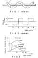
- a method for causing strain in an optical fiber is reported as a conventional technique for suppressing stimulated Brillouin scattering. This method utilizes the fact that application of strain to the optical fiber changes the Brillouin frequency shift.
- optical fibers are helically stranded in a cable so as to change the strain caused in the axial direction of the fibers.
- the above-reported optical fiber cable employs optical fibers 11 of a double helix structure, extending in the axial direction, and the strain applied to the fibers 11 alternately changes from compressive strain to tensile strain, and vice versa.
- the Brillouin frequency shift varies in different portions of the fibers, increasing the gain bandwidth of the Brillouin scattering spectrum. Consequently, the threshold value for the amount of light increases, over which the stimulated Brillouin scattering will occur.
- Fig. 2 shows an axial profile of tension on a Brillouin scattering-suppressed optical fiber consisting of a SiO 2 core and an F-doped SiO 2 cladding.
- an optical fiber fabricated by the conventional methods for applying axial-directional strain to an optical fiber is liable to break. If the strain applied to a usual optical fiber increases from 0.1% to 0.2%, the factor of breakage per 1 km will become 10 7 times higher. This is indicated in Yutaka Mitsunaga, Yutaka Katsuyama, Takakazu Kobayashi, Yukinori Ishida, "Method for Securing the Rigidity of Optical Fiber by Screening Test" (Transactions of the Institute of Electronics and Communication Engineers of Japan, Vol. J66-B, No. 7, 1983). To avoid such breakage, a technique for increasing the rigidity of an optical fiber by coating the fiber with a carbon film, must be employed in the conventional methods. In addition, since the optical fiber is kept in a particular strained state in the conventional method shown in Fig. 1, the cable structure is inevitably limited. It is therefore very difficult to employ the structure in the actual optical fiber line.
- a high-power acceptable optical fiber comprising a core and a cladding provided on the outer peripheral surface of the core, and forming the optical fiber together with the core.
- document EP-A-0 175 067 describes a method of fabricating the high-power acceptable optical fiber, the method comprising the steps of forming a preform of the optical fiber and drawing the optical fiber from the preform.
- the preform-forming step includes the step of forming a silica glass soot by a vapor-phase axial deposition method and the step of consolidating the silica glass soot into a transparent glass in a furnace.
- an inert gasis is used as an atmospheric gas during the process of sintering the soot preform produced by the vapour phase axial deposition method.
- the invention has been made in consideration of the above circumstances, and the object of the present invention is to provide a high-power acceptable optical fiber for long-distance transmission which can reliably operate for a long period of time, and a method of fabricating the optical fiber.
- the present invention differs from document EP-A-0 175 067 in the steps performed after the vapour phase axial deposition method.
- the fact that the stimulated Brillouin frequency shift depends on the dopant concentration in the fiber preform is utilized.
- the threshold value at which the stimulated Brillouin scattering will occur can be increased by changing the dopant concentration in the axial direction of the fiber, in a state in which the relative refractive index profile, which is normalized by the maximum refractive index of the core, is kept same in any cross section of the fiber perpendicular to the axial direction thereof.
- the amount of light which can be launched to the fiber can be increased, and hence the transmission distance can be considerably increased.
- the fiber can be used in a reliable manner for a long period of time.
- Fig. 3 shows axial variations in the refractive indices of the core and cladding of an optical fiber according to a first embodiment.
- the index profile has a stepwise shape, and GeO 2 is used as a dopant in both the core and cladding.
- reference sign Le denotes an effective length along which stimulated Brillouin scattering will occur.
- the aforementioned Cotter's paper describes that the effective length is approximately 4.3/ ⁇ ( ⁇ : loss (dB/km)) where the length of the optical fiber is sufficiently long.
- the optical loss of the optical fiber is 0.21 dB/km, the effective length Le is 20.5 km.
- the threshold value of the Brillouin scattering can be increased by varying the dopant concentration in the fiber over the entire effective length Le.
- FIG. 4 shows a refractive index profile in a cross section at a given length z of the fiber.
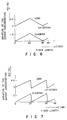
- Fig. 6 shows a dopant-concentration profile for realizing the above-described fiber structure, which are taken in the axial direction of the optical fiber.
- 1 mol%-GeO 2 doping increases the refractive index of GeO 2 -doped SiO 2 relative to undoped SiO 2 by about 0.1%.
- the amount of the dopant is continuously varied such that the refractive index difference ⁇ between the core and cladding at a given length z is kept at 0.3%.
- the optical fiber in the embodiment is designed such that the threshold value of the intensity of input light is ten times higher than that in a usual optical fiber. Specifically, it is reported in the paper written by N. Shibata, Y. Azuma, T. Horiguchi, and M. Tateda, "Brillouin-Gain Spectra for Single-Mode Fibers Having Various Core/Cladding Material Compositions" (ECOC '88), that the frequency shift of stimulated Brillouin scattering light varies in proportional to the amount of a dopant in the core. Further, Cotter describes that the gain bandwidth of the stimulated Brillouin scattering spectrum of silica is approx. 16 MHz for a 1.55 ⁇ m-wavelength light.
- the stimulated Brillouin frequency shift must be varied by 160 (16 ⁇ 10) MHz.
- N. Shibata et al. describe that the frequency shift due to GeO 2 is 107 MHz/mol%.
- the intensity of light is attenuated to a value equal to the input-light threshold value of the conventional fiber, so that there is no possibility of occurrence of the stimulated Brillouin scattering.
- an optical fiber with a dopant profile as shown in Fig. 7 can provide the same effect as that of the fiber with the dopant profile shown in Fig. 6.
- the amount of a dopant is varied in the axial direction of the fiber such that the Brillouin frequency shift is G-times (ten times in the above-described embodiment) or more larger than the gain bandwidth (16 MHz) of the Brillouin scattering spectrum of a usual optical fiber, the effect that the threshold value of the amount of input light becomes G-times higher can be obtained even though the index profile in a cross section has a shape other than a stepwise shape.
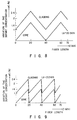
- FIG. 8 and 9 show axial variations in the dopant concentrations in the optical fiber of the second embodiment.
- a waveguide structure can be formed by doping the cladding with F of an amount larger than that of F in the core.
- the diameters of the core and cladding are set to 10 ⁇ m and 125 ⁇ m, respectively, and the relative refractive index difference ⁇ is set to 0.3%.
- the refractive index of the light-output end of the optical fiber is made equal to that of the conventional optical fiber, there will not occur such an adverse effect as reflection of light at the junction between the fibers.
- the optical fiber of the invention since the optical fiber of the invention has no strain, it can provide a more reliable long-distance light transmission line than the conventional strain-applied optical fiber.
- Combinations of dopants employed in the high-power acceptable optical fiber of the invention are specifically as follows, including those employed in the first and second embodiments:
- GeO 2 and F are used as dopants
- the same effect as in the embodiments can be obtained even when Al 2 O 3 , P 2 O 5 , etc., are used as dopants.
- the same effect also can be obtained when the structure of the invention is applied to optical fibers of particular structures such as a dispersion-shifted optical fiber and a polarization-maintaining optical fiber.
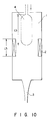
- a soot fabricated by a VAD method and consisting of a GeO 2 -doped silica core and silica cladding was heated and consolidated into a transparent glass. This consolidation was performed in a zone furnace in the atmosphere of F. The soot was gradually moved downward at a constant speed in the zone furnace for consolidation shown in Fig. 10, into which SF 6 and He gases were supplied. When the soot reached a heater unit 2 in the furnace, the concentration of F doped in the soot was fixed, thereby consolidating the preform into a transparent glass. The concentration of F can be varied in the longitudinal direction of the preform thereof by temporally varying the amount of the supplied gases in the atmosphere.
- Fig. 11 shows an example of a refractive index profile in the longitudinal direction of the preform of the high-power acceptable optical fiber of the invention.
- the length of a sample of optical fiber is about 29 km.
- the amount of F doped in the fiber is varied in the longitudinal direction by a value corresponding to a relative refractive index difference of about 0.2%, while the relative refractive index difference between the core and cladding of any portion of the fiber in the longitudinal direction is kept constant.
- the refractive index of the glass relative to SiO 2 decreases by 0.4% in units of 1 wt% of F.
- the amount of doped F varies by about 0.5 wt% between the light-input end of the fiber (i.e., start portion in Fig. 11) and the light-output end (i.e., end portion).
- the optical loss of the optical fiber in the example is 0.43 dB/km and 0.23 dB/km at 1.3 ⁇ m and 1.55 ⁇ m, respectively, and is substantially equal to that of a usual optical fiber.
- the Brillouin frequency shift changes by 356 MHz in units of 1 wt% of F for a 1.55 ⁇ m-wavelength light. This means that it will change by 424 MHz for a 1.3 ⁇ m-wavelength light.
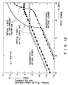
- Fig. 12 shows measurement results indicating the relationship between the input power of light with a wavelength of 1.3 ⁇ m, the transmitted-light power, and the scattered-light power.
- the threshold value of the input power in the optical fiber of the invention is about 13 dBm, whereas the threshold value of the input power in the conventional optical fiber is about 7 dBm. That is, the fiber of the invention is enhanced by about 6 dB, as compared with the conventional one.
- the threshold value of the amount of input light can be enhanced by varying the amount of F doped in the optical fiber in the longitudinal direction thereof.
- Fig. 13 shows an embodiment, in which the invention is applied to a dispersion-shifted optical fiber with a three-layered structure.
- a silica glass soot for forming a GeO 2 -doped central core 5 and a GeO 2 -doped side core 6, and a silica glass soot for forming undoped cladding 7 are formed by the VAD method. Thereafter, these soots are consolidated into glass in the furnace 1 shown in Fig. 10, while the concentration of F in the atmosphere is being varied.
- the refractive index profile of the optical fiber of the invention is not limited to the stepwise shape, but may have any desired shape.
Landscapes
- Physics & Mathematics (AREA)
- General Physics & Mathematics (AREA)
- Optics & Photonics (AREA)
- Chemical & Material Sciences (AREA)
- Engineering & Computer Science (AREA)
- General Chemical & Material Sciences (AREA)
- Chemical Kinetics & Catalysis (AREA)
- Life Sciences & Earth Sciences (AREA)
- Thermal Sciences (AREA)
- General Life Sciences & Earth Sciences (AREA)
- Geochemistry & Mineralogy (AREA)
- Manufacturing & Machinery (AREA)
- Materials Engineering (AREA)
- Organic Chemistry (AREA)
- Glass Compositions (AREA)
Claims (7)
- Fibre optique acceptant une puissance élevée comprenant:une âme; etune gaine sur la surface périphérique externe de l'âme, et formant la fibre optique (11) avec cette âme, caractérisée en ce que les concentrations d'un agent/des agents, dopant, respectivement, l'âme et la gaine, changent dans la direction de l'axe de la fibre optique, l'âme ayant le même profil d'indice de réfraction relatif dans toute coupe transversale de celle-ci prise dans une direction perpendiculaire à la direction de son axe, le profil d'indice de réfraction relatif étant normalisé par un indice de réfraction maximal de l'âme.
- Fibre optique acceptant une puissance élevée selon la revendication 1, caractérisée en ce que l'agent de dopage est au moins l'un parmi un groupe consistant en GeO2, P2O5, Al2O3, et F.
- Fibre optique acceptant une puissance élevée selon la revendication 1, caractérisée en ce que l'âme et la gaine sont réalisées en silice dopée au F, et la quantité d'agent dopant l'âme est différente de celle dopant la gaine, la différence entre les deux étant constante.
- Fibre optique acceptant une puissance élevée selon la revendication 1, caractérisée en ce que l'âme et la gaine sont réalisées en silice dopée au GeO2, et la concentration en agent dopant change dans la direction de l'axe de la fibre optique (11).
- Fibre optique acceptant une puissance élevée selon la revendication 1. caractérisée en ce que l'âme et la gaine sont réalisées en dopant des particules vitreuses de silice dopée au GeO2 avec F comme agent de dopage dont la quantité est variable longitudinalement.
- Fibre optique acceptant une puissance élevée selon la revendication 1, caractérisée en ce que l'âme et la gaine sont réalisées, respectivement, en silice dopée au GeO2 et en silice pure, et sont dopées avec F comme agent dont la quantité est variable longitudinalement.
- Méthode de fabrication d'une fibre optique acceptant une puissance élevée, comprenant:l'étape de formation d'une préforme d'une fibre optique (11); etl'étape consistant à étirer la fibre optique à partir de la préforme;ladite étape de formation d'une préforme incluant l'étape de formation de particules vitreuses de silice (4), par une méthode de dépôt axial en phase vapeur, et l'étape de consolidation des particules vitreuses de silice en verre transparent dans un four (1),caractérisée en ce que l'étape de consolidation inclut l'étape de chauffage des particules vitreuses de silice dans le four alors que la concentration de l'atmosphère en F est temporairement changée, de façon à changer la quantité de F dopant les particules longitudinalement.
Applications Claiming Priority (4)
| Application Number | Priority Date | Filing Date | Title |
|---|---|---|---|
| JP28764391 | 1991-11-01 | ||
| JP287643/91 | 1991-11-01 | ||
| JP256975/92 | 1992-09-25 | ||
| JP4256975A JP2753426B2 (ja) | 1991-11-01 | 1992-09-25 | 高入力光ファイバ及びその母材の製造方法 |
Publications (2)
| Publication Number | Publication Date |
|---|---|
| EP0540042A1 EP0540042A1 (fr) | 1993-05-05 |
| EP0540042B1 true EP0540042B1 (fr) | 1997-01-02 |
Family
ID=26542995
Family Applications (1)
| Application Number | Title | Priority Date | Filing Date |
|---|---|---|---|
| EP92118644A Expired - Lifetime EP0540042B1 (fr) | 1991-11-01 | 1992-10-30 | Fibre optique acceptant une puissance élevée et sa méthode de fabrication |
Country Status (3)
| Country | Link |
|---|---|
| US (1) | US5303318A (fr) |
| EP (1) | EP0540042B1 (fr) |
| DE (1) | DE69216366T2 (fr) |
Cited By (1)
| Publication number | Priority date | Publication date | Assignee | Title |
|---|---|---|---|---|
| CN102351414A (zh) * | 2011-07-05 | 2012-02-15 | 华南师范大学 | 一种制备稀土掺杂微结构光纤的方法 |
Families Citing this family (18)
| Publication number | Priority date | Publication date | Assignee | Title |
|---|---|---|---|---|
| US5504829A (en) * | 1993-12-27 | 1996-04-02 | Corning Incorporated | Optical fiber for soliton transmission and method of making |
| DE4420287A1 (de) * | 1994-06-10 | 1995-12-14 | Sel Alcatel Ag | Lichtwellenleiter für faseroptische Verstärker für den Wellenlängenbereich um 1550 nm |
| US5509101A (en) * | 1994-07-11 | 1996-04-16 | Corning Incorporated | Radiation resistant optical waveguide fiber and method of making same |
| TW371650B (en) * | 1995-12-04 | 1999-10-11 | Sumitomo Electric Industries | Method for producing an optical fiber quartz glass preform |
| US5851259A (en) * | 1996-10-30 | 1998-12-22 | Lucent Technologies Inc. | Method for making Ge-Doped optical fibers having reduced brillouin scattering |
| AU745481B2 (en) * | 1997-07-15 | 2002-03-21 | Corning Incorporated | Suppression of stimulated brillouin scattering in optical fiber |
| JP3533950B2 (ja) * | 1998-08-07 | 2004-06-07 | トヨタ自動車株式会社 | 非線形光学シリカ薄膜の製造方法及び非線形光学シリカ素子 |
| FR2782807A1 (fr) * | 1998-08-27 | 2000-03-03 | Alsthom Cge Alcatel | Fibre optique a usage d'amplificateur optique avec une gaine dopee au fluor |
| DE19961514A1 (de) * | 1999-12-20 | 2001-06-21 | Siemens Ag | Anordnung zur Reduzierung der Stimulierten Brillouin-Streuung in einer Lichtwellenleiterfaser |
| TWI233430B (en) * | 2000-01-28 | 2005-06-01 | Shinetsu Chemical Co | Method for manufacturing glass base material, glass base material, and optical fiber |
| US6898351B2 (en) * | 2000-11-07 | 2005-05-24 | Photon-X, Llc | Optical fiber transmission systems with suppressed light scattering |
| KR100438348B1 (ko) * | 2001-12-28 | 2004-07-02 | 주식회사 머큐리 | 길이 방향으로 굴절율이 상이한 광섬유 및 이에 적합한광섬유 제조 방법 |
| EP1764633A1 (fr) * | 2005-09-09 | 2007-03-21 | Draka Comteq B.V. | Fibre optique ayant une diffusion de Brillouin stimulée réduite |
| US8965162B2 (en) * | 2006-09-27 | 2015-02-24 | Peter Dragic | Anti-guiding waveguides |
| US7577178B2 (en) * | 2007-01-23 | 2009-08-18 | Peter Dragic | Narrow linewidth injection seeded Q-switched fiber ring laser based on a low-SBS fiber |
| US9321222B2 (en) * | 2013-08-13 | 2016-04-26 | Baker Hughes Incorporated | Optical fiber sensing with enhanced backscattering |
| JP6826089B2 (ja) * | 2018-10-30 | 2021-02-03 | ファナック株式会社 | ファイバレーザ用光ファイバ、ファイバレーザ及びファイバレーザ用光ファイバの製造方法 |
| CN115084987B (zh) * | 2022-06-28 | 2025-08-19 | 武汉睿芯特种光纤有限责任公司 | 泵浦吸收与纤芯数值孔径沿轴向呈负相关单调渐变的光纤及其制备方法 |
Family Cites Families (11)
| Publication number | Priority date | Publication date | Assignee | Title |
|---|---|---|---|---|
| US4053204A (en) * | 1976-07-30 | 1977-10-11 | Bell Telephone Laboratories, Incorporated | Optical fiber having reduced dispersion |
| US4053205A (en) * | 1976-07-30 | 1977-10-11 | Bell Telephone Laboratories, Incorporated | Optical fiber having reduced dispersion |
| JPS569236A (en) * | 1979-06-29 | 1981-01-30 | Fujitsu Ltd | Manufacture of optical fiber |
| US4344670A (en) * | 1980-05-01 | 1982-08-17 | Corning Glass Works | Optical waveguide soot preform with reduced inner layer stress and method of making |
| JPS57115042A (en) * | 1981-01-08 | 1982-07-17 | Nippon Telegr & Teleph Corp <Ntt> | High power optical transmission system |
| FI74371C (fi) * | 1982-06-04 | 1988-01-11 | British Telecomm | Optisk oeverfoering. |
| JPS6172644A (ja) * | 1984-09-19 | 1986-04-14 | Sumitomo Electric Ind Ltd | 低損失光フアイバの製造方法 |
| US4691990A (en) * | 1984-11-13 | 1987-09-08 | American Telephone And Telegraph Company, At&T Bell Laboratories | Optical fiber with depressed index outer cladding |
| CA1290942C (fr) * | 1985-03-18 | 1991-10-22 | Michihisa Kyoto | Methode de fabrication d'elements preformes, en verre, pour la production de fibres optiques |
| JPH0684254B2 (ja) * | 1988-06-29 | 1994-10-26 | 三菱電線工業株式会社 | 耐放射線性マルチプルファイバ |
| CA2053212A1 (fr) * | 1991-10-11 | 1993-04-11 | Cheng-Kuei Jen | Fibres optiques a seuils de retrodiffusion de brillouin stimulee pre-etablis |
-
1992
- 1992-10-27 US US07/967,816 patent/US5303318A/en not_active Expired - Fee Related
- 1992-10-30 DE DE69216366T patent/DE69216366T2/de not_active Expired - Fee Related
- 1992-10-30 EP EP92118644A patent/EP0540042B1/fr not_active Expired - Lifetime
Cited By (2)
| Publication number | Priority date | Publication date | Assignee | Title |
|---|---|---|---|---|
| CN102351414A (zh) * | 2011-07-05 | 2012-02-15 | 华南师范大学 | 一种制备稀土掺杂微结构光纤的方法 |
| CN102351414B (zh) * | 2011-07-05 | 2015-07-15 | 华南师范大学 | 一种制备稀土掺杂微结构光纤的方法 |
Also Published As
| Publication number | Publication date |
|---|---|
| EP0540042A1 (fr) | 1993-05-05 |
| DE69216366D1 (de) | 1997-02-13 |
| US5303318A (en) | 1994-04-12 |
| DE69216366T2 (de) | 1997-07-17 |
Similar Documents
| Publication | Publication Date | Title |
|---|---|---|
| EP0540042B1 (fr) | Fibre optique acceptant une puissance élevée et sa méthode de fabrication | |
| JP5425391B2 (ja) | 光ファイバ | |
| US6449415B1 (en) | Optical fiber and method of manufacturing the same | |
| US4447127A (en) | Low loss single mode fiber | |
| US5732178A (en) | Single-mode optical fiber | |
| US7742671B2 (en) | Optical fiber | |
| WO1999004298A1 (fr) | Suppression de la diffusion de brillouin stimulee dans une fibre optique | |
| US20040218882A1 (en) | Large effective area high SBS threshold optical fiber | |
| US6943935B2 (en) | Dispersion-managed cable for raman-assisted transmission | |
| Kanamori | Transmission loss of optical fibers; achievements in half a century | |
| CA2565879C (fr) | Grande longueur d'onde, fibre de mode simple a noyau de silice pure et procede de fabrication de celle-ci | |
| JPH10501633A (ja) | 光ウェーブガイド | |
| RU2271025C2 (ru) | Одномодовое оптическое волокно и способ изготовления одномодового оптического волокна | |
| JP2005520200A (ja) | 分散補償光ファイバおよびこれを用いた光伝送線 | |
| WO2005054916A2 (fr) | Fibre optique nzds a seuil sbs eleve | |
| JP3386948B2 (ja) | 光ファイバ | |
| US7536074B2 (en) | Optical fiber | |
| JP2753426B2 (ja) | 高入力光ファイバ及びその母材の製造方法 | |
| JPH10339819A (ja) | 光増幅用光ファイバ | |
| JP2002082250A (ja) | 低非線形単一モード光ファイバ | |
| JP4434172B2 (ja) | 分散補償光ファイバ | |
| JPH1130725A (ja) | 低分散光ファイバ | |
| JPS62116902A (ja) | 広帯域低分散光フアイバ | |
| JP3307518B2 (ja) | 低分散光ファイバの製法 | |
| KR20010060739A (ko) | 분산제어광섬유 및 그의 제조 방법 |
Legal Events
| Date | Code | Title | Description |
|---|---|---|---|
| PUAI | Public reference made under article 153(3) epc to a published international application that has entered the european phase |
Free format text: ORIGINAL CODE: 0009012 |
|
| 17P | Request for examination filed |
Effective date: 19921030 |
|
| AK | Designated contracting states |
Kind code of ref document: A1 Designated state(s): DE FR |
|
| 17Q | First examination report despatched |
Effective date: 19950821 |
|
| GRAG | Despatch of communication of intention to grant |
Free format text: ORIGINAL CODE: EPIDOS AGRA |
|
| GRAH | Despatch of communication of intention to grant a patent |
Free format text: ORIGINAL CODE: EPIDOS IGRA |
|
| RAP1 | Party data changed (applicant data changed or rights of an application transferred) |
Owner name: NIPPON TELEGRAPH AND TELEPHONE CORPORATION |
|
| GRAH | Despatch of communication of intention to grant a patent |
Free format text: ORIGINAL CODE: EPIDOS IGRA |
|
| GRAA | (expected) grant |
Free format text: ORIGINAL CODE: 0009210 |
|
| AK | Designated contracting states |
Kind code of ref document: B1 Designated state(s): DE FR |
|
| REF | Corresponds to: |
Ref document number: 69216366 Country of ref document: DE Date of ref document: 19970213 |
|
| ET | Fr: translation filed | ||
| PLBE | No opposition filed within time limit |
Free format text: ORIGINAL CODE: 0009261 |
|
| STAA | Information on the status of an ep patent application or granted ep patent |
Free format text: STATUS: NO OPPOSITION FILED WITHIN TIME LIMIT |
|
| 26N | No opposition filed | ||
| PGFP | Annual fee paid to national office [announced via postgrant information from national office to epo] |
Ref country code: FR Payment date: 20020912 Year of fee payment: 11 |
|
| PGFP | Annual fee paid to national office [announced via postgrant information from national office to epo] |
Ref country code: DE Payment date: 20021220 Year of fee payment: 11 |
|
| PG25 | Lapsed in a contracting state [announced via postgrant information from national office to epo] |
Ref country code: DE Free format text: LAPSE BECAUSE OF NON-PAYMENT OF DUE FEES Effective date: 20040501 |
|
| PG25 | Lapsed in a contracting state [announced via postgrant information from national office to epo] |
Ref country code: FR Free format text: LAPSE BECAUSE OF NON-PAYMENT OF DUE FEES Effective date: 20040630 |
|
| REG | Reference to a national code |
Ref country code: FR Ref legal event code: ST |